fuel pressure CHEVROLET CAVALIER 1984 1.G Owners Manual
[x] Cancel search | Manufacturer: CHEVROLET, Model Year: 1984, Model line: CAVALIER, Model: CHEVROLET CAVALIER 1984 1.GPages: 105, PDF Size: 24.23 MB
Page 6 of 105
Downloaded from www.Manualslib.com manuals search engine SECTION 1
BEFORE DRIVING YOUR CAVALIER
TRANSAXLE
While reading this manual, you will nole many references 10 Ihe "transaxle." The transaxle is a transmission and differential (axle) combined in a singl ,e unit.
To avoid confusion, the word
"transaxle" will be used throughout this manual 10 refer to bolh Ihe transmission and differenlial funclions.
DRIVER DAILY CHECKUST
Be sure you know how to use your vehicle and its equipment before operating it
Before Entering the Vehicle
1. See that windows, mirrors and lights are clean and unobstructed.
2. If any lire does not look normal, check it with a pressure gage.
3. Look for fluid leaks .
4. Be sure everything is properly stowed.
5. Check the area behind the vehicle if you are about to back up.
__ Before Driving Off
1. Lock all doors.
2. Adjust the seat and any movable head restraint
3. Adjust inside and outside mirrors.
4. DO NOT allow anyone to ride where there is no seat belt ; and ALWAYS properly fasten the seat belt.
5. Check that all the warning lights work as the key is turned to "Run" or "Start"
6. Check all gages (including the fuel gage).
7 . Release the parking brake (and make sure the
"BRAKE " light turns .off).
See related topics in this manual
or the Maintenance Schedule folder H problems are found.
STOWING THINGS IN (OR ON) THE VEHICLE
CAUTION: Put luggage or cargo In the trunk, or rea' area if postible. Cargo weight,
whether In the trunk or rear area, should be located as far forward as possible. Cargo weight on the roof Shoukt be positioned .s evenly as possible. Secure all i1ems in place to help keep them -from being thrown about and injuring people during a cot"-ion or sudden maneuver. Do not pile luggage or cargo higher than the seetbaCks. Do not place anything on the filler panel, or any cargo cover between the rear seat~.ck and window.
GUARD AGAINST THEFT
Your new Cava~er has many features to help prevent then of the vehicle, its
equipment, and contents. But these anti-then features
depend upon you to work.
t -1
Page 23 of 105
Downloaded from www.Manualslib.com manuals search engine Frequent short trips, excessive idling and use of the air conditioner in cool
weather (when "vent" would provide adequate comfort), all can contribute to
decreased fuel economy .
The careful attention you give your vehicle as far as maintenance and repairs
are concerned will also help fuel economy . Proper engine and air cleaner
maintenance, lubrication intervals, wheel alignment and tire inflation pressures, when closely adhered to, will pay dividends in improved fuel economy as well as longer vehicle Irte.
Fuel Selection
Use only unleaded gasoline meeting the octane ratings given under "Fuel Requirements " in this section of the manual. Unleaded gasoline must be used
for the
emission control system to operate properly . Leaded gasoline will
damage the Computer Command
Control system oxygen sensor (if so equipped) and affect emission control. Using leaded gasoline can also damage
other parts of the emission control system and could result in loss of emission warranty coverage.
STEERING COLUMN CONTROLS
ANTl-THEFT STEERING COLUMN LOCK
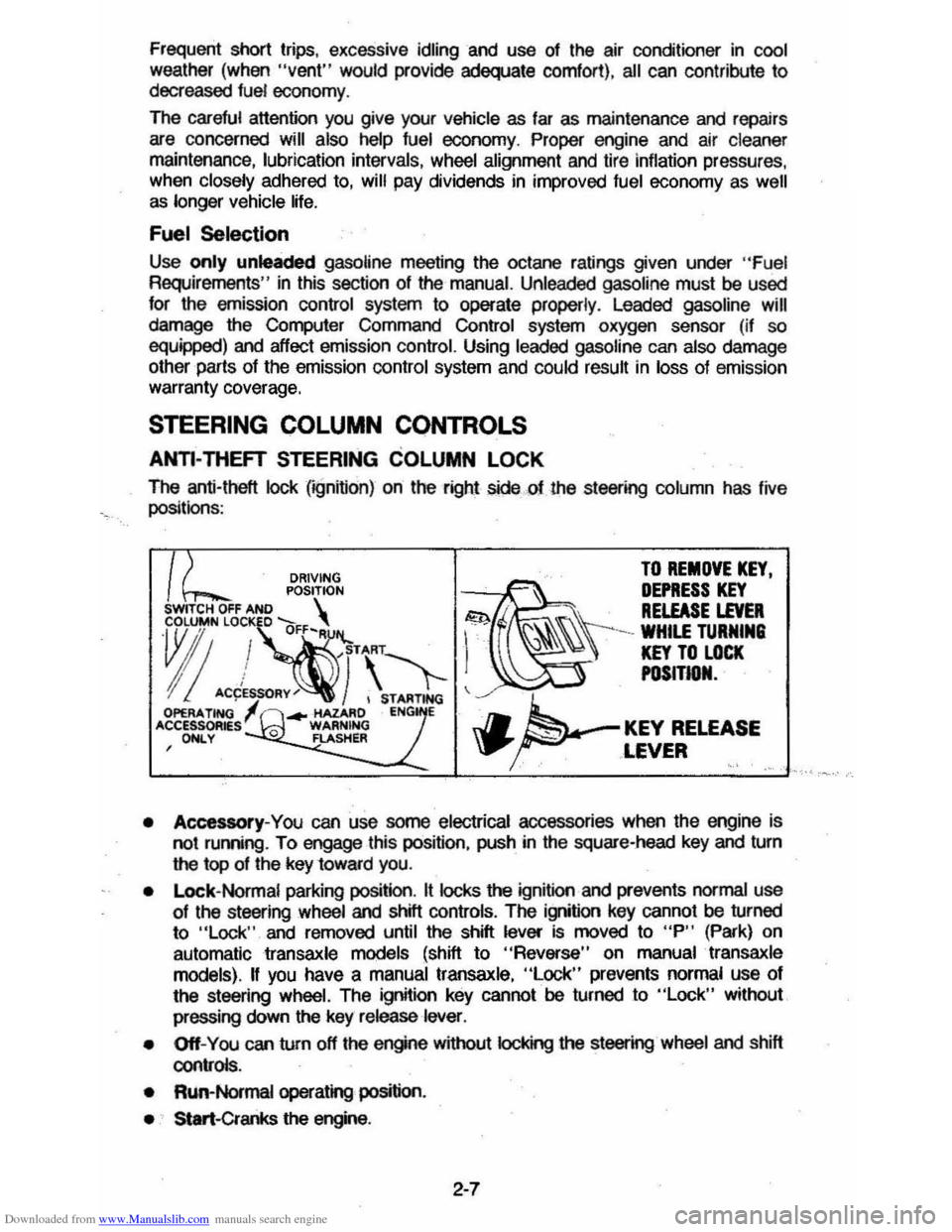
The anti-theft lock (;gnifion) on the right sidecf the st_ing column has live
positionS :
DRIVING TO REMOVE KEY.
POSITION ~~ DEPRESS KEY SWITCH OFF AND S . . RELEASE LEVER
~"!~·\'1-1 ~\\\-=~"
I! ACCES~RY~) , STARTING ~ OPERA. TING ... -HAZARD ENG E 'CCESSOR~sl 0 WARNING J.. KEY RELEASE , ONLY FLASHER \P' ... ~ ,LEVER '.' .'
• Accessory-You can use some electrical accessories when the engine is
not ruming . To engage this position, push in the square-head key and turn
the top of the key 10ward you.
•
Lock- Normal parking position. It locks the ignition and prevents normal use 01 the st_ing wheel and shill controls. The ignition key cannot be turned
to "Lock " and removed until the shift lever is moved to "P" (Park) on
automatic
transaxle models (shift to "Reverse" on manual transaxle
models).
II you have a manual transaxle, "Lock" prevents normal use 01
the steering wheel. The ignition key cannot be turned to "Lock" without
pressing down
the key release lever.
• Off-You can turn off the engine without IocI
• Run-Normal operating position.
• Start-Cranks the engine .
2-7
Page 28 of 105
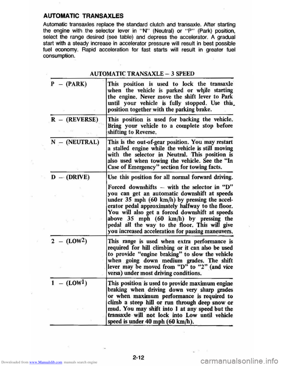
Downloaded from www.Manualslib.com manuals search engine AUTOMATIC TRANSAXLES
Automatic Iransaxles replace the standard clutch and Iransaxle . After starting
the engine with the selector lever in "N" (Neutral) or "P" (Park) posnion,
select the range desired (see table) and depress the accelerator. A gradual start with a steady increase in ac ce lerator pressure will result in best possible
fuel economy. Rapid acceleration for fast starts will result in greater fuel consumption.
P -(PARK)
AUTOMATIC TRANSAXLE - 3 SPEED
This position is used to lock the transaxle
when the vehicle
is parked or wlVle starting
the engine. Never move the shift
lever to Park
until your vehicle is fully stopped . Use this.
position together with the parking brake.
R - (REVERSE) This position
is used fot backing the vehicle.
" Bring your vehicle to a complete stop before
shifting to Reverse .
N - (NEUTRAL)
This is the out-of.gear position. You may restart
a stalled engine while the vehicle
is still moving
with the selector
"in Neutral. This position is also used when towing the vehicle. See the "In Case of Emergency" section for towing facts.
D
- " (DRIVE) Use this position for all normal forward driving.
Forced downshifts -with the selector in "D"
you can get an automatic downshift at speeds
under
3S mph (60 km/h) by pressing Ihe accel· erator pedal approximately halfway to the 1I00r.
You
will also get a forced downshift at speeds
above 35 mph
(60 km/h) by pressing the
pedal all the way to the 1I00r . This will give
you increased acceleration for passing maneuvers.
2 - (LOW2) This range is used when extra performance is
required for hill climbing or it can also be used to provide "engine braking" to slow the vehicle
when going down medium grades. The shift lever may'be moved from "D" to "2n(and vice
versa) under most driving conditions.
1 - (LOWl) This position
is used to provide maximum engine
braking
when driving down very sharp grades
or when maximum performance is required
to
climb a steep hill or run through deep snow or
mud. You may shift into 1 at any speed but the
transaxle " will not lock into Low until vehicle
speed
is under 40 mphl.60 km/h).
2-12
Page 37 of 105
Downloaded from www.Manualslib.com manuals search engine • Amount of fuel required for fill-up may not exactly correspond to gage.
• Needle may not move away from FULL until some time after fill-up.
• Needle may move during turns; stops and accelerations.
When the ignition switch is turned to the OFF position, the needle will not
necessarily return
all the way to the EMPTY mark.
Oil Pressure Light
When the ignition is turned to "Run," the "Oil" warning light appears until the
engine is started. Thereafter, the light should be off unless there is insufficient
oil pressure or engine idle speed is below normal. If the light should come on
at any time while driving (other than momentarily at idle speed or after a
sudden stop), stop immediately and investigate the cause of
low oil pressure.
This could possibly be caused by low oil level in the crankcase. Engine
operation with low oil pressure will 9ause damage to the engine.
Engine Coolant Temperature Light
This light is located in the instrument cluster and is designed to come on to warn the driver that the engine coolant has overheated and immediate
action is required to correct the condition. As a check that the bulb and its
circuit are working, the light will come on during engine starting; if it does not,
have it repaired
promptly. If the light comes on at any other time, see "Engine
Cooling System Overheating" in "In Case of Emergency," Section 3 of this manual.
CAUTION: It the Engine Coolant Temperature Light shows an overheat condition or you have other reason to suspect the engine may be overheating, continued operation of the engine EVEN FOR A SHORT TIME may result in a fire and the risk of personal injury and/or severe vehicle damage. Take immediate action as outlined under "Engine Cooling System Overheating" in "In Case of Emergency," Section 3.
Generator Indicator Light
The VOLT light is designed to come on when the ignition key is in the "RUN" position, but before the engine is started. After the engine starts, the light
should go out and remain out. If the light remains· on when engine is running,
have your authorized
dealer locate and correct the trouble as soon as possible.
Shift Indicator Light
The Shift Indicator Light is covered in the "Manual Transaxle" information in
this section.
"Check Engine" Light
Most gasoline engine vehicles sold in the Unijed States (and some vehicles
sold
in Canada) have the Computer Command Control system.
Vehicles with the Computer Command Control system include a "CHECK
ENGINE" light
on the instrument panel designed to indicate the need for
system service. It will come on during engine starting to let you know the bulb
is working. (The light will stay on a short time after the engine starts.)
2-21
Page 38 of 105
Downloaded from www.Manualslib.com manuals search engine Have the system repaired n the "CHECK ENGINE" light does not come on during engine starting. If the light comes on, either intermittently or
continuously while driving, service to the Computer Command Control system
is required. AHhough in most cases the vehicle is drivable, and does not
require towing, see your authorized
dealer as soon as possible for service of
the system.
Continued driving without having the Computer
Command Control system serviced could cause damage to the emission control system. It could also affect fuel economy and drivability.
See also "Computer Command Control system" in Section 5 of this manual.
Brake System Warning Light
The regular braking system is a dual system designed so that one part will
provide some braking if there is a
loss of hydraulic pressure in the other part of
the system. The system has a
"BRAKE" warning light located in the
instrument panel. The "BRAKE" light is designed to come on briefly during
engine starting so you can check that the bulb is okay. To serve as a reminder,
the
light should stay on when the parking brake is not fully released and the
ignition is
on. Have the system repaired if the light does not come on when it should. This warning light does not do away with the need for brake inspection
and maintenaflce. The brakelluid level must be checked regularly. See your
Maintenance Schedule folder for other brake checks.
I! the light remains on aller engine start up or comes on during operation of the vehicle, it may mean that there is something wrong with part of the brake
system.
What
to do:
1. Check to see that the parking brake has been released. I! it has been:
2. Pull off the road and stop carefully. Remember that:
• Stopping distances may be longer.
•
You may have to push harder on the pedal.
•
The pedal may go down farther than normal.
3. Tryout the brakes by starting and stopping on the road shoulder--then:
• I! you judge it to be safe, drive cautiously at a safe speed to the
nearest dealer for repair. Or,
• Have vehicle towed to the nearest dealer for repair.
Continued driving without getting necessary repairs
could be dangerous.
Tachometer
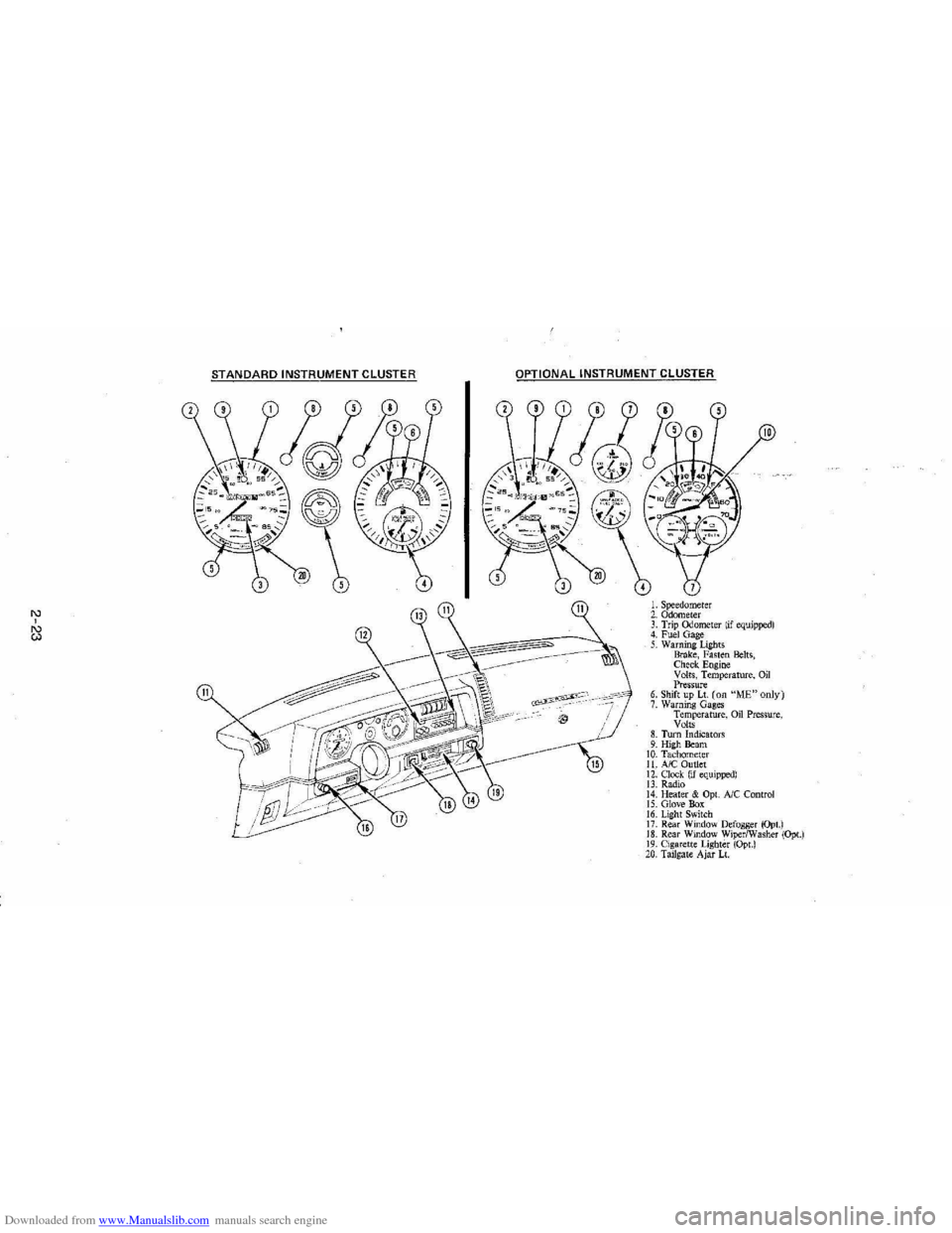
The optional tachometer indicates the speed of the engine in revolutions per
minute. The indicated number, times
100, gives the engine speed. Operating
the engine with the tachometer reading in the color-coded high-speed area
could lead to serious engine damage.
Voltmeter
When the engine is operating, the voltmeter indicates the electrical system
voltage. During minimum electrical load, the pointer will read to the right of the
center.
As the electrical load is increased, or in stop-and-go driving, the pointer
will rotate to the Ieli. A meter reading continuously in the left or right zone
indicates
an electrical system failure. Cause of the failure should be determined and corrected.
2-22
Page 39 of 105
Downloaded from www.Manualslib.com manuals search engine '" ,
t:l
STANDARD INSTRUMENT CLUSTER
IJ
12
OPTIONAL INSTRUMENT CLUSTER
~~~~-:'----,~~:
l'l
1l
10
L Speedometer 2. Odometer 3. Trip ()jometer lif equipped) 4. Fuel Gage 5. Warning Lights Brake, Fasten Belts, Check. Engine Volts, Temperature, Oil Pressure 6. Shift up Lt. (on "ME"only) 7. Warning Gages Temperature, on Pressure, Volts 8. Turn Indicators 9. High Beam 10. Tachomet er 11. A/C Outlet 12. Clock. (if equipped) 13. Radio 14. Heater & Opt. Ale Control 15. Glove Box 16. Lig ht Switch 17. Rear Window Defogger (Opt.) 18. Rear Window WiperlWasher (Opt.) 19. Cigare tt e Lighter (Opt.) 20, Tailgat e Ajar Lt.
Page 65 of 105
Downloaded from www.Manualslib.com manuals search engine 3. Install wheel and tire assembly and install hub cap by pushing or hitting
into place (the wheel can be mounted with hub cap in place). The hub cap
must be oriented by engaging the bump on the side of the hub cap
retention tab with the cutout on the side of the wheel pilot hole.
Compact Spare
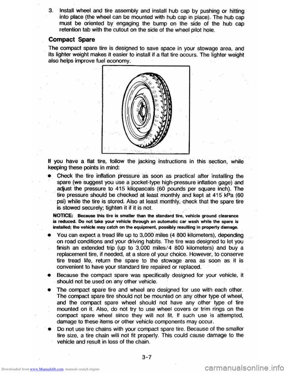
The compact spare tire is designed to save space in your stowage area, and
its lighter weight makes it easier to install if a flat tire occurs. The lighter weight also helps improve fuel economy. ~--~------~~
" you have a flat tire, follow the jacking Instructions in this section, while keepingihese points in mind:
• Check the tire inflaiionpressureas soon as practical after installing the
spare (we suggest you use a 'pocket-type high'pressure inflation gage) and
adjust the pressure to 415
kilopascals (60 pounds per square inch). The
tire pressure should be checked at least monthly and kept at 415 kPa (60
psi) while the tire is stored . Also at least monthly , ·qheck that the spare lire is stowed securely ; tighten it if ~ is not.
NOTICE: Bee ... this tire is smaller than the standard tire, vehicle ground clearance is reduced. Do not take your vehicle through an automatic car wash while ~ spare I. Installed; the vehicle may catch on the equipment, possibly resulting In property damag_.
• YOU can expect a tread life up to 3,000 miles (4 800 kilometers), dependiQg on road conditions and your driving habits. The tire was designed to let you
finish an extended trip (up to 3,000 miles/4 800 kilometers) and buy a replacement tire, -if needed, at a store of your choice. However, to conserve
tire tread ~fe, return the spare to the stowage area as' soon as it is
convenient to have your standard tire repaired or replaced.
• Because the compact spare was specnically designed for your vehicle , ~ should not be used on any other vehicle.
• The compact spare tire and wheel are designed for use with each other.
The compact spare tire should not be mounted on any other type of wheel, and the compact spare wheel should not have any other type of tire
mounted on it. Also, do not try to use wheel covers or trim rings on the
CQr1l>aCt spare whe el since they will not fit. If such use is attempted,
damage to tIlese items or other vehicle components may occur.
• Do not use tire chains with your :compact spare tire. Because of the smaller tire size, a tire chain will not fit properly. This could cause damage to the
vehicle and result in loss of the chain.
3-7
Page 74 of 105
Downloaded from www.Manualslib.com manuals search engine SECTION 5
SERVICE AND MAINTENANCE
Your authorized dealer has factory trained technicians and Genuine GM Parts
to service your vehicle properly_ For expert advice and quality service, see your authorized dealer.
CAUTION: As with any machine, take care when making any check, doing any maintenance, or making any repair, to avoid being injured. Some of the MATERIALS in this vehicle may also be hazardous if used, serviced, or handled improperly. Improper or incomplete service can affect the vehicle itself which may in turn result in personal
injury, or damage to the vehicle or its equipment. H you have ANY question about carrying out some service, have the work done by a skilled technician.
REPLACEMENT FASTENERS
During vehicle maintenance, any fasteners used to replace older ones must
have the same measurements and strength as those removed, whether metric or customary. (The numbers on the heads of rnetric bons and on the surfaces
of metric nuts show their strength. Customary bolts use radial lines to show
this,
while most customary nuts do not have strength markings.) Fasteners
taken from the vehicle should be saved for re-use in the same spot when
possible. Where a fastener cannot be used again, take care to choose a
replacement that matches the old one. For information and help, see your
authorized dealer.
CAUTION: This vehicle is primarily dimensioned In the metric system. Most fasteners
are metric and many are very close in dimension to well· known customary fasteners in the inch system. Mismatched or incorrect fasteners can result in damage to the vehicle or possibly personal injury.
MAINTENANCE SCHEDULE
For owner convenience, a separate folder ,has. bee" providef;1 with your vehicle which outlines the maintenance your vehicle requires. The Maintenance
Schedule folder is supplemented by this section of the Owner's Manual.
Read this publication for a full understanding of your vehicle's maintenance
needs.
If you need a replacement Maintenance Schedule, see your dealer or contact the . Consumer . Aelations Representative, . Chevrolet Central Office,
Chevrolet Motor Division, Warren, MichigarL4809ll-13t~2-550Q1 (In Canada, contact the Customer Services Representative, General MotorsoT---
Canada LId., Oshawa, Ontario, L1J 5Z6; 416/644-6624).
FUEL CAP
The fuel cap is located behind a hinged door on the right'rear fender. For your
convenience there
is a fuel cap hanger located on the filler door.
The
fuel tank filler cap has a "s£rew-on ratcheting type" feature.
• To remove -rotate cap counterclockwise to clear the inside of the filler
neck. This will allow any residual pressure to escape.
• To install - reverse this procedure and tighten cap securely until a
"ratcheting",
clicking sound is heard indicating cap is on properly.
5-1
Page 86 of 105
Downloaded from www.Manualslib.com manuals search engine /" VEHICLE CAPACITY OCCUP."TS COLD TIRE PRESSURE ' , ~~, mT CtR RR TOTAL C_, ~E~R
MAX [ LOAD I [ 1
A A TIRE [ I
.. T"ES AAf ,.qT ,~o ... OONiNG '00' "50 ". 'P" TO THE'" SIZE R'V,""ME>.<:lEl) PR"5lJRES
SPARE TIRE ,
SIZE ( )
MAXIMUM LUGGAGE/CARGO LOAD CAPACITY
Coupe and Sedan Station Wagon 60.0 kg/' 321bs. 40.0 kg/88Ibs.
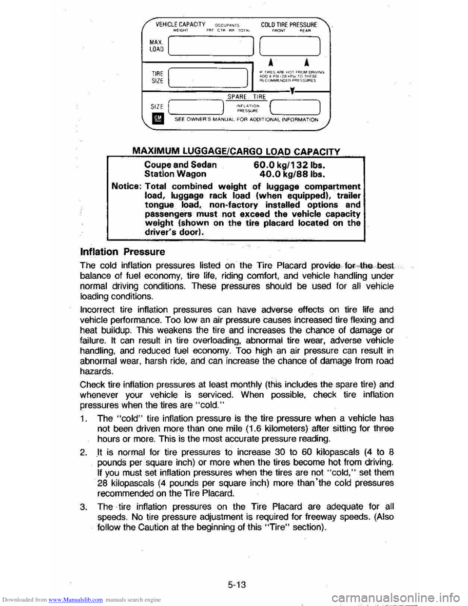
Notice: Total combined weight of luggage compartment load, luggage rack load (when equipped), trailer tongue load, non-factory installed options and
passenge'rs' must. not exceed the vehicle capacity weight (shown on the tire placard located on the driver's door).
Inflation Pressure
The cold inflation pressures listed on the Tire Placard provide forAIlebest
balance of fuel economy, tire life, riding comfort, and vehicle handling under normal driving conditions. These pressures should be used for all vehicle
loading conditions.
Incorrect tire inflation pressures can have adverse effects on tire life
and vehicle performance. Too Iowan air pressure causes increased tire flexing and
heat buildup. This weakens the tire and increases the chance of damage or
failure. It can result in tire overloading, abnormal tire wear, adverse vehicle handling, and reduced fuel economy. Too high an air pressure can result in
abnormal wear, harsh ride, and can increase the chance of damage from road
hazards.
Check tire inflation pressures at
least monthly (this includes the spare tire) and
whenever your vehicle is serviced. When possible, check tire inflation
pressures
when the tires are "cold."
1. The "cold" tire inflation pressure is the tire pressure when a vehicle has
not been driven more than one mile (1.6 kilometers) after sitting for three
hours or
more. This is the most accurate pressure reading.
2. .It is normal for tire pressures to increase 30 to 60 kilopascals (4 to 8 pounds per square inch) or more when the tires become hot from driving.
If you must set inflation pressures when the tires are not "cold," set them
28 kilopascals (4 pounds per square inch) more than'the cold pressures
recommended on the Tire Placard.
3. The· tire inflation pressures on the Tire Placard are adequate for all speeds. No tire pressure adjustment is required for freeway speeds. (Also
follow
the Caution at the beginning of this "Tire" section).
5-13
Page 99 of 105
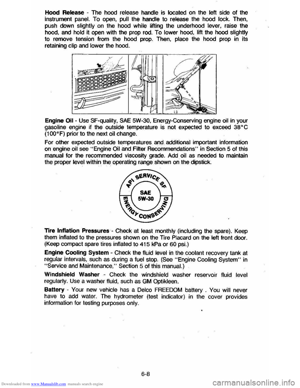
Downloaded from www.Manualslib.com manuals search engine Hood Release -The hood release handle is located on the left side of the
instrument panel. To open, pull the handle to release the hood lock. Then,
push down
slightly on the hood while lifting the underhood lever, raise the
hood, and hold it open with the prop rod. To lower hood, lift the hood slightly
to remove tension from the hood prop. Then, place the hood prop in its
retaining
clip and lower the hood.
Engine
Oil - Use SF-quality, SAE 5W-30, Energy-Conserving engine oil in your gasoline engine if the outside temperature is not expected to exceed 38" C
(100"F)
prior to the next oil change.
For other expected outside temperatures
and additional important information on engine oil see "Engine Oil and Filter Recommendations" in Section 5 of this
manual for the recommended viscosity grade. Add oil as needed to maintain
the proper level within the operating range shown on the dipstick.
Tire
Inflation Pressures -Check at least monthly (including the spare). Keep
them inflated to the pressures shown on the Tire Placard on the left front door. (Keep compact spare tires inflated to 415 kPa or 60 psi.)
Engine
Cooling System -Check the fluid level in the coolant recovery tank at
regular intervals, such as during a fuel stop. (See "Engine Cooling System" in "Service and Maintenance," Section 5 of this manual.)
Windshield Washer -Check the windshield washer reservoir fluid level
regularly. Use a washer fluid, such as GM Optikleen.
Battery -Your new vehicle has a Delco FREEDOM battery . You will never
have to add water. The hydrometer (test indicator) in the cover provides information for testing purposes only.
6-8