spare wheel CHEVROLET CAVALIER 1984 1.G Owners Manual
[x] Cancel search | Manufacturer: CHEVROLET, Model Year: 1984, Model line: CAVALIER, Model: CHEVROLET CAVALIER 1984 1.GPages: 105, PDF Size: 24.23 MB
Page 62 of 105
Downloaded from www.Manualslib.com manuals search engine coolant level in the see-through recovery tank. The coolant level should be at
or above the
"FULL HOT" mark on the recovery tank.
CAUTION: Keep hand., toots and clothing -away from the engine COOling fa", to help prevent personIl intUry. lhiIlan is electric and can come on whether Or not the engine Is rUnning. 111. tan can start automatically In .respon .. to a heat sensor when the ignition Is in "Run."
Make sure the water pu"",, belts are not broken, or off the pulleys , and that the fan runs when the engine is running and there is an indication on the instrument panel of an overheat condition.
If the coolant level in the recovery tank is low, look for leaks at the radiator
hoses and connections, heater hoses and connections, radiator I and water pump. If you find major leaks, or spot other problems that may have caused
the engine to overheat,
do not run the engine untilthese problems have been
corrected. If you do not find a leak or other problem, caretully add coolant to
the recovery tank. (Coolant is a mixture of ethylene glycol antifreeze and water; see "Engine Cooling System" in "'Service and Maintenance," Section 5, for the proper antifreeze and mixture.) .
CAUTION: Under: some:' conditione, the ethylen~ glycol In engine coolant Is . combustible. -To help avoid being burned, DO NOT spill antifreeze or coolant on the exhauat system or hot engine parts..
If the coolant level in the recovery tank is at the correct level but there is still
an indication on the instrument panel of an overheat condition:
•
You may add coolant directly to the radiator. YOU MUST LET ENGINE COOL FIRST. See "Coolant Replacement" under "Engine Cooling
System"
in Section 5, "Service and Maintenance" in this manual. Follow steps t through 3 for the correct way to remove the radiator
cap
and add coolant.
Once the Engine Coolant Temperature light has gone out (or the Engine Coolant Temperature gage no longer signals an overheat condition), you can
resume
driving at a reduced speed. Return to normal driving after about ten
minutes If the light does not come back on (or the gage pointer does not again
show
ao overheat condition).
tf no cause for the overheat condition was found, see a qualified service technician.
JACKING
CAUTION
To help avoid personal injury:
• FollOW all jacking and stowage instructions .
• Use jack only for lifting this vehicle during wheel change.
• Never get beneath the vehicle, start or run engine while vehicle is
supported by jack.
• Always securely restow spare tire (or flat tire) and all jacking equipment.
3-4
Page 63 of 105
Downloaded from www.Manualslib.com manuals search engine JACKING INSTRUCTIONS
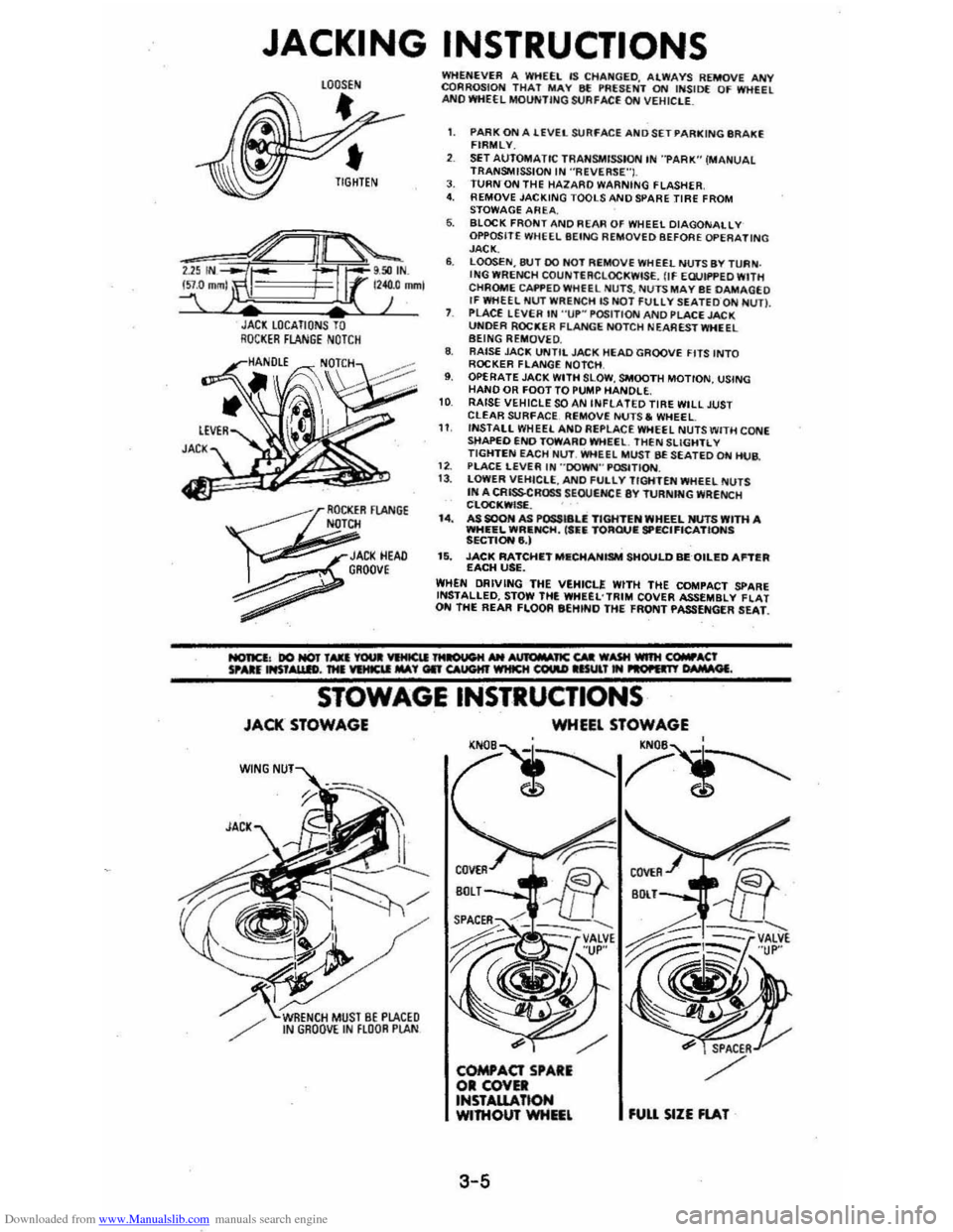
JACl LOCATIONS TO RQCI(ER FLANGE NOTCH
~
OCKER FlANGE N
JACI(HEAD , GROOve
~
WHENEVER A WHEEL IS CHA~GED. ALWAYS REMOVE ANY CQRROSIOH THAT MAY 8f !'RUENT ON INSID( OF WHEEL ANO WHEEL MOUNTING StJAFACE ON VEHIClE_
1. PARK ON A lEVEL SURFACE AND SET PARKING IIR AKE FIRMLY.
SET AUTOMATIC TRANSMISSION IN "PARK" (MANUAL TRANSMISSION IN ·'ReVERSE"I. J. TURN ON THE HAlARO WARNING FLASHER 4. REMOVE JACKING TOOLS AND SPARE TIRE FROM
STOWAGE AREA. 6. BLOCK FRONT AND REAR OF WHEEL DIAGONALLY OPPOSITE WHEEL BEING REMOVED BEFORE OPERATING JACK. 6. LOOSEN,8tH DO HOT REMOVE WHEEL NUTS BY TURN . ING WRENCH COUNTERCLOCKWISE. flf EWIf'PED WITH
CHROME CAI'f'EDWHfEL NU TS , NUTS MAY BE DAMAGEO If WHEEL NUT WRENCH lS NOT FUllY SEATEDQN NUn. PLACE LEVER IN "UP~ POSITION AND PLACE JACK UNOER ROCKER FLANGE NOTCH NEA REST WHEEL BEING REMOVE D. 8. RAISE JAC!!; UNTIL JACK HEAD GROOVE FITS INTO ROCKER FLANGE NOTCH , 9. OPERATE JACK WITH SLOW , SMOOTH MOTION, USING HAND OR FOOT TO PUMP HANDLE. 10 RAISE VEHICLE SOAN INfLATED TIRE WILL JUST CLEAR SURfACE. Ri;MOVE NUTS. WHEEL 11 INSTALL WHEEL ANO Ai;PLACE WHEEL NUTS WITH CONE sttAPEO END TOWARO WHEEl. THEN SLiGHTL V TIGHTEN EACH Nl.IT. WHEEL MUST BE SEATED ON HUB.
1 2. PlACE LEVER IN "'DOWN'" P~TION. 13 . lOWER VEHICLE, ANO fULlY TIGHTEN WHEEL NUTS IN A CRISSCROSS SEOUtNCE 8Y TURNfNG WRENCH CLOC!!;WISf. . I.. AS SOON AS POSSI8U TIGHTEN WHEEL NUTS WITH A WHEEL WRIlNCH, ('fiIi TORQUIE SPECIFICATIONS SECTIONe,) 15. JACK RATCHIETMIlCHANISM SHOULD BEQILED Antill EACH USE. WHEN DRIVING THE VEHICLE WITH THE COMPACT SPARE INSTALLED, STOW THE WHUL'TRIM COVER ASSEMBLY flAT ON THE REAR FLOOR eEHINO THE FRONT PASSENGER SEAT.
STOWAGE INSTRUCTIONS
JACK STOWAGE
W(NG
WHEEL STOWAGE
'N
3-5
fUU SIZE FlAT
Page 64 of 105
Downloaded from www.Manualslib.com manuals search engine Stowage of Tire and Jack
CAUTION: Always securely reatow the, spare tire assembly (or flat tir.), all jacking
equipment, and the cover , using the means provided . When driving the car with the Compact Spare instel~. stow the ",Met COYer in the trunk. In station wagons and hatchbecks, when the rear seat Is folded down, stow the wheel cover nat on the rear floor behind the right front seat. When the r •• r' seat is up, stow the wheel cover in the rear area . This will help keep SUch1tung. trom being thrown about and injuring people during II colhion or • sudden maneuver ..
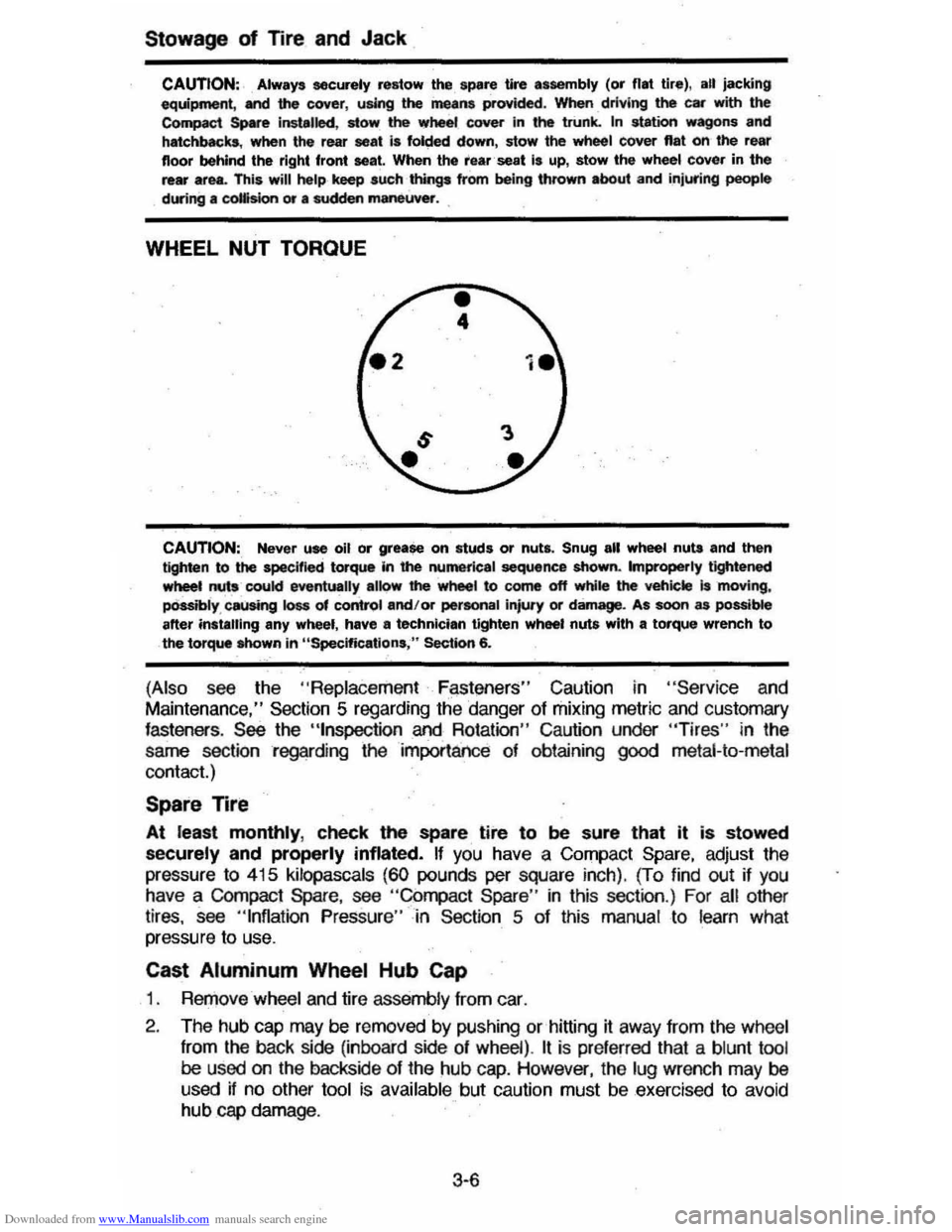
WHEEL NUT TORQUE
CAUTION:, Never use oil or grease on studs or nuts. Snug all wheel nuta and then tighten to the specified torque In the numerical sequence shown. Improperly tightened wheet nuts coukl eventually alk>w' the wheel to come off while the veh;ckt is 'moving, pOssibly , causing loss of control and/or pertonal injury or damage. As soon as possible after instilling any wheel, have II technician tighten wheel nuts with a torque wrench to the torque Mlown in "Specifications ," Section 6.
(Also see the "Replace ment F~st!3ners" Caution in "Servic e and
Maintenance," Section 5 regarding the danger of mixing metric and customary fasteners . See the "tnspection and Rotation" Caution under "Tires" in the
same section regarding the importance of obtaining
good metal-to-metal
contact.)
Spare Tire
At least monthly, check the spare tire to be sure that it is stowed
securely and properly inflated. If you have a Compact Spare, adjust the
pressure
to 415 kilopascals (60 pounds per square inch). (To find out if you have a COmpact Spare, see "Compact Spare " in this section .) For all other
tires, see "Inflation Pressure"-in Section 5 of this manual to learn what
pressure to use.
Cast Aluminum Wheel Hub Cap
1 . RerJ)ove wheel and tire assemb ly from car.
2 . The hub
cap may be removed by pushing or hitting it away from the wheel
from
the back side (inboard side of wheel) . It is pre ferred that a blunt tool be used on the backside of the hub cap. However, the lug wrench may be
used if no other tool is available but caution must be exercised to avoid hub cap damage .
3·6
Page 65 of 105
Downloaded from www.Manualslib.com manuals search engine 3. Install wheel and tire assembly and install hub cap by pushing or hitting
into place (the wheel can be mounted with hub cap in place). The hub cap
must be oriented by engaging the bump on the side of the hub cap
retention tab with the cutout on the side of the wheel pilot hole.
Compact Spare
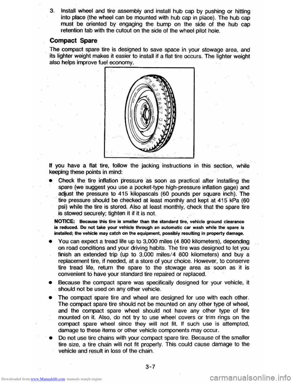
The compact spare tire is designed to save space in your stowage area, and
its lighter weight makes it easier to install if a flat tire occurs. The lighter weight also helps improve fuel economy. ~--~------~~
" you have a flat tire, follow the jacking Instructions in this section, while keepingihese points in mind:
• Check the tire inflaiionpressureas soon as practical after installing the
spare (we suggest you use a 'pocket-type high'pressure inflation gage) and
adjust the pressure to 415
kilopascals (60 pounds per square inch). The
tire pressure should be checked at least monthly and kept at 415 kPa (60
psi) while the tire is stored . Also at least monthly , ·qheck that the spare lire is stowed securely ; tighten it if ~ is not.
NOTICE: Bee ... this tire is smaller than the standard tire, vehicle ground clearance is reduced. Do not take your vehicle through an automatic car wash while ~ spare I. Installed; the vehicle may catch on the equipment, possibly resulting In property damag_.
• YOU can expect a tread life up to 3,000 miles (4 800 kilometers), dependiQg on road conditions and your driving habits. The tire was designed to let you
finish an extended trip (up to 3,000 miles/4 800 kilometers) and buy a replacement tire, -if needed, at a store of your choice. However, to conserve
tire tread ~fe, return the spare to the stowage area as' soon as it is
convenient to have your standard tire repaired or replaced.
• Because the compact spare was specnically designed for your vehicle , ~ should not be used on any other vehicle.
• The compact spare tire and wheel are designed for use with each other.
The compact spare tire should not be mounted on any other type of wheel, and the compact spare wheel should not have any other type of tire
mounted on it. Also, do not try to use wheel covers or trim rings on the
CQr1l>aCt spare whe el since they will not fit. If such use is attempted,
damage to tIlese items or other vehicle components may occur.
• Do not use tire chains with your :compact spare tire. Because of the smaller tire size, a tire chain will not fit properly. This could cause damage to the
vehicle and result in loss of the chain.
3-7
Page 87 of 105
Downloaded from www.Manualslib.com manuals search engine 4. Always use a tire pressure gage when checking inflation pressures (we
suggest you purchase a
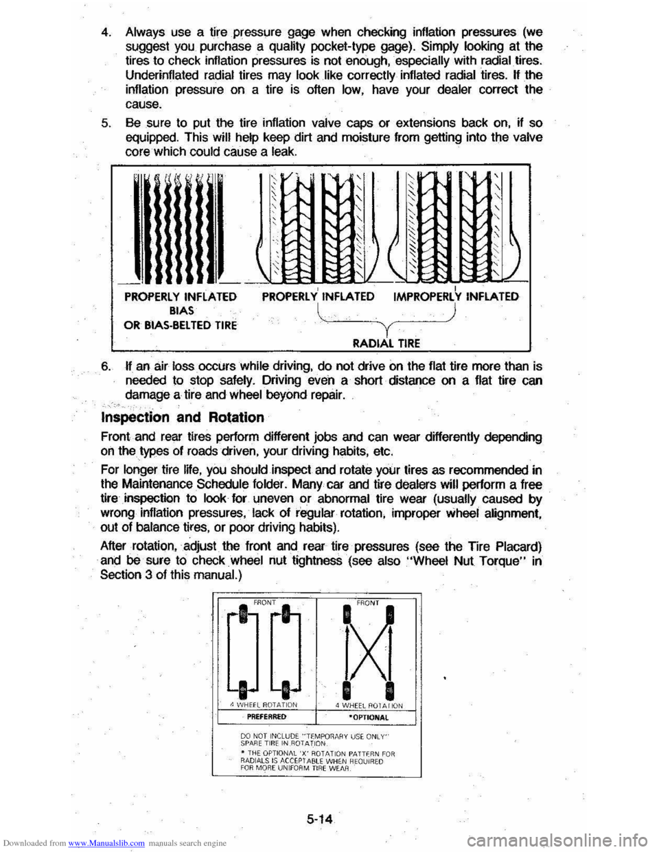
quality pocket-type gage). Simply looking at the tires to check inflation pressures is not enough, . especially with radial. tires.
Underinflated radial tires may look like correctly inflated radial tires. H the
inflation pressure on a tire is often low, have your dealer correct the
cause.
5. Sesure to put the tire inflation valve caps or extensions back on, if so
equipped. This will help keep dirt and moisture from getting into the valve core which could cause a leak.
't! [' V-. , ,-',/ ,
~v"
, " ,
, ,,-I"-v " I'V " ' v-I'-,
" "
,/ " I~ ~::;: ~ ~, ,/
~ J ( " ~ ~ ~ r;S ) :::: ~ ~ t;: ~/ 2~ t: ,
\' , --I PROPERLY INflATED PROPERLY INFLATED IMPROPERLY INFLATED BIAS l ) OR BIAS-BelTED TIRE Y RADIAL TIRE
6. H an air loss. occurs while driving, do not drive on the flat tire more than is
needed to stop safely. Driving even a short distance on a flat tire can
damage a tire and
wheel beyond repair.
Inspection and Rotation
Front and rear tires perform different jobs and can wear differently depending
on the types of roads driven, your driving habits, etc.
For
longer tire IHe, you shOuld inspect and rotate your tires as recommended in
the Maintenance Schedule folder. Many car and tire dealers will perform a free
tire
inspection to look for \meven or abnormal tire Wear (usually caused by
wrong inflation pressures, lack of regular rotation, improper wheel alignment,
out of bslance tires, or poor driving habits).
After rotation, adjust the front and rear tire pressures (see the Tire
Placard)
and be sure to check wheel nut tightness (see also "Wheel Nut Torque" in
Section 3 of this manual.)
fXi
I I 4 WHEEL ROT A I iON ·OPTIONAl
00 NOT INCLUDE "TfMPOT1MIY uS~ ONLY' SPARE TIR E IN .R01 AllON • THE OPTIONAL 'X' ROTATIO N PATTfR N FO R RADIALS IS ACCEPTABU WHE N HEQUIRW
FOR MO RE UNIfOR M TIRE WEAR
5-14
Page 102 of 105
Downloaded from www.Manualslib.com manuals search engine STereo.. 2-3 1 Tapu System ..... ....... .............. ........... 2-30 Rear WnJow Defogger ...•.•.......•.• .. . 2,26 Roar Window Washer/Wiper.. .. 2,29 Aegstration.. &5 Engine Number. &5 VehICle identifICation Number. &5 Replacement Fastener .. 5 -1
Restarting.
Restraints Child ... Lap Belts .. Methods Of Restr~ring Children •.. ReM Seat .. Reslraill lor Pfegnan WomtHI • . Shoulder Belts ___________ .......•..•.•.. Rool
2 -11
'-II ',9, 1-10 1-11 1·9 . HO H H l. l-10
Luggage
ca-rier .... ...... ............. 2-40, 2-4 Removable Panel. 2-37 Rotation. Tire .. Safoty BeltS (Seat Belts) .
5-14
,-, Carrior, InfiYIt . 1 -11 Seal, Child .... ..... ..... .... .. . .•.. 1-1 1
.. " Adj;stment, M
'-II 1-11 1-6 1-6
1-6 SOouIcIer_.. . _ .. _ ....... .............•.•.• SoII.Adjusting Bfakes Sensor Indicator and Check Eogr.e Irdcator Light . Service and Mainl:enMC8 •. Side Marker Ligtts ..
••.•. 2·1 8
2-21 . ....... 5,1 '-3 Spare Tire .. ... .............. 3·6. 3-7 Jacking Instructions .. Specifications, General,. $peed Control (Cruise Control) ..
-. 8tafteJ Sdety Switch ... _ .... _ ..........•.•
.... "'" Automatic Transaxle cars .. Emergency .. S-.. ColImn Controls .. Column Lock, Anti-Theft Power ..
3-5 ' -I 2 -16 2 -2<) 2-10
. ... 2-10 ...... 3-1
2-7 ... 2-7 .. '. 2-15 ' Wheel, Tilt ............. ; ........................... 2·15 Straps, Safety (See Seat Belts)
Stowing 01 Items. .. .............. . 1-' 3·5 , '3-6 Stowage Tire and Jack .. Suspension Maintenance .. 5·11 Tachomeler ...... ... ..... ........... ............ ..... 2·22 Theft, ou.d Againsl... 1-1 ThennostaI ..... ........ 5-9 Tilt SMering WheeL. r .. Alignment and Balance ... Chains •.
........ -2-15
5-15
5-15
Changing .................... .... ..... ................. 3.5 Damage al'l(j Repaj!' ... . .. ...... .. .... .......... 5-16 High Speod Operation __ ............•..•.•. 5-13 Hydroplaning .. _ ................. 5 .15 Wlallorl Pr~e.. . ..................... 5 .13 W;pection ... 5-14 Jackng... 3·5 L03(I Limit . Radial Tires .. Replacemont .. Rotation . Spare .. Tire Chains ..
5·13
5·16
5'16 5·14 3 -5 , 3-6 5 '15 Trac tion ........................... .................. 5 -1 5 lreacl W6iI' 1r"IcIicaIors.. 5017 Warranty ......... _ .................................. 5-18 T_
Caution ........ ~obIod Vehicle .. Mal1tonance , . Tires ...... . To Starl .. To)[iC Cleaning Solvents .. E)[haust n..mes .. Traction . Wei Roads ..
2-3
3 -8
2 ·2
5 ·13 3-1
.. .... ..... 4-1 2 -1 5 '15
Traffic Hazard Flasher ......... ... .... ......... 3,1
, T~ TOWing .... ............. ........ .............. 2 -2 -~,-u,_ BreOk~" Pofiod ................. ....... ............ . 2.2
7-3
CauIioc:II .................. ...... ...................... 2·3
~=~~'~~~~~·~':~~~~~~~~:::~:i·~~:;;---Tips.. 2.4 Tire W1ation.... 5.13 Trailer Tongue Load .............. ........ ,.. 2.3 TrlWlSaX!e AlAomaIic .. 2· 12 'Braking EtIect On Hills ....... 2·14 Checking FUd Level ............... ........ ¥,.,.: 506 ManuaI·, .. : ::.;:-... 2-14 ShIft Controls .. Upshift Indlcator light .. 2 -14 2 ·15 Tread Wear Ind"lCators.. 5·17
Turn Signals and Lane Change Feature ............................................... , 2·8 UndorbOcly Maintenance.. .. .......... 4·5 Upshift Indicator Light.. 2·15 Vehicle kJentjicaliCJO Number.. 6·S Vetjcte Loadir1g •.•.......... _ .......... _........ 5'12 Ventilating System .................... , .......... 2·25 Voltmeter ....................... .. 2·22 Wamny {Sue W.f1Iflty Folder; Wheel Cha.lgiog ................. ... .. _ ............... 3 -5
Wheel Replacement·Considerations.. 5 ·16 Wheel, Tilt. Steering.. 2·t5 Window$ Manual.. 1.3 Power ........ ................................... ......... 1·4 Rear, Defogger .................................... 2.28 Rear , Washer/Wipel. . 2·29
-0et0atIng ..:I 08t0gging .......... 2-27, 2-28 DMay Wiper System .. _ .................. ........ 2·9 Washer Uae In Cold WNilher .. WUhet Solution .. Wipers And Washers .. Wrecker , TOWing ..
2-10
2-10
2-. 3 ..