brake CHEVROLET CITATION 1980 1.G User Guide
[x] Cancel search | Manufacturer: CHEVROLET, Model Year: 1980, Model line: CITATION, Model: CHEVROLET CITATION 1980 1.GPages: 95, PDF Size: 21.48 MB
Page 33 of 95
Downloaded from www.Manualslib.com manuals search engine '" 0;
o STANDARD
o OPTIONAL
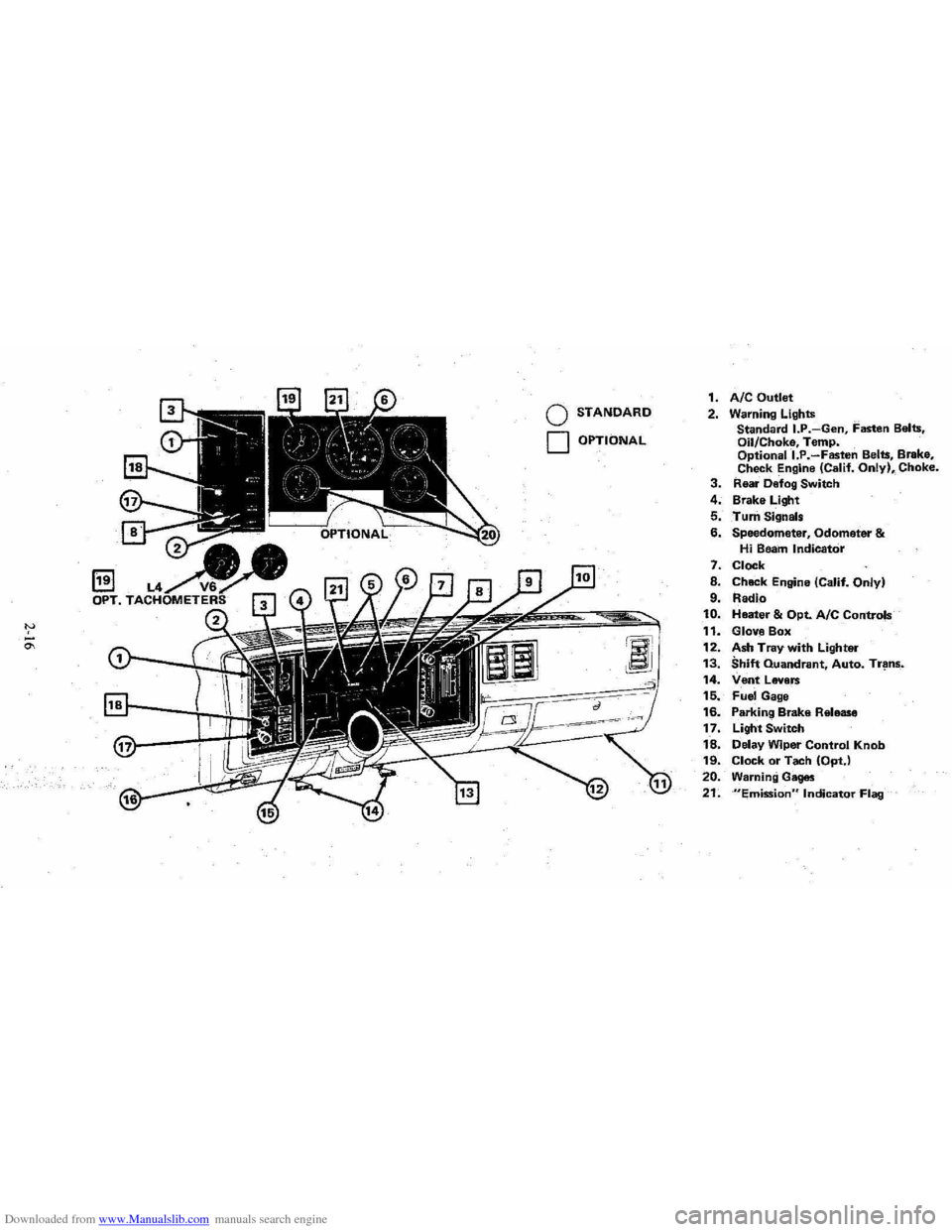
1. AIC Outlet 2. Warning Lights
Standard I.P.-Gen, Fasten Belts.
Oil/Choke, Temp.
Optionall.P.-Fasten Belts, Brake,
Check Engine (Calif. Only), Choke. 3. Rear Defog Switch
4. Brake Light
5. Turn Signals
6. Speedometer, Odometer & Hi Beam Indicator
7. Clock
8. Chack Engine (Calif. Only)
9. Radio 10. Heater & Opt. Ale Controls
11. Glove Box
12. Ash Tray with Lighter 13. Shift Quandrant, Auto. Tr~ns_.
14. Vent Levers 15. Fuel Gage
16. Parking Brake Release
17. Light Switch
18. Delay Wiper Control Knob 19. Clock or Tach (OptJ
20. Warning Gages
21. "Emission" Indicator Flag
Page 34 of 95
Downloaded from www.Manualslib.com manuals search engine Oil/Choke Indicator Light
This light will c0!TIe on to provide a "bulb check", w hen the igni tion is turned on, but sh Qu19 go out after the _ engine is started. If tight fails to
come on wit h ignitio~ turned on, it could indicate a burned out bulb , a
defective electric choke hea ter circuit (on L4 and V6 engines), or a blown
instrument lamp fuse. Have system repaired if light does not come on d min g ch eck .
Occa sionally. this light may flicker momentarily while the engine is running. Should this occur, CHECK EN GINE OIL LEVEL as outlined in Section 5,
"Checking Oil Level." If the light comes on continuously, pull over toa safe place and STOP THE ENGINE until the source of trouble can be loca ted and corrected.
The source of tro uble could be any of the following:
• Loss of engine oil press ure (cbec k eng ine oil level).
• Blown choke heater fuse.
• Loss. of electric choke heate r voltage.
Continuing to run the engine with an illuminated oil pressure light can cause
serious engine damage or unusu ally high exhaust system temperature which can
r esult in serio us damage to the
vehicle. Pull over to a safe place and STOP THE
VEHICLE IMMEDIATELY AND SHUT OFF ENGINE. If the light flashe s
momentarily , ch
eck engine oil leve l as outlined in Sectio n 5 of thi s manu al
Choke Warning Indicator Light
On some vehicles equipped with the optiona l oil pressure gage, an amber choke
warning indicator light replaces the red oil pressure indicator light in the
instrument cluste
r. If this light comes on, indicating loss of electric choke heater
volta
ge, have your authoriz ed Dea ler .locate and correct th e tro uble as soon as
p ossib l
e.
Generator Indicator Light The red ligh t GEN will go on when the ignition key is in the "run" _posit ion, but
before the engi ne
is started. After the engine s tarts, the light should 'go out and
r e m ain out .
If th e light remains on when en gine is running , have your Authorized
D eale r loca te and correct the troubl e as soo n as possibl
e.
Engine Temperature .Indicator Light This indicator light is provided in th e instrument cluster to quickly warn of an
overh eated en gi ne. With the igniti on switch in the START position, the red
TEMP indicator (hot light) will light to let you know that it is operati ng prope rly.
When the engi ne is started ;-th e re d light will go out imm ediate ly. It wilUight up
a t n o other time unleSS for some reason the engine reaches a dangerously high ope ra tin g temperature . 1f the light comes on during extreme driving condition s,
such as an exte nded idle, see "E ngine Cooling
System" on page 3-3. Glance at
th e instrument cluster frequently as you drive to see if this
ligh t is on.
Brake System Warning Light
The regular braking system is a dual system designed so that one part will provide
some braking action if there is a loss of hydraulic pressure in the other part of
the system. The system has a "Brake" warning light loca ted in the instrum ent
pane\.
• To serve as a reminder , the "Bra ke" lig ht is designed to come on while the
park ing brake is se t and the ignition key
is on.
• The light is also designed to come on briefly during engine starting so you
can chec k that the bulb is okay.
• Have the system repaired if the light does not come on during engine starting
o r when the parking brake
is set. 2-17
Page 35 of 95
Downloaded from www.Manualslib.com manuals search engine • This warning light docs no t do away with the need f or ~rake il),s.-pectio n and
maintenanc e. The brake fluid level must be checked regularly . See yo ur
Maint enance Schedule folder for
other brake checks.
If th e light comes on and stays o n when the ig nition key is on, after the brak e
pedal ha s been firmly pushed do wn, it may mean that there is somethin g wrong
wit'h one part of the brake system.
Wh at 10 do:
I. C heck to see that the pa rkin g brake has been released. If it has been ...
2. Pull off the road and sto p ca refully. And rememb er that:
• Stopping di stan ces may be longer .
• You may ha ve to pu sh hard er on the ped al.
• The pedal may go down farther {han no rm al.
3. Tryout the brake s by sta rrin g and stopping on the ro ad shoulder--then :
• If you judge it to be safe, drive cautiously at a safe speed to the neat est
dealer for repair , or
• Have vehicl e to w ed to dealer for repair .
Co ntinu ed dri ving with o
ut getting necessary re p a ir s co uld be dangerou s.
"EMISSIONS" INDICATOR
On so me cars, the word "EMISSIONS" is des ig ned to appear in a window in the spe ed om eter faceat certain int~rvals. This is a reminder that maintenan ce se rv ice
mu st
be performed on your ca r. One of two type s' o f se rvice is required :
• On cars equipped with the C-4 System, the oxygen sensor must be replaced with · a new sensor, or
• On
ca rs without the C -4 System, the cataly st in the catalyti c converter must
b e c han ged.
In either case, see yo ur Chl!~rolet dealer fo r se rvice when the "EMISSIONS "
indicat or appears. .
F or more information , see
"C-4 (Computer Contr olled Catalytic Conv erte r)
Syste m " and "Catalyti c Co nverter," both in "Service and Maintenance," Section
5 of thi s manual.
"CHECK ENGINE" LIGHT
If yo ur car has the C-4 System, a "CHECK ENGINE" light on the instrum ent
panel is des ig ned t o come on
during engine starting to le t y ou know th e bulb is
w orkin g. (The light will sla y o n a short time after th e e ngine s tarts .) If th e light
c o m es on whil e
drivin g, se rv ic e to the emi ssion contr ol sy stem may be re quired . Sc:e your Chevrolet deal er as soo n as: possible fo r an in spec tion of the sy ste m .
COlltinu ed driving without having [he C-4System serviced could eventually cause
d am age to the emission control system. It could also affect fuel economy and
driv ability.
See also '; C-4 (Comput er Co ntrolled Catalytic Converter) System" in ;'Ser vic e a nd
Mainte n ance, " Section 5 o f this manual.
Tachometer
The opti onal Tachomet ers indi cat e the speed of th e e ngin e in revoluti ons pe r minute. The indicated number, tim es ](x>o .. gives the engine s peed. Operatil.lg th e
engine w ith the tachom ete r r eading in the color- coded high ~peed area could lead to s~rious engine damage. The re are two tachom .e ter s us ed in the car depending on the e ngine option install ed in your car.
2-18
Page 48 of 95
Downloaded from www.Manualslib.com manuals search engine /
SECTION 3
IN CASE OF EMERGENCY
See also ",Engine Exhaust Gas Caution (Carbon Monoxide),' at the beginning of
"Starting and Operating," Section 2 of this manual.
FOUR·WAY HAZARD WARNING FLASHER
•. Use the warning flasher to warn other drivers any lime your vehicle -becomes
a traffic hazard, day or nighc.
• Avoid 'stopping on the roadway ,if possible.
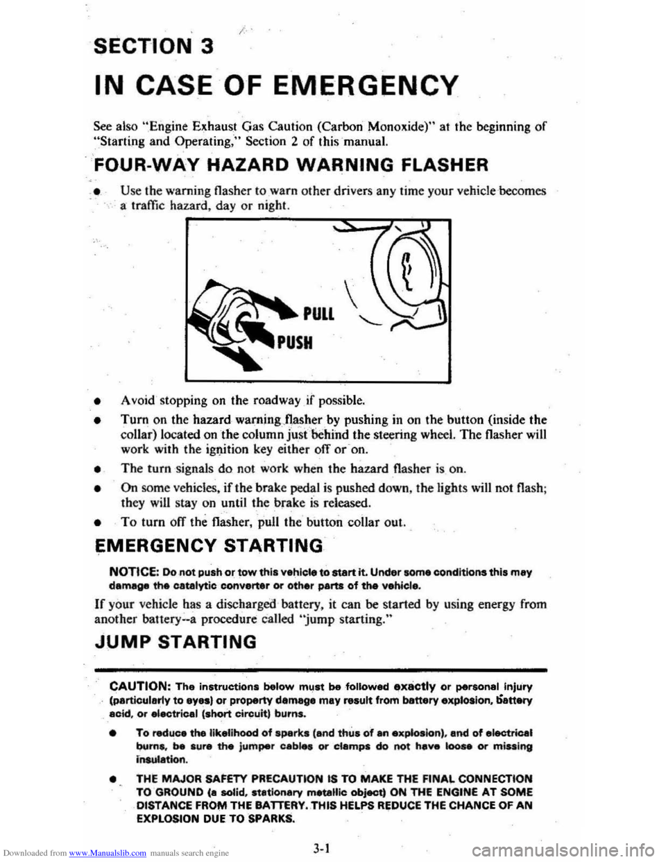
• Turn on the hazard waming"nas~,er by pushing in on the button (inside the collar) located on the column just 'behind the steering wheel. The flasher will work with the ig1J.ition key either ofT or -on.
• The turn signals do not work when the hazard flasher is on.
• On some vehicles. if the brake pedal is pushed down, the light s will not flash ;
they will stay on until the brake is released .
• To turn ofT the flasher, pull the button collar out ..
EMERGENCY STARTING
NOTICE: Do not push or tow this vehiele to start it. Under some eonditions this may damage the catalytic converter or other parts of the vehicl ••
If your vehicle has a discharged battery. it can be started by using energy from
another bauery .. a procedure called "jump starting."
JUMP STARTING
CAUTION: The instructions below mllst be followed ..,x8ctly or personal Injury (particularly to eyas) or property damege may result from banery explosion, ';-attery acid. or "ectrical 'short Circuit, burns.
• To reduce the likelihood of sparks 'and thus of an exp&oslon) , and of electrical
burns. be sure the jumper cab," or ciampa do not hev. 100 .. Of m;uing insulation.
•
THE MAJOR SAFETY PRECAUTlON IS TO MAKE THE FINAL CONNECTION
TO GROUND (a solid, stationary metallic object) ON THE ENGINE AT SOME DISTANCE FROI'II THE BATTERY .. THIS HELPS REDUCE THE CHANCE OF AN EXPLOSION DUE TO SPARKS.
3-1
Page 49 of 95
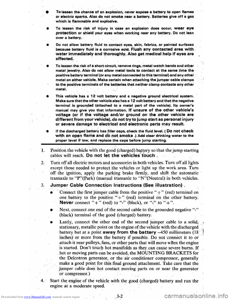
Downloaded from www.Manualslib.com manuals search engine • To lessen the chance of an explosion, never expose a battery to open flames
or electric sparks. Also do not smoke near a ,battery. Batteries give off a gas which is flammable and explosive.
• To lessen the risk of injury incase an explosion does occur, wear eye protection or shield your eyes when working near any battery. Do not lean over a battery.
• Do not allow battery fluid to contact eyes, skin, fabrics, or painted surfaces
because battery fluid is a corrOsiVe acid. Flush any contacted area with water immediately a,nd thoroughly. Also get medical help if eyes are affected.
• To lessen the riskofa short circuit. remove rings, metal watch bands and otl:ler metal jewelry. Also do not allow metal tools to contact at the same time the positive battery terminal (or any metal connected to this terminal) and any other metal em either "ehicle. Make certain when attaching the jumper cable clamps rothe positive terminals of the batteries that neither clamp contacts any other metal.
• This
vehicle has a 12 volt battery and a negative ground electrical system. Make sure that the other vehicle als~ has a 12 volt battery and that the negative terminal, is .'grounc::ted(attached to a metal, part of the vehicle). Its owner's manual may give you that information, If unsure of the other vehicle's voltage (or if the voltage and/or ground on the other vehicle are different from your vehicle). do not try to jump startas personal injury or severe damage to electrical and electronic parts may result.
• If the discharged battery has filler caps. check the fluid level. ( 00 not check with an Op~tn flame and db not smoke .) Add clear drinking water to the proper level if low, and replace the caps before jump starting.
I. Position, the vehicle with'the good (charged)ba,.ttery so that the jump starting
cables will reach.
Do not let the vehicles t"ouch.
2. Turn off all electric motors and accessories in both vehicles. Turn off all lights
except those needed to protect the vehicles or light up the work area. Turn
off the ignition, apply the parking brake firmly, and shift the automatic transaxleto "p"o.?ark) (manual transaxle to "N"(Neutral) in both vE-hicles.
3. Jumper Cable Connection Instructions (See illustration) .
• Connect the first jumper cable from the positive" +" (red) terininal on
one battery to the positive "+" (red) terminal on the other battery.
Never, connect "+" (red) to "~" (black), or '\" to "+".
• Next, connect one end of the second cable to the grounded negative "."
(black) tenninal of the good (charged) battery.
• Lastly, connect the othetend of the second jumper cable to a solid,
stationary, metallic point on the engine of the vehicle with the discharged
battery but at a
point away from the battery --450 millimeters (18 '1
inches) or more from the battery if possible. Do not connect it to or attach it near pulleys, fans, or other parts that will move wHen the engine
is started. Don't touctt hot manifolds as they _can cause severe burns. If hot or moving parts can be avoided, the MOUNTING BRACKETS for
the Delcotron generator,
or the air conditioner compressor, ,generally
make a good point for-this final ground attachment. Take care that the
jtimper cable does
hot contact moving parts on or near the generator
or compressor.)
4. Start the engine of the vehicle with the good (charged) battery and run the
engine at a moderate speed.
3-2
Page 51 of 95
Downloaded from www.Manualslib.com manuals search engine • pull over-to a 'safe p'late and stop (he car:-=Set the parking brake and shift to "P"(Park) (with a manual transaxle. shift to Neutral first, then set the parking
brake).
• DON'T TURN OFF THE ENGINE AND DON'T INCREASE THE ENGINE SPEED~ Let the engin e run at normal idle speed for two or three
minutes.
If the
''TEMP'' light still doesn't go off (or the gage needle doesn't start to drop) , NOW TURN OFF THE ENGINE and proceed as follows.
CAUTION: Keep henda, tools end clothing awey from'the engine COOling fen to help prevent personal Injury. This fen ia electric end can come on whether or not the eR8ine is runnirl'jJ. The fan Cen etert eutomatically in reapon .. to a heet ~, wrth the ignitkNl in ~Run."
• Lift the engine hood. Look at the coolant level.in the "see through " coolant
recovery tank. The coolant level should be at or above the "Fun Hot" mark
o n the tank.
If it looks like the coolant is boiling, wait until it stops before
proceeding You should :not need to remove the radiator cap to check the
coolant level and it can be dangerous if the coolant is still hot. See the
following Caution.
CAUTION: To help avoid the dange, of being burned:
• cia not remove the coolent recov.ry tank cap while the coolant is boiling.. and
• cia not remove the .rad~:_c.p white the engine end radiator are atill hot.
Scelding fluid and ateam can be blow, Qut under presau,.. If either cap ia taken off too soon.
• If the coolant level is low:
• look for leak s at the radiator hoses and connectio ns, heater hoses and
connections. radiator, and water pump.
See that the water pump belts
are not
brok~ or otT the pulleys and that the fan runs when the engine is running and theUTEMP" light ison (or the gage needle is in the
warning zone).
• add coolant to the recovery tank.
If the level in the recovery tank is at the correct level and the "TEMP" light (gage) still comes on, air may be-trappedin the, cooling system . This may prevent coolant
from returning to the radiator.
In this case. you may have to add coolant directly
to th e radiator.
See "Coolant Replacement" in "Service and Maintenance," Section 5 of this manual. Follow steps I and 10 for the correct way to remove
the radiator cap and add coolant to the radiator.
After the "TEMP" light is out (or the gage needle is out of the warning zone).
resume driving
at a reduced speed. Return to normal driving after about ten
minutes if the light does not come back on (or the gage needle does not go back
into the warning
~one).
J.4
Page 52 of 95
Downloaded from www.Manualslib.com manuals search engine I COMPACT SPAul
*( ~
Y' v.
~
I ~-C( -"""-c I NO SPARE I • G@1J;"~j ((?)lie, __ ,". ::..-_~.c_
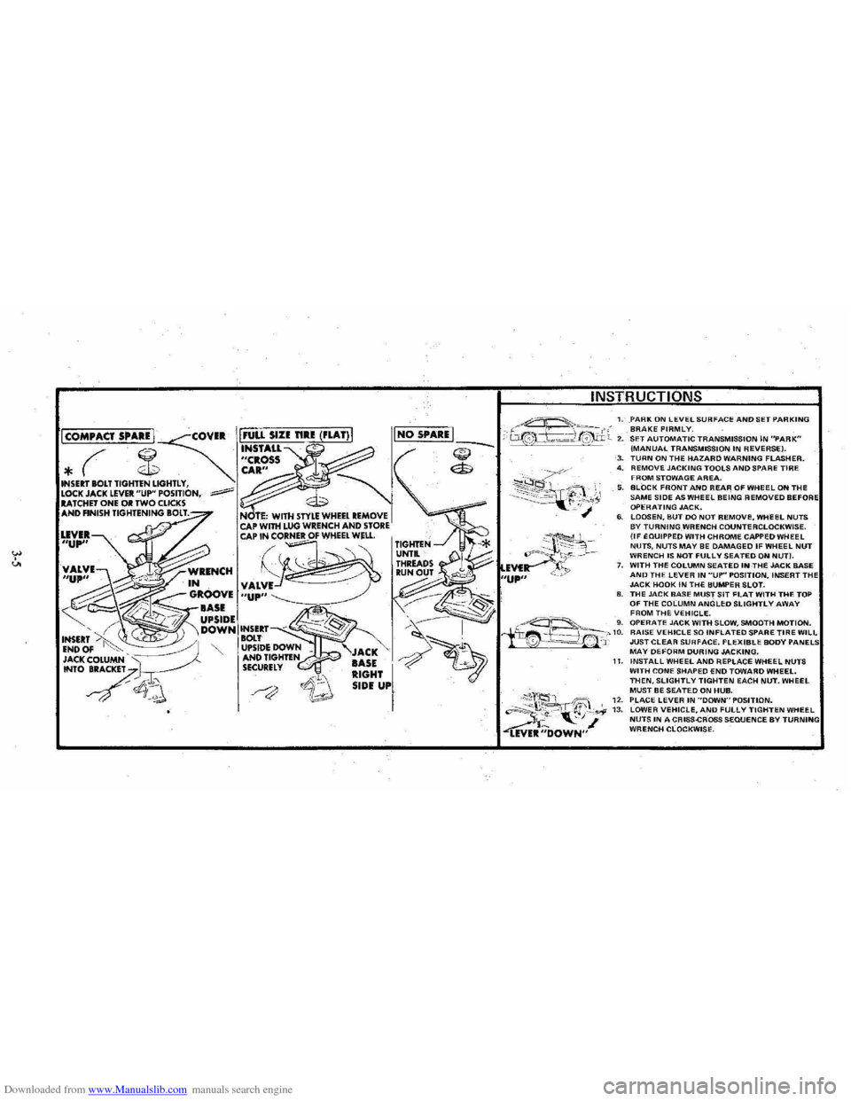
1. PARK ON lEVEL SURFACE AND SET PARKING BRAKE FIRMLY. 2. SET AUTOMATIC TRANSMISSION IN "PARK" (MANUAL TRANSMISSION IN REVERSE). ~ ($
~~~~?~;y,
3. TURN ON THE HAZARD WARNING FLASHER. 4. REMOVE JACKING TOOLS AND SPARE TIRE FROM STOWAGE AREA. 5. BLOCK FRONT AND REAR OF WHeEL ON THE SAME SIDE AS WHEEL BEING REMOVED BEFO OPERATING JACK. 6. LOOSEN, BUT DO NOT REMOVI:, WHEEL NUTS BY TURNING WRENCH COUNTERCLOCKWISE. (IF EQUIPPED WITH CHROME CAPPED WHEEL NUTS, NUTS MAY BE DAMAGED IF WHEEL NUT WRENCH IS NOT FULLY SEATED ON NUT). 7. WITH THE COLUMN SEATED INTHE JACK BASE AND THE LEVER IN "UP" POSITION, INSERT TH JACK HOOK IN THE BUMPER SLOT. 8. THE JACK BASE MUST SIT FLAT WITH THE TOP OF THE COLUMN ANGLED SLIGHTLY AWAY
I
FROM THE VEHICLE. ~---'-_ 'g. OPERATE JACK WITH SLOW, SMOOTH MOTION. iir~f~~_-'-'10. RAISE VEHICLE SO INFLATED SPARE TIRE WILL '0 --=-==!.~' 'J: JUST CLEAR SURFACE. FLEXIBLE BODY MAY DEFORM DURING JACKING.
;\;'2, 'ift;" "~~t. "-', ~ ~R;;'OWN"
11. INSTALL WHEEL AND REPLACE WHEEL NUTS WITH CONE SHAPED END TOWARD WHEEL. THEN. SLIGHTLY TIGHTEN EACH NUT. WHEEL MUST BE SEATED ON HUB. 12. PLACE LEVER IN ··DOWN"POSITlON. 13. LOWER VEHICLE. AND FULLY TIGHTEN WHEEL NUTS IN A CRISS-CROSS SEQUENCE BY WRENCH CLOCKWISE.
Page 54 of 95
Downloaded from www.Manualslib.com manuals search engine • The compact spare .tire and wheel are design ed for use with each
other. The compact spare tire should not be mounted on any other
type of wheel, and the compact spare wheel should not have any
other type of tire mounted on it. Also, do not try to use wheel covers or trim rings on the compact spare wheel since they will not fif" If
s u ch u se is attempted, damage to these items or other vehicle compo~
nent s may occur.
• Do 1I0t use tire chains with your compact spar e tir e. Because of .the smaller lire size, a tire chain will no t fit properly . This could cause damage to the car and result in loss of the cha,in.
Towing
Prop er equipment must be used 10 prevent damage to ve hicle s during any towing .
State ,(.,rovincial in Canada) ,and l~~l laws which apply to Cars in tow must be
followed '. Get detailed towing instructions from your deale r.
Your
vehicle may be towed on all fo ur wheels, at speeds less than 35 mph (60
km /h) , for distances u'p 1O 50 miles ( 8 0 kilometer s). pro vided the driveline and
steering are normally operabl
e. For such towing the steering must be unlocked ,
tran saxle in neutral , and the parking brake released . Co
nnec t to main structural
part s of th~ car; Do NOT attach to , bumpers or brackets . Remember also that power assist for brakes and steering will not beavailable ' when the, engine is ofl
If the car' is to be towed by a 'wrecker, use only equipm~nt designed for this
purpos
e, following the instru ction s of the wrecker manufacturer.
A safety chain system must
be used forall towing .
Freeing Vehicle from Sand. Mud. Snow or Ice
If your car gets stuck in sa nd , mud , snow or ice , move the s hift lever on aut om atic
tr ans ax le models from "D"(Orive) to "R"(Reverse) in a repeat pattern. (On
manual transaxle models, move the shift lever from First or Second to Rever se.)
Apply a
light pressure to the acce lerator pedal while the transaxle is in gear.
Remove your
foot from the;: accelerator while shifting . Do not race the engine.
For best traction, avoid spinnin g the wheels. Incorrect rocking of your car while it is stuc k may result in damage to vehicle components.
CAUTION: 00 not spin the wh •• ls faster than 20 mph (35 km/ h) . Personal injury end damage (including tire and/Of transexle failure) rna)' result from excessive wheal spinning.
If vehide re mains stuck after several roc king attempt s, s eek other assistan ce.
Also 'see the Notice under
"Automatic Transaxles" i,n "Steering Column
Contro ls" Section 2 of this manu al.
. 3-7
Page 65 of 95
Downloaded from www.Manualslib.com manuals search engine USE Tlltst: SAE VISCOSITY GItotoDH
I , , , cl.
*
::0';'~ ,.,..~,: , , , ,
I
lOW , , , ,
,
I I I I , . , " • '" ,~, ." ., , " " " ~ lVitPl .... 1Ul:( lAN<* YOU ElU'EClltfOll( NUT OIl CHANG(
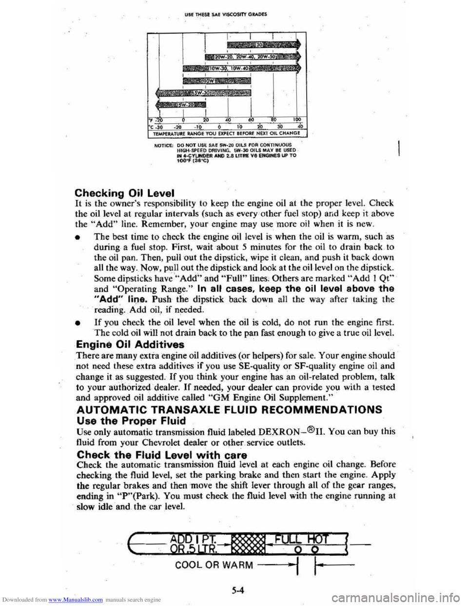
NOTICE: 00 NOT USE SA~ 5W-2 0 OilS fOA CONTINUOUS HIGH-SPEEQ OAIVING. 1,iW-30 OILS MAY III USED .. 4.CYIJNO!!R AND 2.lIll1AE VII EItClMES UP TO 104)
the oil level at regular intervals (such as every 'o ther fuel stop) and keep it above
th e "Add" line. Rem ember, your engine may use more oil when it is new .
• The best time to check the engine oil level is when the oil is warm, such as
during a fuel stop. First, wait about 5 minutes for the oil to drain back to
the oil pan, Then, pull out the dipstick, wipe
it clean, and push it back down
all the way . Now , pull out.th e dipstick and look at the oil-level on the dipstick.
Some
dipSlicks have "Add" and "Full" lines , Others are marked "Add! Qt"
and "Operaling Range." In all cases, keep the oil level above the
"Add" line. Push· the dipstick back down all the way after taking the
reading. _ A ·dd oil , if needed.
• If you check the oil level when the oil is cold, do no t run the engine first. The cold oil wilJ not drain back to the pan fast enough to give a true oil level.
Engine Oil Additives
There are many extra engine oil additives (or helpers) for sale. Your engine should
not need these extra additives if you use SE-quality or SF·quality engine oil and
change
it as suggested. If you think your engine has .an oil-related problem, talk
to your authorized dealer.
If needed, your dealer can provide you with a tested
and approved oil additive called "GM Engine Oil Supplement."
AUTOMATIC TRANSAXLE FLUID RECOMMENDATIONS
Use the Proper Fluid Use only automatic transmission fluid labe led DEXRON-®II. You can buy this
fluid from your Chevrolet dealer or
othe~,'service outlets.
Check the Fluid Level with care Check the automatic transmission fluid level at each engine oil change. Before
checking the fluid level, set the parking brake and then start the engine. AppJy
the regular brakes and then
'mov e the shift lever through all of the gear ranges,
ending in
"P '·(Park). You must check the fluid level with the engine funning at
slow idle and the car level.
I-c ..... --=---=..,~ ..... B9"""5IL.u;~~"-·, __ .........,; ..... _·F_%¥-W+--T -l{
COOL OR WARM -j ""I ,~-
5-4
Page 74 of 95
Downloaded from www.Manualslib.com manuals search engine CAUTION: BefOf"e Installing wheels. remo';.'~-~y build.up of corrosion on the wheel mOOnti_ng surfllce.and brake .drum or disc mounting surface by scrllping and wire brushing~-Installing ~h •• ls without good metal·to-metal contact at the mounting surfaces can cause whe.lnuts to loosen. which can later allow a wheel to c;ome off while the vehicle is moving. possibly causing loss of control.
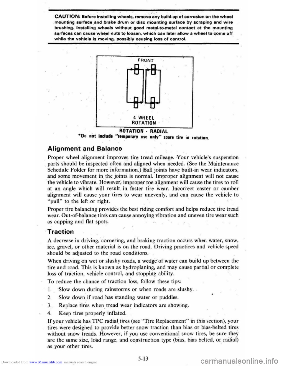
FRONT
4 WHEEl ROTATION
ROTATION· RADIAL "00 .at induM-'''tm,erMY use Daly" sure tire in rotation .
Alignment and B.alance
Proper wheel alignment improves tire tread mileage . Your vehicle's suspension
. parts should be inspected often and aligned when needed. (See the Maintenance
Schedule Folder for m ore information.) Ball joints have built-in wear indicators,
and some movem ent in th~ joint s is normal. ' Improper alignment will not cause
the
vehicle to vibrate. However, improper toe alignment will cause the tires to roll
at an angle which will result in faster tire wear. Incorrect caster or camber
alignment will cause your tires to wear unevenly, and can cause the vehicle to
"pull" to the left or right.
Proper tire balan cing provides the best riding comfort and helps reduce tire tread
wear. Out--of-balan ce tires -can .cause annoying vibration and uneven tire wear such
as cupping and
flat spots.
Traction
A decrease in driving. cornerin g, and braking traction occurs when water, snow,
ice, gravel ,
or other material is on the road. Driving practices and vehicle speed
should be adjusted to the road condition~.
When driving on wet or slushy roads, a wedge -of water can build up between the
tire and road. This is known as hydroplaning, and may cause partial or complete
l oss
of traction, vehicle control, and stopping ability.
To reduce the chance of traction loss, follow these tips:
I. Slow down during rainstorms or when roads are Slu shy .
2. Slow down if road has standing water or-pUddles.
3. Replace tires when tread wear indicators are showing.
4 . Keep tires properly inflated.
If your vehicle has TPC radial.tires (see "Tire Replacement" in this section), your
lir es were design ed to
provide _ better snow tracti on than -bias or bias-belled tires
without snow treads. However , iF . yo u use conventional snow tires. be sure they
are the same size. loa d range, and construction type (bias, bias belted,
or radial)
as your other tire
s.
5-13