maintenance schedule CHEVROLET CITATION 1980 1.G User Guide
[x] Cancel search | Manufacturer: CHEVROLET, Model Year: 1980, Model line: CITATION, Model: CHEVROLET CITATION 1980 1.GPages: 95, PDF Size: 21.48 MB
Page 63 of 95
Downloaded from www.Manualslib.com manuals search engine CATALYTIC CONVERTER
. The catalytic converter is an emission control device added to the
exhaust system to reduce exhaust gas pollutants. The converter
contains a ceramic material coated with noble metal catalysts. To prevent
contamination of the cata lysts,
unle~ded gasoline must be used. Unleaded gasoline
also reduc es combustion chamber deposits and exhaust system corrosion.
The catalytic converter requires the use of unleaded gasoline. Use
of leaded gasoline will cause the converter to lose its effectiveness for emission control. On some engines, the catalyst must be changed at cer tain inter vals in orde r for
the emissio n control system to continue to operat e properly. The change intervals
are speci fied in Section C of the Maintenance Schedule folder.
On cars that require this catalyst change, the word "EMISSION" will
appear on an indicator in the speedometer face at the specified change
in terval
s. This is a reminder that the cata lyst must be changed. (If the indicator does not appear, your car does not need this catalyst change).
Your Chevrolet deale r will perform the lirst cataly st cha nge at no charge, whether yO'u are the first owner or a subsequent owner. As part of this service, the indicator
should be reset to appear
at the next specified chang e interval. To help prevent
damage:
1. Keep your engine properly maintained. Engine malfunctions involving th e electrical, carburetion or ignition systems may result in unusually high
conve rter and exhaust system temperatures .
Do not keep driving your vehicle if you detect engine misfire. noticeable loss of
perform,8nce. or other unusual operating conditions. Instead, have it serviced promptly. A properly ···maintained engine will he lp avoid
malfunction s that could damage the converter.
It will also help provide good
emissio.n cq!).,trol and gasoline economy. See the Maintenance Schedule folder
for inform ation on inspecting a
nd maintaining the engi ne. exhaust system.
and other compone nts.
2 .
Do not drive through, idle, or park your vehicle over combustibl e materials,
s u ch as grass
or leaves. They could 'touch the hot exhaust system and ignite.
3. Do n o t push or tow this vehicle 10 stan it. This cou ld damage (he converter.
Disregarding this information could damage the catalytic converter, the vehicle,
or nearby property.
C-4 (COMPUTER CONTROLLED CATALYTIC CONVERTER)
SYSTEM If your new car was purchased in California, it has a special emission control
system, called
the C-4 (Computer Co ntrolled Catalytic Converter) System. The C4 System monitors the exhaust stream with an oxygen sensor. Based 4
on senso r signals, the electr onic control module adjusts the carburetor
air~fuel ratio as needed. It is very important to use only unleaded gasoline
in cars with
the C-4 System. Leaded gasoline will damage the oxygen
sensor. which may affect emission
control, fuel economy and drivability.
Some cars equipped with the C-4 System need an oxygen sensOr change
at the intervals specified in Section C of the Maintenance Schedule folder.
On these cars, an oxyge n sensor maintenance reminder is included in the
instrument paneL The word "EMISSIONS" is designed to appear in a
window in the speedometer face at the intervals outlined in the Maintenance
Schedule folder. The "EMISSIONS " indicator is a reminder that the oxygen
sensor must be repl aced with a new sensor.
Such replacement is necessary
in order to maintain the correct operation of the emiss ion control system.
The indicator must be reset as part of this service.
5-2
Page 66 of 95
Downloaded from www.Manualslib.com manuals search engine NOTICE: You cannot read the correct fluid level if you have just driven the car for a long time at high speed, in city traffic in hot weather, or if the car has been pulling a trailer. Wait. until the fluid has cooled down (about 30 minutes).
Remove the dipstick located on the driver's side forward of the cowl. Carefully
touch the wet end of the dipstick to find out if the fluid is cool, warm or hot. Wipe
it clean and push it back in until the cap seats. Pull
out the dipstick and read the
fluid level.
• If it felt cool or warm (about room temperature), the level should be
between the dimples above the "Full" mark.
• If it was too hot to hold. the level should be at or in the hatched area.
Add just enough DEXRON-®n fluid to fill the transaxle. It takes only 0.5 liter
(one pint)to raise the level from "Add" to "Full" with a hot transaxle.
Do not overfill the transaxle. Overfilling can cause foaming and loss of fluid, which
could result in transaxle damage.
Automatic Transaxle Drain Intervals
Change the transmission fluid and change the filter (or clean the screen) as
outlined in Section
A of the Maintenance Schedule folder.
ELECTRIC FAN
CAUTION: Keep hands, tools, and clothing away from the angine cooling fan to help prevent personal injury. This fan is electric and can come on whether or not the engine is running. The fan can start automatically in response to a heat sensor when the ignition is in the "Run" position.
ENGINE COOLING SYSTEM
The coolant recovery system is standard. The coolant in the radiator expands with
heat, and the overflow collects in the recovery tank. When the system cools down,
the coolant
is drawn back into the radiator.
The cooling system was filled at the factory with a quality coolant that meets
GM Specification 1899-M. The cooling system is designed to use coolant (a mixture
of water and ethylene glycol antifreeze) rather than plain water. The coolant
solution should be used year round. It has many advantages, such as:
• provides freezing protection down to _37°C, (-34°P)
•
provides boiling protection up to 128QC, (262°P)
•
protects against rust and corrosion in the cooling system,
• maintains the proper engine temperature for efficient operation and emission
control, and
• allows proper operation of the coolant temperature light (or gage).
See Section A of the Maintenance Schedule folder to find out when the coolant
must
be replaced.
COOLING SYSTEM CARE
Check the cooling system at regular intervals, such as during fuel stops. You
usually do not need to remove the radiator cap to check the coolant level. Lift
the engine hood and look at the "see through" coolant recovery tank. When the
engine
is cold, the coolant level -should be at or slightly above the "Full Cold"
mark on the tank. When the engine has fully warmed up, the level should be at ')r slightly below the "Full Hot" mark on the tank. If the coolant level is low,
5-5
Page 67 of 95
Downloaded from www.Manualslib.com manuals search engine remOve tlie cap on the coolant ~ecove~y tank : Add to the tank enough of a 50 150 . mixture of w ater and a g ood quality eth)dene glycol antifreez e to bring the level
up to the .
proper mark. Put the cap bac k on the tank .
Certain
conditi ons; "Such as air trapped in the syste m, may affe ct the coolant level
in
the radiator. You sho uld ch ec k the co olant ·Ievel ·in the radiator while you
change the engine oil and the e ng ine is col d. Follow steps I , 8, 9 and 10 und er
"Coola nt Rep lacement" for the correct way to rt!move the radiator cap .an d add
. coolant.
If you have to add coola nt more than f our tim es a yea r (ei ther to th e recov ery
tank
or to the radiat or). see your dealer. for a. c oo lin g system chec k.
NOTICE: If the proper quality antifreeze is used, there is no .nee~ to add extra inhibltOf"s or additives which claim to improve the svstem .. They may be harmful to the proper operation. I)f the system.
Cooling System Service
The cooling syste m should be serviced at the intervals specifi ed inSection A of
the Maintenan ce Sch edule fold er as follows:
I. W ash the radiatqr cap .and filler neck with clean water. See step J of "Coolant
Replacement" to remove rapiator cap. .
2. C hec k the coolant level in the radiator and have it tes ted for freeze proteCtion . Add·· ethylene gly col antifreeze, if needed, to· m aintain freeze protecti on at -37'C(-34'F),
3~ Have ·the coOlin-g sys tem and radiat or cap tested fo r a press ure capacity of
105 kPa (15 psi) . If a repl acement cap is needed"Hse an AC ca'p,or an
equivalent · cap, designed fOl: coolant recovery system ·s and spe cified for your model;
4. Tighten all radiator hose clamps and heater hose clamps and inspect an hose s.
R
eplace the hose s if they are swollen, "checked" or otherwise worn .
NOTICE: Take care when tightenjng·the hose clemps at tMI radiator. Overtightening COUld. bend or collapse .the radiator fittings.
5. Clean the front. of the radiator core and air condit ioning condenser to re m ove
dirt and oth er·objects. Al so clean the auxiliary engine oil andlor transmission -fluid ' cooler if the vehicle has them.
Coolant, Replacement
At the interval s specified in Section A of the Maintenance Schedule folder, flu sh
a
nd refill the cool ing system as follows :
1. Remove the·radiat or·cap when the engin e is ·cool :
•
Turn . t he cap s lowly to the len until ·it reaches a " stop. " Do not press down while turning the cap.
• 'Wait until any rem aining press ure (indicated by a hissing sound) is
reliev ed. then press down on the cap an d continue turning it t(j the left.
CAUTION:· To help ~lVoid the danger of being ,burned, do not remove the radiator cap while the angine and radiator are still hot s.c.lding flutd and steam can be bk)wn out under pressure if the·cap is taken off.too soon.
2. Whe n the cap is re m oved, run the eng ine until the upper radiator hose is hot.
(This shows that the thermostat is open and the coola nt is flow ing through
the . system.)
5·6
•
Page 70 of 95
Downloaded from www.Manualslib.com manuals search engine CAUTION: If the air cleaner is removed during repair or maintenance, be sure to . put It back on correctly. If the air cleaner is not correctly installed, there could be II fire In the engine compartment (if there should happen to be a backfire), or other engine malfunction.
Power Steering System
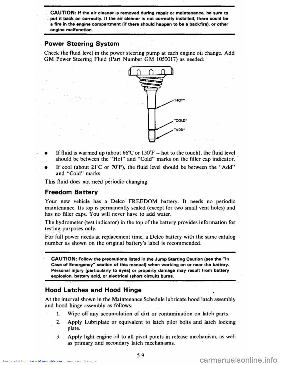
Check the 'fluid level in the power steering pump at each engine oil change. Add GM :Power Steering Fluid, (Part Number GM 1050017) as needed:
, • Ifnuid is warmed up (abo ut 66°C or lSO"F --hot to the to uch), the fluid level
should be between the "Hot" and "Cold" marks on the filler cap indicat or.
• If cool (about 21°C or 70° F), the fluid level should be between the "Add" and "Cold" marks.
This fluid
does not need ' periodic changing.
Freedom Battery
Your new vehicle has a Delco FREEDOM battery. It needs no periodic
maint enance . Its
lOp is permanently sealed (except for two small vent holes) and
has no filler caps. You will never have to add water. .
The hydrometer (test indicat or) in the top of the battery provides information for
testing purposes only.
For full power needs at repla cement time, a Delco battery with ,the same catalog
number as shown on the original banery's label
is recommended.
CAUTION: FoUow the precautions listed in the Jump Starting Cautton {see the "'n Case of Emergency''' section o"f this manual, when working on or near the battery.
Personal injury (particularly to eyes) or property damage may result from battery explosion, battery acid, or electric.1 (short circuit) burns.
Hood latches and Hood Hinge
At the interval shown in the Maintenance Schedule lubricate hood latch assembly
and hood hinge assembly as follows :
1 . Wipe off any accumulation
of dir.t or contamination on latch parts.
2. Apply Lubriplate or equivalent to latch pilaf bolts and latch loc king
plate .
3. Apply light engine oil to all pivot points in release mechanism, as well
as primary
and secondary latch mechanisms.
5-9
Page 73 of 95
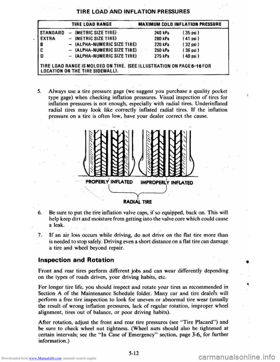
Downloaded from www.Manualslib.com manuals search engine STANDARD EXTRA B C o
TIRE LOAD AND INFLATION PRESSURES
TIRE LOAD RANGE
-(METRIC SIZETIREI -(METRIC SIZETIREI -(ALPHA-NUMERIC SIZE TIREI -(ALPHA-NUMERIC SIZE TIREI -(ALPHA-NUMERIC SIZE TIREI
MAXIMUM COLD INFLATION PRESSURE
240 Ic.Pa 280 kPa 2211 kP. 250 kP, 275 kP,
(35 psi I (41";1 (J2 psil ( 36 psil (40 p.iI
TIRE LOAD RANGE IS MOLDED ON TIRE. (SEE ILLUSTRATION ON PAGES-leFOR LOCATION ON THE TIRE SIOEWALU.
5. Always use a tire pressure gage (we suggest you purchase a quality pocket
type gage) when checking inflation pressures. Visual inspection of tires for
inflation pressures is nol enough, especially with radial tires. Underinflated
radial tires may look like correctly inflated radial tires.
If the inflation
pressure on a tire
is often ·low, have your dealer correct the cause.
, I PROPERlY INFlATED 1MPR0PERl Y INFlATED
l~_~~_~) y RADIAl. TIRE
6. Be sure to put the tire inflation valve caps, if so equipped. back on. This will help keep dirt and-moisture from getting into the valve core which could cause
a leak.
7 .
If an air loss occurs while driving. do not drive on the flat tire more than
is needed to stop safely . Driving even a short distance _on a flat tire can damage
a tire and wheel beyond repair.
Inspection and Rotation
Front and rear tires perform different jobs and can wear differently depending
on the types
of roads driven, your driving habits, etc.
For longer tire life, you should inspect and rotate your tires as recommended in
Section A
of the Maintenance Schedule folder. Many car and tire dealers will perform -a free lire inspection to look for uneven or abnormal tire wear (usually
the result of wrong inflation pressures, lack of regular rotation, improper wheel
alignment, tires out
of balance, or poor driving habits).
After rotation, adjust the front and rear tire pressures (see
"Tire Placard") and be sure to check wheel nut tightness. (Wheel nulS should also be tightened at
certain intervals ; see the
hIn Case of Emergency" section, page 3-6, for further
information.)
5-12
Page 74 of 95
Downloaded from www.Manualslib.com manuals search engine CAUTION: BefOf"e Installing wheels. remo';.'~-~y build.up of corrosion on the wheel mOOnti_ng surfllce.and brake .drum or disc mounting surface by scrllping and wire brushing~-Installing ~h •• ls without good metal·to-metal contact at the mounting surfaces can cause whe.lnuts to loosen. which can later allow a wheel to c;ome off while the vehicle is moving. possibly causing loss of control.
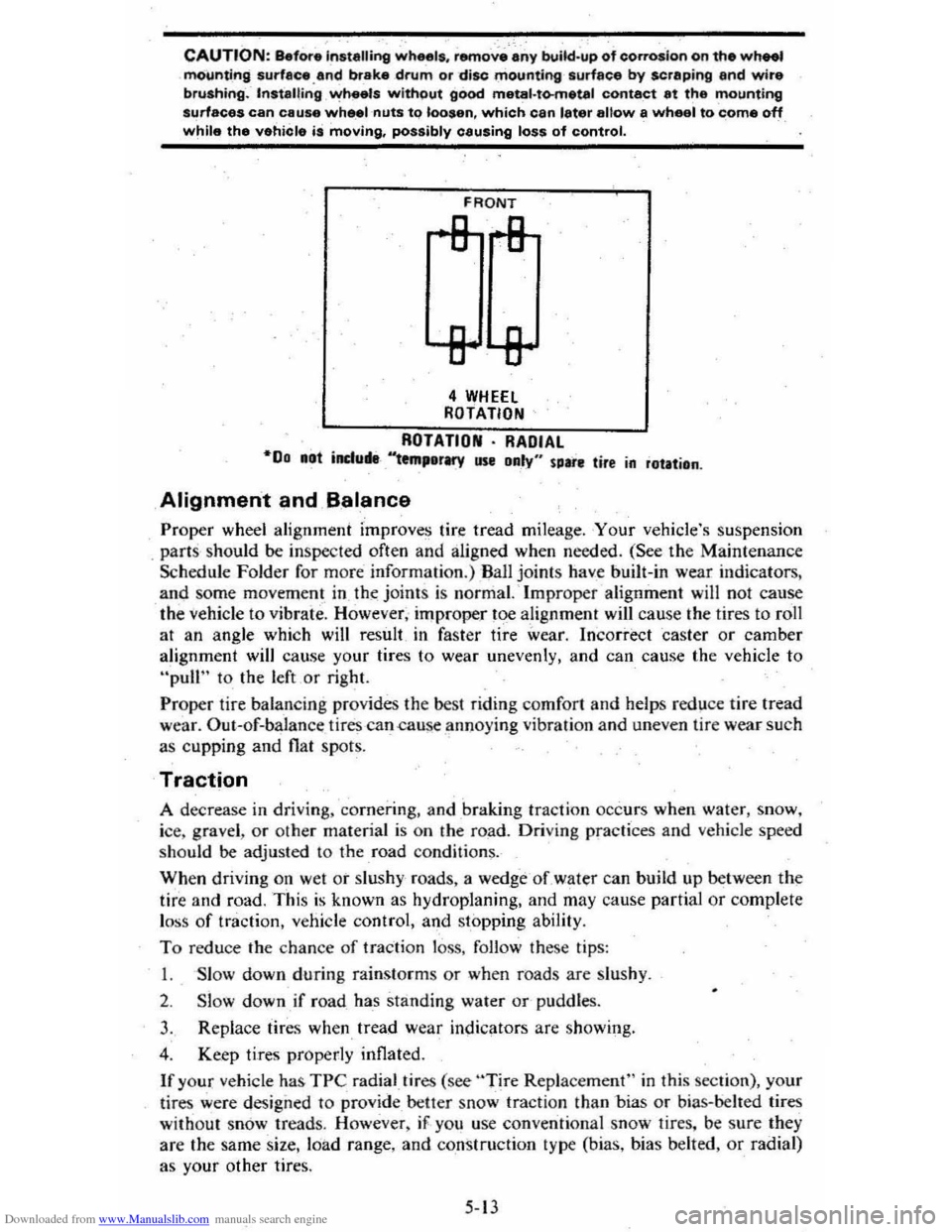
FRONT
4 WHEEl ROTATION
ROTATION· RADIAL "00 .at induM-'''tm,erMY use Daly" sure tire in rotation .
Alignment and B.alance
Proper wheel alignment improves tire tread mileage . Your vehicle's suspension
. parts should be inspected often and aligned when needed. (See the Maintenance
Schedule Folder for m ore information.) Ball joints have built-in wear indicators,
and some movem ent in th~ joint s is normal. ' Improper alignment will not cause
the
vehicle to vibrate. However, improper toe alignment will cause the tires to roll
at an angle which will result in faster tire wear. Incorrect caster or camber
alignment will cause your tires to wear unevenly, and can cause the vehicle to
"pull" to the left or right.
Proper tire balan cing provides the best riding comfort and helps reduce tire tread
wear. Out--of-balan ce tires -can .cause annoying vibration and uneven tire wear such
as cupping and
flat spots.
Traction
A decrease in driving. cornerin g, and braking traction occurs when water, snow,
ice, gravel ,
or other material is on the road. Driving practices and vehicle speed
should be adjusted to the road condition~.
When driving on wet or slushy roads, a wedge -of water can build up between the
tire and road. This is known as hydroplaning, and may cause partial or complete
l oss
of traction, vehicle control, and stopping ability.
To reduce the chance of traction loss, follow these tips:
I. Slow down during rainstorms or when roads are Slu shy .
2. Slow down if road has standing water or-pUddles.
3. Replace tires when tread wear indicators are showing.
4 . Keep tires properly inflated.
If your vehicle has TPC radial.tires (see "Tire Replacement" in this section), your
lir es were design ed to
provide _ better snow tracti on than -bias or bias-belled tires
without snow treads. However , iF . yo u use conventional snow tires. be sure they
are the same size. loa d range, and construction type (bias, bias belted,
or radial)
as your other tire
s.
5-13
Page 90 of 95
Downloaded from www.Manualslib.com manuals search engine Switch Headlights .... TEMP (Temperature) .. Locks Door ...
2~19 2-17 1-2
Ignition ............................................. .. 2-5 1-1 2-2
2-25 Keys .. Theft Protection .. Lowering Seats .. Love Seat, Child & Infant: .. Lugglige/Cargo Capacity ... Luggage Rack ... Maintenance Record .. Maintenance Schedule .. Manual Transaxle Clutch Adjustment. .. .
1-10 5-11 2·29 7-12 5-.1
Maintenance ........................................... . 5-8
5-8
2-11
2· 10 2-12 4-1 4-5
1-3
Operating Tips .. Operation .. Shift Speeds. Metal Cleaners .. Metal Damage, Body ... Mirrors, Rearview .. Mobile Radios-. Monoxide Caution, Carbon .. . 2-25 2-1
2-1 2-2
2-2
2-15 Muffler ............................................... . New Car Break-In Period Octane Rating, Gasoline ... Odometer Oil, Engine Capacity .. Change Interval.. Dipstick ... Filter ... PreSsure Gage .. Pressure Light... Recommendation (Gas) .. OIL Light.. Openings, Roof... Opening The Hatchback ... Hood .. Windows ..
6-.1 5-3 (inside Back Cover) 5-3,7·1 2·1-9 2-17
5-3
2-17 (See "Roofs")
2·26 (Inside Back Cover) 1-5 Operating Speeds, New Car... 2-2 Operating Tips Fuel Economy.. 2-4 Trailer Towing.. 1-13 Transaxle... 2-9 Ventilation System.. 2.20 Operation in Foreign Countries.. 2"3 Outside Rearview Mirror.. 1.3 Overheating, Engine.. 3-3 Overseas Operation.. 2.3 Owner Assistance.. 6-1 Owner's Record... 7-11 Oxygen Sensor., 5.2 Paint Care.. 4-4
Paint Damage .. Parking;. Parking Brake .. Parking Lights .. PCV Valve & Filter .. Peda'·TI"avel, Brake ... Pedal Travel, Clutch .. Polishing & Waxing .. Pollution Control Power
4-' 2-. 2-14 7-3 7·2 2-14 5~8
.-. (See "Emission Contron
7-8
Antennas Brakes .. Door Locks .... Seats ... Steering Pressure, Oil Light ... Pressure. Tire Inflation ... Pulse Wiper ...
2-25
2-14
1-2 1-' 2·12
2-15
5-11
2-7
Pushing to Start ................................ .. 5-2 Radiator Antifreeze (Coolant) .. Cap, Prassure .. Checking Level .. Overheating .. Thermostat...
Radios & Antennas ... Raising Seats ... Rear Cargo Cover ...................... .. Compartment .. . Window Defogger .. Trailering .. Rearview Mirrors .. Reclining Seats .. Recovery Tank, Coolant .. Release
Hatc.hback
Hood .. Seatback Latch ... Reminder Lights ....
Replacement Fasteners
5-5 5-. 5-5 3-3 5-7
2-23 -2-25
2-25
2-:27
2-2,2-28 2-21 '·11 1-3 1-' 5-5
2-25 (Inside Back Cover)
1-' (See "Lights") 5-1
5-1 Replacement Maintenance Schedule .. Raplacement Owner's·Manual... 7-13 Replacement Parts ............. ....................... 7-2 Restraints .. Rocking Car When Stuck .. Roofs Carrying Cargo On ... Luggage Carrier .. Rack .. Vinyl .. Vista-Vent. ... Rotation, Tire .. Rustproofing .. Rust Protection ... Sefety Belts .. Seats (See
"Seat Belts") 3-7
1-3,2-2,9 2·29 2·29
'-5 2-26 5-12
'-5 '-5 (See "Seat Belts")
Adjustment.. 1-4 Child... 1-10 Folding.. 2-25 Latches..
1-5 Reclining.... . '-4 Seat Belts Care.. 4.3 Child Restraint ............................................ 1.10 Inspection.. 1-10 Lap/Shoulder.. 1-6 Light/Buzzer Reminder... 1;8 Pregn~nt Women .. Rear Seat. ... Self-Adjusting Brakes .. SENSOR Indicator ..
1-8 2-25 2-14 2-18,5-2 Sensor, Oxygen.... 2-18,5-2 Service & Maintenance.. 5-1 Service Station Information (InSide Back Cover) Sheet Metlll Damage... 4-5