engine overheat CHEVROLET CITATION 1980 1.G Owners Manual
[x] Cancel search | Manufacturer: CHEVROLET, Model Year: 1980, Model line: CITATION, Model: CHEVROLET CITATION 1980 1.GPages: 95, PDF Size: 21.48 MB
Page 17 of 95
Downloaded from www.Manualslib.com manuals search engine NOTICE: Use only trailer hitches which permit normal operation of the Energy Absorbing Bumper System. if so equipped. For example. a rigid fore and .iUt connection between the bumper and any other part.of. the car may increase .damage in the event of II collision.
TRAILER TOWING TIPS
Getting Started
Before entering traffic with a frailer that has electric brakes, start the car and
trailer moving and apply the trailer brakes
by hand to be sure the trailer brakes
are working and the trailer electrical system
is connected .
. Engine Cooling
:
When going up long grades, you, can reduce the chance 'of engine overheating by
turning
off the air conditioner, if so equipped.
Transaxle
,See the method for checking the transaxle fluid le ve l. in "Service and
,.;.Maintenance," Section 5 of this manual .
Parking
You should not park cars with trailers on a grade (hill). However, if you must
park on a grade, these steps must be followed:
1. Apply the regular brakes.
2. Have someone place wheel' chocks under the trailer wheels.
3. When the wheel chocks are in place, release the regular brakes until the
chocks absorb the load .
4; Apply Ihe parking brake.
S. Shift Ihe transaxle 10 ··P"(Park).
If the car is parked on a grade. don't shift the transaxle 10 "P"(Park) until the
trailer wheels
are chocked and the parkinghrake, is set~ If you do, the weight of . the car and trailer may put so much force on the parking pawl in the transaxle
.
that it may be hard to shift oul of "P"(Park).
When starting , after being parked ' on a grade:
(; Apply the regular brakes and hold.
2 .
Stan th e engine in ··P"(Park) .
-3. Shift into gear and release the parking brake.
4. Release the regular brakes and drive until the chock s are free.
5. Apply the regular brakes and have your helper remove the chocks.
J.]3
Page 26 of 95
Downloaded from www.Manualslib.com manuals search engine NOTICE: If the engine runs for a long time (5 minute. or more) without pressing down the accelerator pedal. overheeting cOuld calise damage to the engine end exhaust system.
Do not INve your car unattend4Mt with the engine running . If the engine shoukt overheat you would not be there to react to the temperature warning light or gage. This could r.sult in costly damage to your car and its contents.
• WARM ENGINE -Be ,sur e to follow the instructi ons which apply to your engine . (The Engine Code is 'th e 5th digit on the YIN plate at the lower left
sid e o f yo
ur windshield . (See "Specifications," Secti o n 7 for more details .)
• Engine Code 5 • Press down the accelerator pedal to 1/3 of
its travel and hold. Crank the engine by turnin g the igniti on ke y to "Star .. " Rel ease the key and accelerator pedal when the _ engine s tart s.
• Engine Code 7 . Do not press down the accelerator pedal.
With your foot off the pedal. crank th e engine by turning the
ignition key to ·'Start." If t he engine does no t start after 3 seconds ,o f
. c ranking, press'
down the accelerator pedal to 1/3 of its travel while
c ranking. Release the key ,(ap.d accelerator pedal) when the engine starts .
• Very Cold Weather (Below·' B OC or O °F Or After Car Has Been
Standing Idle Several Days) - Befor e crankin g th e en gine , fully depress
and release the acce le rat or pedal one or two times more than slated fo r your
engine under "Cold Engine" s ta rt ing . Then . with your foot off the accelerator pedal,-cra nk the engine -b y-turnin g the ig nit io n key to "St art ."
Rdease the key when the e ngin e s tarts.
4 . Appl y th e regular brakes and shift into the prop
er g~r. Release the parkin g
b ra k e a nd drive off.
," '. ."
If Engine Fails To Start
t. Fully depr ess and release the acce le rat or pedal severa l times~ then tak e your
foo t ofT th e peda _' and cra nk the e ngine by turnin g the key to ··St art."
2. If th e e ng in e still does not sta rt, press the accele ra to r peda l to the floo r an d
h old it ther e while cra nkin g the· e ng ine. -Thi s sh ould clear the eng in e i f it is
floode d.
3. If th e en gine has been floode d' with too much fuel , it m ay start to run but
n ot h ave enough power to keep running.
In that case, continue cranking with
th e accel erator pedal all th e way to the floor until t he e ngin e clears itsel f of
excess ' gaso line an d run s sm oo thly.
TRANSAXlE
CAUTION: Before going down ,e steep of'long grade . reduce speed and shift the transa.xle into a lower gear or lower g.ar range to control vehicle speed . (Do this with either 8n automatic or a manual ,transaxle).Try not to hold the brakcl pedal down too long or too often. This could,cause the brakes to get hO,t and not work as well.
Driving on Slippery Surfaces
Take ca re w he n speedin g up . or when shiftin g into a l ower gear, or lower gea r
r a n
ge w hile drivin g o n slippe ry surf aces. Sudde n acce le ra tio n or en gine bra kin g
a c tion (du e to shifting
to a lower gear) could -ca use the f ron t wheels to s kid .
N orm al
skid correction and cautio us :dr iving are call ed for at these times .
2·9
Page 31 of 95
Downloaded from www.Manualslib.com manuals search engine CAUTION: Driving thr~gh water deep enough to wet the brakes may cause the brakes not to work as well. As 8 result the vehicle will not slow down at the usual
rate ; and it may pull to the right or left. After checking to the rear for other vehicle., apply the brakes lightly to check whether this has happened. To dry them quickly, lightly apply the brakes. At the-same time, k .. p a safe forward speed, with plenty of clear space ahead, to the rear, and to the side •. 00 this until the brakes return to normal.
The brake system warning light is covered in the "Instrument Panel" section.
Power Brakes
• If optional power assis t is lost because of a stalled engine or other reasons .
the brakes can normally still be applied with power assist at leas t two times
u sing reserv e power.
• Th e system is designed to bring the vehicle to a full stop on reserve power if the brake pedal is applied once and held down . However . the reserve power
is partly used up each time the brake pedal is applied and rele ased. Do not
pump the brakes when ,brake power assist has been lost, except when needed
to maintain steering control on slippery surfaces.
• Without power assist, the vehicle can still be stopped by pushing much harder
o n the brake pedal. However, the stopping distance may be longer. even
though the brakes themselves remain fully operational.
Self-Adjusting Brakes
• The brakes on this vehicle (exc,ept for the parking brake) are self-adjusting.
They have been design ed so
that periodic brake adjustment is not required.
• The drum brakes adjust themselves when the brakes are firml y applied while
the vehicle is moving backwards.
• The disc brakes adjust themselve s each time the brakes are used.
• If the brak e pedal goes down farther than nonnal. it may be due to a lack
of adjustment. To find out if this is the case, drive backward and forward
a few times , applying the brakes firmly when going each way.
• See yo ur dealer if pedal height does not return to normal, or if there is a rapid
increase in pedal travel, which could be a sign of other brake trouble .
• Also see your dealer if the parking brake needs adjustment' .
NOTICE: "Riding the brake" by resting your foot on the brake pedal when not intending to brake can cause overheated brakes. This can waar out the brake linings faster and damage the brakas thamselvas, 85 well 8S waste fuel.
DIMMER SWITCH
The dimmer switch that controls the headlight high/lo w beam is built into the
turn signal control. See the "Steering Column Controls" Section 2 of this manual.
PARKING BRAKE
• To set the parking brake, fully depress the foot pedal at the far left side.
• For better holding power, first press down the regular brake pedal with your
right foot. Then hold it while setting the parking brake with your lefl foo[.
•
To release the parking brake, pull the "Brake Release" handle located at the
lower left of the instrument panel.
• To help remind you. the brake system warning light is designed to come on if the parking brake control is not fully released and the ignition key is on.
2-14
Page 32 of 95
Downloaded from www.Manualslib.com manuals search engine • Never drive-the vehicle _with the parking brake set as this -may overheat the
reaf brakes reducing their effectiveness and causing excessive wear or damage,
DISC BRAKE WEAR INDICATORS
Front disc brakes have built-in wear indicators that are designed to make a
high-pitched
squealing or cricket-like warning sound when the brake linings are
worn 10 where -new linings are needed. The sound will come and go, or be heard
all the time
when the wheels are rolling, and when the brake pedal is pu~hed down
firmly . Expensive damage can result
if linings are not replaced when needed.
See also the brake checks listed in the Maintenance Schedule folder.
CLUTCH .PEDAL
On models equiPPed with a manual transaxle, a clutch pedal is used to engage
or disengage the clutch, thereby connecting
or disconnecting the engine from the
transaxle and drive1ine to the front wheels. -When the pedal is fully extended the
clutch
is engaged, driving the transaxle arid the front wheels.
INSTRUMENT PANEL P.ND CONTROLS
INSTRUMENTS
The instruments, gages and indicator lights conveniently grouped in the
instrument cluster are des igned to
tell you at a glance many important things about
_the perfonnance of your vehicle _, _ The following information will enable you to
more quickly -understand and properly it';:rerpretthese instruments.
Speedometer
The speedometer chand ·indicatt:5 vehicle speed in miles per hour and kilometers
per hour.
Odometer
The group of six figures . in the speedometer lower center section indicates the
accumulated mileage.
Fuel Gage
The fuel gagewiH register the_APPROXIMATE fuel level in the tank, when the
ignition
is in the RUN position.
When the gage registers
EMPTY, some fuel is still available as a reserve. When
the gage registers
FULL. some additional" fuel can"still be added to the tank. The
following conditiqns may be considered normal:
• Gas station _pump may shut off before fuel gage indicates FULL. •
•
Amount of gasoline required for fill-up may not exactly correspond to gage.
• Needle may not move away from FULL until some time after fill·up.
• Needle may !Dove during turns. stops and-accelerations.
When the ignition switch
is turned to the OFF position, the needle will not
necessarily
retiJrn · all the way to the EMPTY mark.
2-15
Page 50 of 95
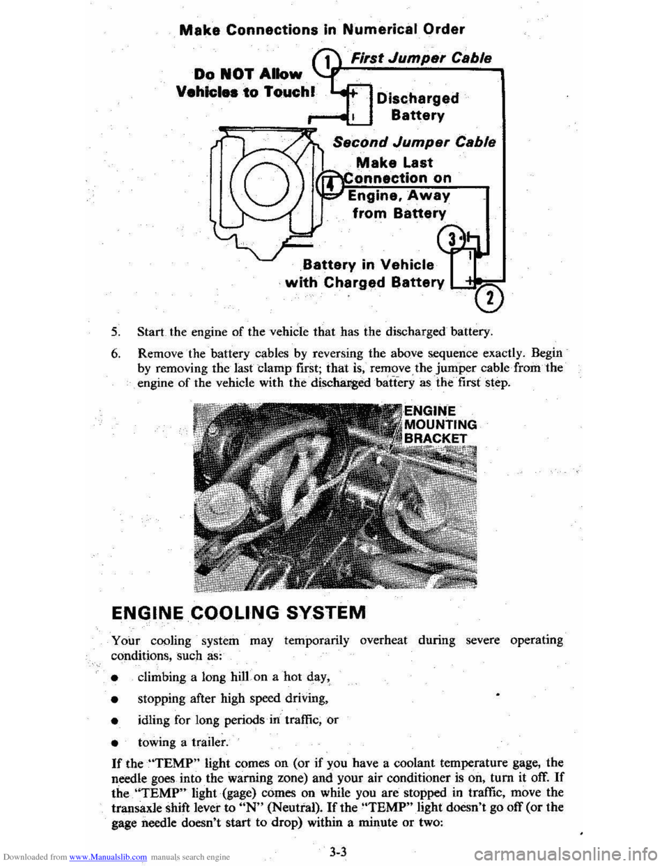
Downloaded from www.Manualslib.com manuals search engine Make Connections In Numerical Order
First Jumper Cable
Discharged
Battery
Make Last
onnectlon on
Engine. Away
from Battery
Battery in Vehicle
with Charged Battery LC"""=-
5. Start the engine of the vehicle that has the discharged battery.
6. Remove the battery cables by reversing the above sequence exactly. Begin
by removing the last clamp first; that is, remove the jumper cable· from the engine of the vehicle with the' discha:r,g:edbatTery as the' first step.
ENGINE COOLING SYSTEM
Your cooling system may temporarily overheat during severe operating
conditions, such as:
• climbing a long hilLon a hot qay,
•
stopping after high speed driving,
• idling for long periods' in' traffic, or
• towing a trailer.
If theUTEMP" light comes on (or if you have a coolant temperature gage, the
needle goes
into the warning zone) and your air conditioner is on, tum it off. If
the. 'ITEMP" light (gage) comes on while you are stopped in traffic, move the
transaxle shift lever to UN" (Neutral). If the "TBMP" light doesn't go off (or the
gage
needle doesn't start to drop) within a minute or two:
3-3
Page 68 of 95
Downloaded from www.Manualslib.com manuals search engine 3. Stop the engine. Open the radiator drain valve to drain the coolant. (Drainage
may be speeded by removing the drain plugs in the block.)
4. Close the drain valve (install block drain plugs, if removed). Add water until
the system is filled and run the engine until the upper radiator hose is hot again.
5. Repeat steps 3 and 4 several times until the drained liquid is nearly colorless.
6. Drain the system and then close the radiator drain valve tightly. (Install block
drain plugs, if removed.)
7. Disconnect all hoses from the coolant recovery tank. Remove the tank and
pour out any fluid. Scrub and clean the inside of the tank with soap and water.
Flush it well with clean water,
then drain it. Reinstall the tank and hoses.
8. Add enough water and ethylene glycol antifreeze (meeting GM Specification
1899-M)to provide the required cooling, freezing, and corrosion protection. Use a solution that is at least 50 percent antifreeze, but no more than 70
percent antifreeze. Fill the radiator to the base of the filler neck and fill the
coolant recovery
tank to the "Full Hot" mark. Put the recovery tank cap back
on.
9. Run the engine, with the radiator cap removed, until the upper radiator hose
is hot.
10. With the engine idling, add coolant to the radiator until it reaches the bottom
of the filler neck. Install the radiator cap, making sure the arrows on the cap line up with the overflow. tube.
It is the owner's responsibility to:
• Maintain cooling system freeze protection at _37°C (_34°F) to ensure
protection against corrosion and loss of coolant from boiling. (A SO/50
mixture of water and ethylene glycol antifreeze will provide freeze protection
to ~ 37°C ore -34°P.) You should do this even if you don't expect freezing
temperatures.
• Add ethylene glycol base antifreeze that meets GM Specification 1899-M
when antifreeze
hasto be added because of coolant loss or for more protection
' against freezing at temperatures lower than _37°C (-·J4°P).
NOTICE: Do not use alcohol or methanol-base antifreeze. or plain water alone. in your vehicle at any time. They will boil at a lower pOint than that at which the hot light indicator (or temperature gage) works. and they do not provide proper protection against corrosion.
Radiator Pressure Cap
The radiator cap, a 105 kPa(15 psi) pressure type, must be installed tightly,
otherwise coolant may be lost and damage to engine may result from overheating.
Radiator pressure caps should be checked periodically for proper operation.
If
replacement is required, an AC cap is recommended.
Thermostat
The engine coolant temperature is controlled by a thermostat. It stops coolant flow
through the radiator until a preset temperature is reached. This thermostat is
installed in
the engine coolant outlet on the engine block. The same thermostat is used in both winter and summer. When a replacement is needed, AC~Delco parts
are recommended.
5-7
Page 86 of 95
Downloaded from www.Manualslib.com manuals search engine FUSES AND CIRCUIT BREAKERS
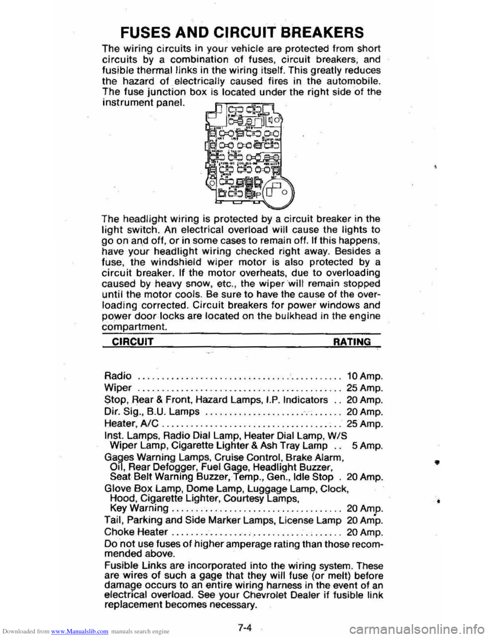
The wiring circuits in your vehicle are protected from short circuits by a combination of fuses, circuit breakers; and fusible thermal links in the wiring itself. This greatly reduces
the hazard of electrically caused fires in the automobile.
The fuse junction box is located under the right side of the instrument panel.
The
headlight wiring is protected by a circuit breaker in the light switch. An electrical overload will cause the lights to go on an,d off, or in some cases to remain off. If this happens , have your headlight wiring checked right away. Besides a fuse, the windshield wiper motor is also protected by a circuit breaker. If the motor overheats, due to overloading caused by heavy snow, etc., the wiper ·will remain stopped until the motor cools. Be sure to have the cause of the over· loading corrected. Circuit breakers for power windows and power door locks are located on the bulkhead in the engine
compartment.
CIRCUIT RATING
Radio ........................................... 10 Amp.
Wiper
......... ......................... ......... 25 Amp .
Stop, .Rear & Front, Hazard Lamps, I.P. Indicators .. 20 Amp.
Dir.
Sig .. B.U. Lamps .............................. 20 Amp.
Heater,
AlC .............. ........................ 25 Amp .
Inst. Lamps, Radio Dial Lamp, Heater Dial Lamp, WIS Wiper Lamp, Cigarette Lighter & Ash Tray Lamp .. 5 Amp.
Gages Warning Lamps, Cruise Control , Brake Alarm,
Oil, Rear Defogger, Fuel Gage, Headlight Buzzer, Seat Belt Warning Buzzer, Temp., Gen., Idle Stop . 20 Amp.
Glove
Box Lamp, Dome Lamp, Luggage Lamp, Clock, Hood, Cigarette Lighter, Courtesy Lamps,
Key Warning .................................... 20 Amp.
Tail, Parking and
Side Marker Lamps, License Lamp 20 Am·p.
Choke Heater . . . . . . . .. .. .. . .. . . . . . . . .. . . . . 20 Amp .
Do
not use fuses of higher amperage rating than those recom· mended above.
Fusible Links are incorporated into the wiring system. These
are wires
of such a gage that they will fuse (or melt) before damage occurs to an entire wiring harness in the event of an electncal overload. See your Chevrolet Dealer if 1usible link replacement becomes necessary.
7-4
•
Page 88 of 95
Downloaded from www.Manualslib.com manuals search engine Air Cleaner ...... . Air Conditioner
Automat ic ............ . Malnt.nance Air Pre •• ur •. Tire .... A ir Vents ..... Alternator (GEN) Light .. Aluminum Car •.. AM or AM·fM R.dios ..... Antifra.z . ..... ......... .......... . App.aranc. Car ...... Ashtrays & l ighters. Assi.tance. Owner .. Autom.tic DOOf lOCks
Autom.tic: Trann.l. Malnt.mimc. Operation .. Operating Tip$ ..... Axl. , Drive .. Sabies, Reatraint of . San Joints S.ttary
5-8
2 -
22 5·10 5·11 2·21 2·17 .-. 2·24 (S •• "Coolant") '-1 2-20 0-1 1-2
5-. ,-a 2 ·10 5-8 1·10 5-8
Em.rgency SIIHting.. 3-1 Fr •• dom .... 5·9 G •• Caution... 3-1 ; GEN Light ... 2·11 T •• t Indicator... 5·9 Befortl Oriylng Your V.hicle ,., Belt •. Seat .... M. (S .. "Seat Baits",
Blower, H.at.r &. Air Cond.... 2-20 Body Oamag... 4·4 Brak.s Adjustment P.dal Trav.l Traller 'Towing .. Warning Light Bre.ka,., Circuit
Break·ln Period, N.w V.hicl •... Bright Headlights .....
2-14 2·14 1 -11 2·17 7-4 2-' 2·7,2·14 4-4 1 -3.7·4 1-12 3-6 {S •• "Sound"l 2·18, 5-2
Bright Metal CI.aning ......... .. Bl,llbs lit Fu ••• Bumpe ... lit Hitch ••.. 81,1mper Jack Operetion Bun.r •.. C·4 Syst.m .. C •• Coolant RaeoV.ry Tenk .. FI,I.I. Powar St •• ring .... R.diator ..... . Cap.city. Cargo W.ight ... .•. Cap3Cme •. Fluid .. C.r Br.ak·ln Period , N.w ..... . C.r Chemic. I ......... .. C.rbon Monoxid. Caution
'-5 Inside Back Cover .-a '-7 6-12 7-1 2-' '-7 '-1 C.r. &. CI.aning, Appear.nce 4-1 C.rgo Capacity. 5-10 Cargo on Roof, C.rrying.. ......... ............... 1·3 CargoR.ck, Roof ..... 2·29 Cargo Coyer .. ................ ........... 2-27 CATALYST Indic.tor..... 2 ·18 C.t.lytic Conv.n.r C ·4 System ......... . Chains, Tir • ..... Ch.nging Whe.'s • Tiras .. Ch.rging Systam Indicator .... CHECK ENGINE light..
2·18,5--2 5·14 3-6 3-2 2-18, 5-2
7-6
Checklist. Driver ....... . Child Seats lit Ra.traint •.. Chrome Protection .. Cigarette lightar .... Circuit Breakars . Citizens Band Radio ... " .... " .... " .. M ••••••• Cleening .. Clock
Cloth Trim Car." .. Clutch Pedal Adjl,lstment.. .. Cold Welther Stlrting ..... Compla int Procedure ..
1-1 1-10 .-. 2·20 7-' 2·2 ~ 4-1 2·20 .-, 5-8 '-a 6-1
Conditionar, Air ....... (See "Air Conditi on.r") Con.umer Relations... 6-1
Cony.)! Mirror ... C ooling System Antifraet. ICoolant, .. Overheating .. Recovary Tank .. S.rvice .. Thermostat .. CorrOSion Protection Countries. Oper.ting in Foraign ..... Cruise Control .. Cu.tomer Sarvice .. Oamage. Sheet M.tal...-. D.fogger. Rear Window. Defro.hlT , Windshiflld .. Oalay Wipers .. Descend .ing a Grade Trail.ring .. Dimen.ion. Dimmer Switch, H.adlight Dipsticks
Engine Oil .. Power Staering .. Diractional Sign." .... . Oi.c Br~ ••.. Door lock ......
Drrve lOOe
1-3
'-5 3-3 5-S '-5 5-7 .-. 2 -3 2·12 6-1 '-5 2-21 2 -20, 2·23 '-7 '-8 1-11 7-1 2-14
'-3 .-a ,-u 2·1S 1-2 5-8 Driver Checklist.... 1·1 Driving Down Steep Gr.de........ 2·9 In Ou.ty Ar......... 5·3 on Slippery Surfaces ....... .......... ,.... 2·9 Ec;Gnomy Tips , Fu" 2·4 Electric-Powered Option...... (See "Power")
Ele<:tricel System 8IttMY ... ... .
Bulbs ...... .
Circuit Brlak.rs. , .... GEN (Glnerator) light ...... Jump Scarting .. .. Sparil Plugs .. Voltm.ter ... Erne:rg.ncy , In Ca •• of Brak. Warning Light Engine Hot light .. Freeing Vahicle When Stuck ... Hazard Warning Fla.h.r .... J.cking ..... Jump 51anlng._. Towing Clr. Emission Caution .................................. . Emi .. ion Control CAT AL YST Indicator
5-S 7-3 7-. 7-' 2·17 3-1
7-2
2·19
2·17 2·17 3-7
3-1
3 ·4 .3·5 3-1
3-7
'-1
2·19
,
Page 90 of 95
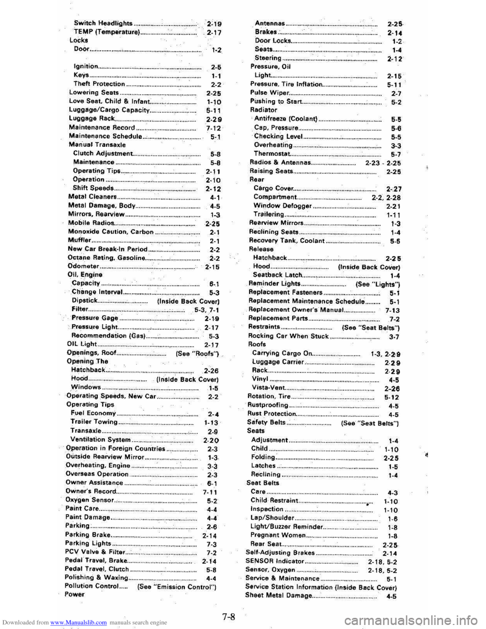
Downloaded from www.Manualslib.com manuals search engine Switch Headlights .... TEMP (Temperature) .. Locks Door ...
2~19 2-17 1-2
Ignition ............................................. .. 2-5 1-1 2-2
2-25 Keys .. Theft Protection .. Lowering Seats .. Love Seat, Child & Infant: .. Lugglige/Cargo Capacity ... Luggage Rack ... Maintenance Record .. Maintenance Schedule .. Manual Transaxle Clutch Adjustment. .. .
1-10 5-11 2·29 7-12 5-.1
Maintenance ........................................... . 5-8
5-8
2-11
2· 10 2-12 4-1 4-5
1-3
Operating Tips .. Operation .. Shift Speeds. Metal Cleaners .. Metal Damage, Body ... Mirrors, Rearview .. Mobile Radios-. Monoxide Caution, Carbon .. . 2-25 2-1
2-1 2-2
2-2
2-15 Muffler ............................................... . New Car Break-In Period Octane Rating, Gasoline ... Odometer Oil, Engine Capacity .. Change Interval.. Dipstick ... Filter ... PreSsure Gage .. Pressure Light... Recommendation (Gas) .. OIL Light.. Openings, Roof... Opening The Hatchback ... Hood .. Windows ..
6-.1 5-3 (inside Back Cover) 5-3,7·1 2·1-9 2-17
5-3
2-17 (See "Roofs")
2·26 (Inside Back Cover) 1-5 Operating Speeds, New Car... 2-2 Operating Tips Fuel Economy.. 2-4 Trailer Towing.. 1-13 Transaxle... 2-9 Ventilation System.. 2.20 Operation in Foreign Countries.. 2"3 Outside Rearview Mirror.. 1.3 Overheating, Engine.. 3-3 Overseas Operation.. 2.3 Owner Assistance.. 6-1 Owner's Record... 7-11 Oxygen Sensor., 5.2 Paint Care.. 4-4
Paint Damage .. Parking;. Parking Brake .. Parking Lights .. PCV Valve & Filter .. Peda'·TI"avel, Brake ... Pedal Travel, Clutch .. Polishing & Waxing .. Pollution Control Power
4-' 2-. 2-14 7-3 7·2 2-14 5~8
.-. (See "Emission Contron
7-8
Antennas Brakes .. Door Locks .... Seats ... Steering Pressure, Oil Light ... Pressure. Tire Inflation ... Pulse Wiper ...
2-25
2-14
1-2 1-' 2·12
2-15
5-11
2-7
Pushing to Start ................................ .. 5-2 Radiator Antifreeze (Coolant) .. Cap, Prassure .. Checking Level .. Overheating .. Thermostat...
Radios & Antennas ... Raising Seats ... Rear Cargo Cover ...................... .. Compartment .. . Window Defogger .. Trailering .. Rearview Mirrors .. Reclining Seats .. Recovery Tank, Coolant .. Release
Hatc.hback
Hood .. Seatback Latch ... Reminder Lights ....
Replacement Fasteners
5-5 5-. 5-5 3-3 5-7
2-23 -2-25
2-25
2-:27
2-2,2-28 2-21 '·11 1-3 1-' 5-5
2-25 (Inside Back Cover)
1-' (See "Lights") 5-1
5-1 Replacement Maintenance Schedule .. Raplacement Owner's·Manual... 7-13 Replacement Parts ............. ....................... 7-2 Restraints .. Rocking Car When Stuck .. Roofs Carrying Cargo On ... Luggage Carrier .. Rack .. Vinyl .. Vista-Vent. ... Rotation, Tire .. Rustproofing .. Rust Protection ... Sefety Belts .. Seats (See
"Seat Belts") 3-7
1-3,2-2,9 2·29 2·29
'-5 2-26 5-12
'-5 '-5 (See "Seat Belts")
Adjustment.. 1-4 Child... 1-10 Folding.. 2-25 Latches..
1-5 Reclining.... . '-4 Seat Belts Care.. 4.3 Child Restraint ............................................ 1.10 Inspection.. 1-10 Lap/Shoulder.. 1-6 Light/Buzzer Reminder... 1;8 Pregn~nt Women .. Rear Seat. ... Self-Adjusting Brakes .. SENSOR Indicator ..
1-8 2-25 2-14 2-18,5-2 Sensor, Oxygen.... 2-18,5-2 Service & Maintenance.. 5-1 Service Station Information (InSide Back Cover) Sheet Metlll Damage... 4-5