fuel cap CHEVROLET CITATION 1980 1.G Owners Manual
[x] Cancel search | Manufacturer: CHEVROLET, Model Year: 1980, Model line: CITATION, Model: CHEVROLET CITATION 1980 1.GPages: 95, PDF Size: 21.48 MB
Page 39 of 95
Downloaded from www.Manualslib.com manuals search engine Clear snow and ice from the rear window to improve the efficiency of the reaT
window defogger.
Air Outlets
The twin barrel vertical type center outlets maybe rotated or vanes turned to direct
air flow in direction desired. The outlets at each end of the instrument panel-may
be rotated or vanes adjusted as desired.
AIR CONDITIONING SYSTEM
This system combines heating and cooling capabilities for comfort in all weather
conditions.
During some air conditioning operation conditions, slight increases and decreases
of engine speed/power may be noticed. This should be considered normal, as the
system
is designed to cycle the compressor -ON and OFF to maintain desired
cooling. The reduced compressor operation should benefit fuel economy.
III
~" HI
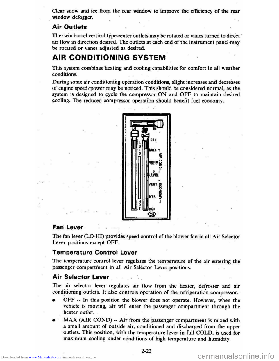
Fan Lever
,
• L •
H • T
O,!
!1~)t 1 ~ ~ ORMS . 2
• I _~v~
VEN.T_~ o ;; HTR ! J
." ®
The fan lever (LO-HI) provides speed control of the blower fan in all Air Selector Lever positions except OFF.
Temperature Control Lever
The temperature control lever regulates the temperature of the air entering the
passenger compartment in an Air Selector Lever _ positions.
Air Selector Lever
The air selector lever regulates air flow from the heater, defroster and air
conditioning outlets.
It also controls operation of the refrigeration compressor.
• OFF --In this position the blower does not operate. However, when the
vehicle is moving, air will enter the passenger compartment through the
heater outlet.
• MAX (AIR COND) --Air from the passenger compartment is mixed with
a small amount
of outside air, conditioned and discharged from the upper
outlets. This position, with the temperature lever in full
COLD, is used for
maximum cooling under conditions
of high temperature and humidity.
2-22
Page 62 of 95
Downloaded from www.Manualslib.com manuals search engine Section 5
SERVICE AND MAINTENANCE
CAUTION: As with any machine, take care when making any check, doing any maintenance. or making any repair. t6ayoid being injured. Note that some of the materials in this vehicle may be hazardous if used, serviced, or handled improperly. Improper or incomplete serVice could also lead to the vehicle itself not working properly which may result in personal injury, or damage to the vehicle or its equipment. If you have any question about carrying out some service, have the service done by 8 skilled mechanic.
REPLACEMENT FASTENERS
During car maintenance, any fasteners used to replace older ones must have the
same measurements and strength as those removed, whether metric or customary. (The numbers on the heads of metric bolts and on the surfaces of metric nuts show
their strength. Customary bolts use radial lines to show this, while most customary
nuts
do not have strength markings.) Fasteners taken from the car should be saved
for re-use in the same spot when possible. Where a fastener cannot be used again,
take care to choose a replacement that matches the old one.
For information and help, see your Chevrolet dealer.
CAUTION: This vehicle is primarily dimensioned in the metric system, Most fasteners are i'neti'icand many lire vary closein dimension to well-known customary fasteners in the inch system. Mismatched or incorrect fasteners can result in damage to the car or possibly personal injury.
MAINTENANCE SCHEDULE
For owner convenience , a separate folder has been provided with your vehicle
which contains a complete maintenance schedule. It also briefly describes the
safety, emission control, lubrication and general service your vehicle requires.
The Maintenance Schedule folder is supplemented by this section of the Owner's
Manual, as well as a Warranty Information folder also furnished with your vehicle.
Read all three publications for a full understanding
of your vehicle's maintenance
needs.
You can get a replacement Maintenance Schedule from your dealer or send the VIN(or serial) number of your vehicle to Consumer Relations, Chevrolet Central
Office, Chevrolet Motor Division, Detroit, Michigan 48202.
Fuel Cap
The fuel tank filler cap has a "screw-on ratcheting type" feature. To·remove:
•
Rotate cap counterclockwise to clear the inside of the filler neck. This
will allow any residual pressure
to escape.
• To install, reverse this procedure and tighten cap securely until a "ratcheting", clicking sound is heard indicating cap is on properly.
NOTICE: If you need to replace the fuel cap, use only a cap with these same features as specified for your model. An incorrect fuel cap can result in a serious malfunction of the fuel system or emission control system. You can get a correct replacement cap from your dealer.
5-1
Page 66 of 95
Downloaded from www.Manualslib.com manuals search engine NOTICE: You cannot read the correct fluid level if you have just driven the car for a long time at high speed, in city traffic in hot weather, or if the car has been pulling a trailer. Wait. until the fluid has cooled down (about 30 minutes).
Remove the dipstick located on the driver's side forward of the cowl. Carefully
touch the wet end of the dipstick to find out if the fluid is cool, warm or hot. Wipe
it clean and push it back in until the cap seats. Pull
out the dipstick and read the
fluid level.
• If it felt cool or warm (about room temperature), the level should be
between the dimples above the "Full" mark.
• If it was too hot to hold. the level should be at or in the hatched area.
Add just enough DEXRON-®n fluid to fill the transaxle. It takes only 0.5 liter
(one pint)to raise the level from "Add" to "Full" with a hot transaxle.
Do not overfill the transaxle. Overfilling can cause foaming and loss of fluid, which
could result in transaxle damage.
Automatic Transaxle Drain Intervals
Change the transmission fluid and change the filter (or clean the screen) as
outlined in Section
A of the Maintenance Schedule folder.
ELECTRIC FAN
CAUTION: Keep hands, tools, and clothing away from the angine cooling fan to help prevent personal injury. This fan is electric and can come on whether or not the engine is running. The fan can start automatically in response to a heat sensor when the ignition is in the "Run" position.
ENGINE COOLING SYSTEM
The coolant recovery system is standard. The coolant in the radiator expands with
heat, and the overflow collects in the recovery tank. When the system cools down,
the coolant
is drawn back into the radiator.
The cooling system was filled at the factory with a quality coolant that meets
GM Specification 1899-M. The cooling system is designed to use coolant (a mixture
of water and ethylene glycol antifreeze) rather than plain water. The coolant
solution should be used year round. It has many advantages, such as:
• provides freezing protection down to _37°C, (-34°P)
•
provides boiling protection up to 128QC, (262°P)
•
protects against rust and corrosion in the cooling system,
• maintains the proper engine temperature for efficient operation and emission
control, and
• allows proper operation of the coolant temperature light (or gage).
See Section A of the Maintenance Schedule folder to find out when the coolant
must
be replaced.
COOLING SYSTEM CARE
Check the cooling system at regular intervals, such as during fuel stops. You
usually do not need to remove the radiator cap to check the coolant level. Lift
the engine hood and look at the "see through" coolant recovery tank. When the
engine
is cold, the coolant level -should be at or slightly above the "Full Cold"
mark on the tank. When the engine has fully warmed up, the level should be at ')r slightly below the "Full Hot" mark on the tank. If the coolant level is low,
5-5
Page 72 of 95
Downloaded from www.Manualslib.com manuals search engine LUGGAGE/CARGO LOAO CAPACITY
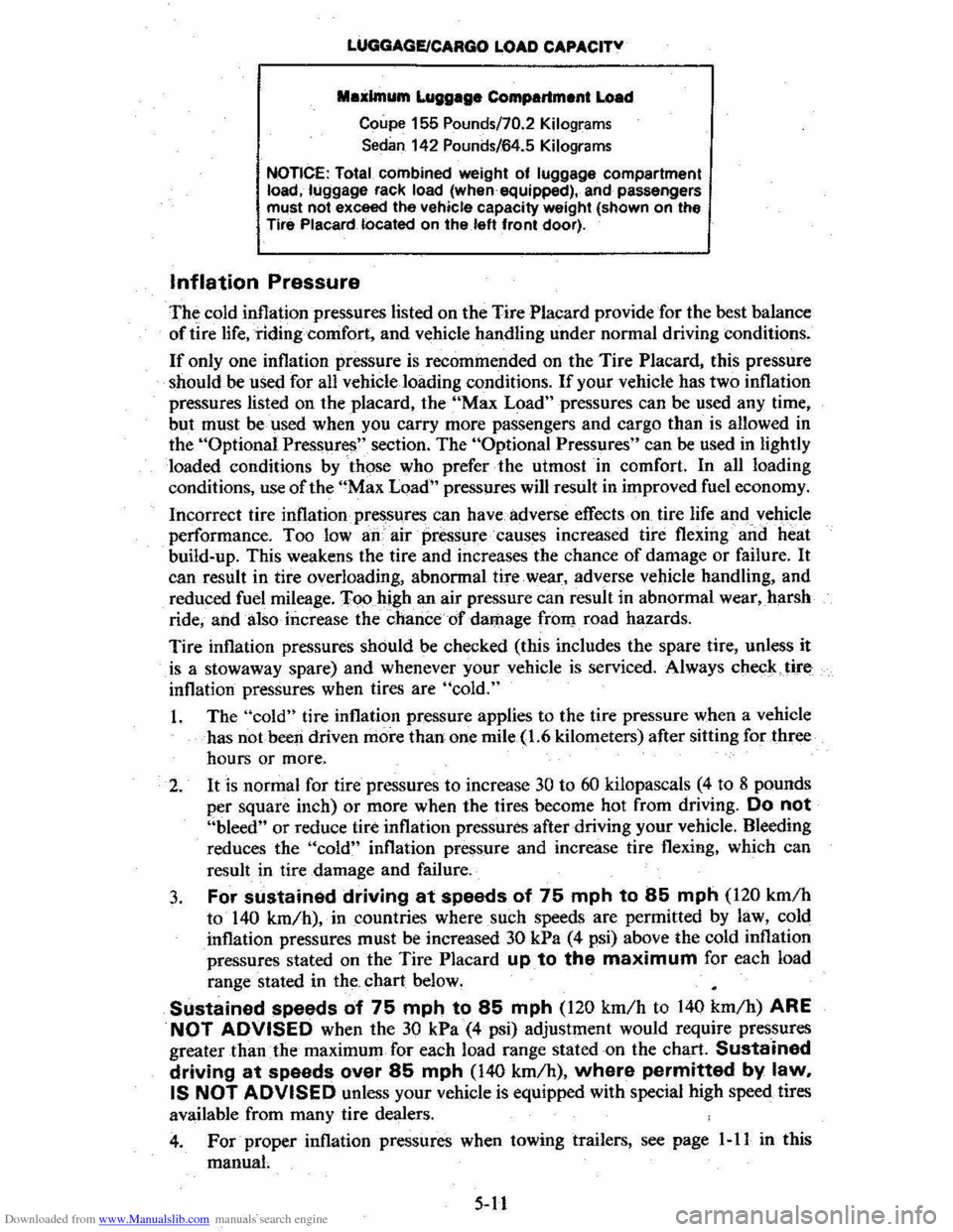
Maximum Luggage Compartment Load
Coupe 155 Pounds/70.2 Kilograms
Sedan 142 Pounds/64.5 Kilograms
NOTICE: Total combined weight of luggage compartment
load, luggage rack load (when-equipped) •. and passengers must not exceed the vehicle capacity weight (shown on the Tire Placard lOcated on the.left front door).
Inflation Pressure
The: cold inflation pressures listed on the Tire Placard provide for the best balance
of tire life, riding comfort. and vehicle handling under normal driving conditions.
If only one inflation pressure is recommended on the Tire Placard, this pressure
should be used for aU vehicle loading conditions. If your vehicle has two inflation
pressures listed on the placard, the "Max LDad" pressures can be used any time,
but must be used when you carry more passengers and cargo than is allowed in
the "Optional Pressures" section. The "Optional Pressures" can be used in lightly
loaded conditions by
'those who prefer the utmost in comfort. In all loading
conditions, use of the "Max Load" pressures will result in improved fuel economy.
Incorrect tire inflation pressures
can have adverse effects on tire life and_vehicle performance. Too Iowan" air pressure·"causes increased tire flexing and heat
build-up. This weakens the tire and increases the chance of damage or failure. It
can result in tire overloading, abnormal tire wear, adverse vehicle handling, and
reduced fuel mileage. 'I'oohigh
an air pressure can result in abnormal wear, harsh
ride, and also increase the chance of dar:nage from road hazards.
Tire inflation pressures should be checked (this includes the spare tire, unless it
is a stowaway spare) and whenever your vehicle is serviced. Always checJ<.,tire
inflation pressures when tires are "cold."
1. The "cold" tire inflation pressure applies to the tire pressure when a vehicle
has
not· been driven more than-one mile (1.6 kilometers) after sitting for three
hours or more.
2. It is normal for tire pressures to increase 30 to 60 kilopascals (4 to 8 pounds
per square inch)
or more when the tires become hot from driving. Do not "bleed" or reduce tire inflation pressures after driving your vehicle. Bleeding
reduces the
"cold" inflation pressure and increase tire flexing, which can
result in tire damage and failure.
3. FOr sustained driving at speeds of 75 mph to 85 mph (120 km/h to 140 km/h),in countries where such speeds are permitted by law, cold
inflation pressures must be increased
30 kPa (4 psi) above the cold inflation
pressures stated on the Tire Placard up to the maximum for each load
range stated in
the_ chart below.
Sustained speeds of 75 mph to 85 mph (120 km/h to 140 km/h) ARE
NOT ADVISED when the 30 kPa (4 psi) adjustment would require pressures greater than the maximum for each load range stated on the chart. Sustained
driving at speeds over 85 mph (140 km/h), where permitted by law. IS NOT ADVISED unless your vehicle is equipped with special high speed tires
available from many tire dealers.
4. Forproper inflation pressures when towing trailers, see page 1-11 in this
manuat
5-11
Page 90 of 95
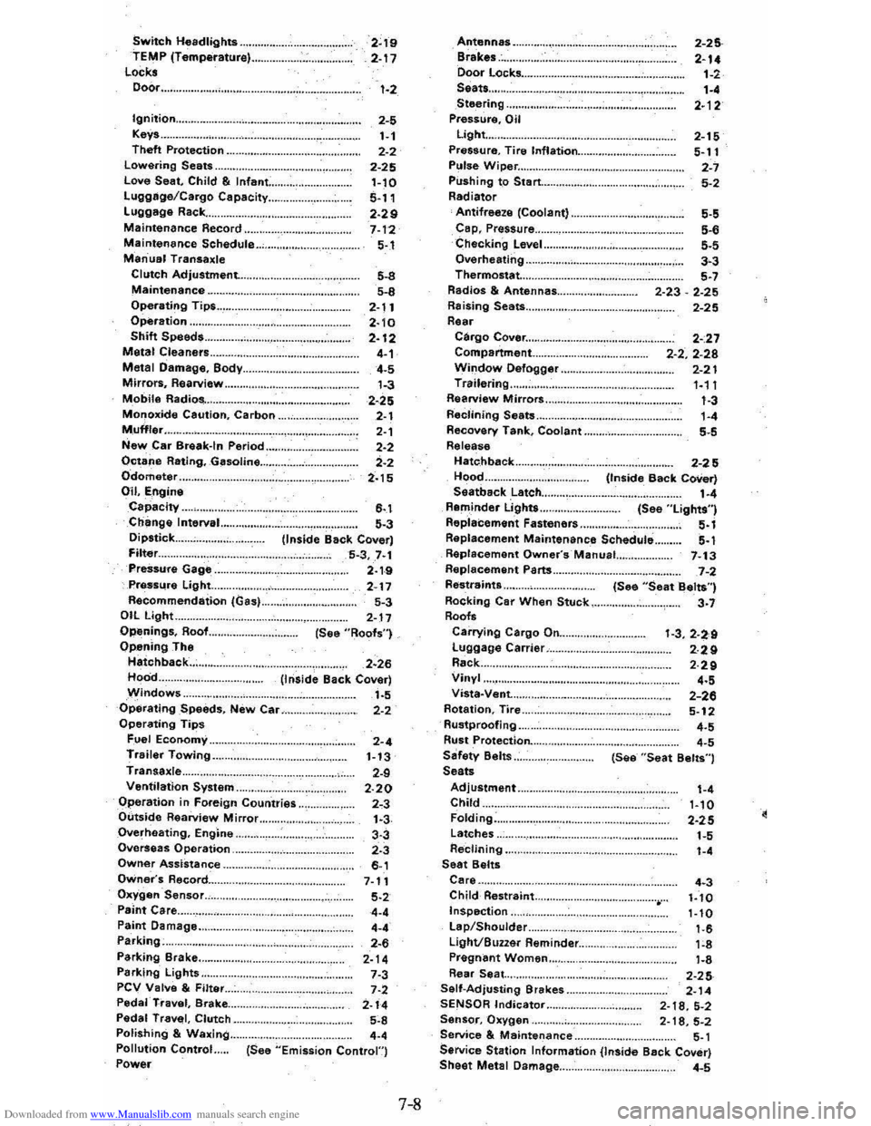
Downloaded from www.Manualslib.com manuals search engine Switch Headlights .... TEMP (Temperature) .. Locks Door ...
2~19 2-17 1-2
Ignition ............................................. .. 2-5 1-1 2-2
2-25 Keys .. Theft Protection .. Lowering Seats .. Love Seat, Child & Infant: .. Lugglige/Cargo Capacity ... Luggage Rack ... Maintenance Record .. Maintenance Schedule .. Manual Transaxle Clutch Adjustment. .. .
1-10 5-11 2·29 7-12 5-.1
Maintenance ........................................... . 5-8
5-8
2-11
2· 10 2-12 4-1 4-5
1-3
Operating Tips .. Operation .. Shift Speeds. Metal Cleaners .. Metal Damage, Body ... Mirrors, Rearview .. Mobile Radios-. Monoxide Caution, Carbon .. . 2-25 2-1
2-1 2-2
2-2
2-15 Muffler ............................................... . New Car Break-In Period Octane Rating, Gasoline ... Odometer Oil, Engine Capacity .. Change Interval.. Dipstick ... Filter ... PreSsure Gage .. Pressure Light... Recommendation (Gas) .. OIL Light.. Openings, Roof... Opening The Hatchback ... Hood .. Windows ..
6-.1 5-3 (inside Back Cover) 5-3,7·1 2·1-9 2-17
5-3
2-17 (See "Roofs")
2·26 (Inside Back Cover) 1-5 Operating Speeds, New Car... 2-2 Operating Tips Fuel Economy.. 2-4 Trailer Towing.. 1-13 Transaxle... 2-9 Ventilation System.. 2.20 Operation in Foreign Countries.. 2"3 Outside Rearview Mirror.. 1.3 Overheating, Engine.. 3-3 Overseas Operation.. 2.3 Owner Assistance.. 6-1 Owner's Record... 7-11 Oxygen Sensor., 5.2 Paint Care.. 4-4
Paint Damage .. Parking;. Parking Brake .. Parking Lights .. PCV Valve & Filter .. Peda'·TI"avel, Brake ... Pedal Travel, Clutch .. Polishing & Waxing .. Pollution Control Power
4-' 2-. 2-14 7-3 7·2 2-14 5~8
.-. (See "Emission Contron
7-8
Antennas Brakes .. Door Locks .... Seats ... Steering Pressure, Oil Light ... Pressure. Tire Inflation ... Pulse Wiper ...
2-25
2-14
1-2 1-' 2·12
2-15
5-11
2-7
Pushing to Start ................................ .. 5-2 Radiator Antifreeze (Coolant) .. Cap, Prassure .. Checking Level .. Overheating .. Thermostat...
Radios & Antennas ... Raising Seats ... Rear Cargo Cover ...................... .. Compartment .. . Window Defogger .. Trailering .. Rearview Mirrors .. Reclining Seats .. Recovery Tank, Coolant .. Release
Hatc.hback
Hood .. Seatback Latch ... Reminder Lights ....
Replacement Fasteners
5-5 5-. 5-5 3-3 5-7
2-23 -2-25
2-25
2-:27
2-2,2-28 2-21 '·11 1-3 1-' 5-5
2-25 (Inside Back Cover)
1-' (See "Lights") 5-1
5-1 Replacement Maintenance Schedule .. Raplacement Owner's·Manual... 7-13 Replacement Parts ............. ....................... 7-2 Restraints .. Rocking Car When Stuck .. Roofs Carrying Cargo On ... Luggage Carrier .. Rack .. Vinyl .. Vista-Vent. ... Rotation, Tire .. Rustproofing .. Rust Protection ... Sefety Belts .. Seats (See
"Seat Belts") 3-7
1-3,2-2,9 2·29 2·29
'-5 2-26 5-12
'-5 '-5 (See "Seat Belts")
Adjustment.. 1-4 Child... 1-10 Folding.. 2-25 Latches..
1-5 Reclining.... . '-4 Seat Belts Care.. 4.3 Child Restraint ............................................ 1.10 Inspection.. 1-10 Lap/Shoulder.. 1-6 Light/Buzzer Reminder... 1;8 Pregn~nt Women .. Rear Seat. ... Self-Adjusting Brakes .. SENSOR Indicator ..
1-8 2-25 2-14 2-18,5-2 Sensor, Oxygen.... 2-18,5-2 Service & Maintenance.. 5-1 Service Station Information (InSide Back Cover) Sheet Metlll Damage... 4-5
Page 95 of 95
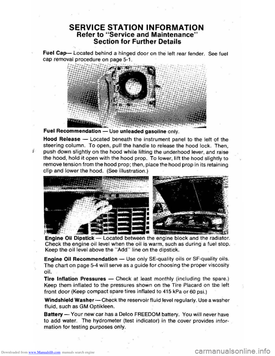
Downloaded from www.Manualslib.com manuals search engine SERVICE STATION INFORMATION
Refer to "Service and Maintenance"
Section for Further Details
Fuel Cap-Located behind a hinged door on the lett rear fender. See fuel cap removal procedure on page 5-1.
Fuel Recommendation -Use unle~ded gasoline only .
Hood Release -Located beneath the instrument panel to the left of the
steering column. To open, pull the handle to re lease the hood lock . Then ,
j" push down slightly o "n the hood whil e lifting the underhood lever, and raise
the hood, hold it open with the hood prop. To lower, lift the hood slightly to
remove tension from the hood
prop; then , place the hood prop in its retainin g
clip and lower the hood. (See illustration.)
Engine Oil -located between the engine block and the radiator. Check the engine oil level when the oil is warm, such as during a fuel stop. Keep the oil level above the "Add" line on the .dipstick.
Engine Oil Re "commendatlon -Use only SE-q ualit y oils or SF-quality oils .
The chart o n page 5-4 will serve as a gu ide tor choosing the proper viscosity oil. .
Tire Inflation Pressures -Check at least monthly (including the spare .)
Keep them
inflated to the pressures shown on the Tire Placard on the left
front door (Keep compact spare tires inflated to 4t5 kPa or 60 psi.)
Windshield Washer-Check the reservoir fluid level regularly . Use a wa sher
fluid, such as GM Optikleen.
Battery -Your new car has a Delco FREEDOM battery. You will never have
to add water. The hydrometer (test indicator) in the cover provides infor
mation for testing purposes only.