instrument panel CHEVROLET CITATION 1980 1.G Owners Manual
[x] Cancel search | Manufacturer: CHEVROLET, Model Year: 1980, Model line: CITATION, Model: CHEVROLET CITATION 1980 1.GPages: 95, PDF Size: 21.48 MB
Page 4 of 95
Downloaded from www.Manualslib.com manuals search engine 1980 CHEVROLET CITATION
OWNER'S
MANUAL
rHIS "lANUAL SHOULDSE CONSIDERED A PERMANENT PART OF THIS CAR. IT 3HOULD STAY WITH THE CAR WHEN SOLD. TO PROVIDE THE NEXT OWNER WITH "lPORTANT OPERATING. SAFETY. AND MAINTENANCE INFORMATION.
CHEVROLET MOTOR DIVISION
GENERAL MOTORS CORPORATION
DETROIT, MICHIGAN 48202
4lrinformatlon, illustrations and specifications in thisma'n 'ual are ' based on the latest t. )roduct information available at the time of printing. The right is rese rved to make ~hanges at any time without notice.
Co" cars sold in Canada , substitute the name General Motors of Canada Limited ",herever the name Chevro-'et Motor D;vision appears in this manual.
Table of Contents
Section
.1 Before Driving Your · Citation .... . ,-,
-__ 2 Starting and Operating .. . ..... 2-'
Steering Column Contr~!s 2-5
.
Floor Controls .. 2-13
Instrument Panel 2-15
Other Controls and Features . 2-26
3--'ln Case of Emergency . 3-1
4 Appearance Care .. ..... 4-'
:' 5 Service and Maintenance 5-'
6 Owner Assistance. 6-1
7 Specifications, service Manuals , Ind ex, Service Station Information .... ". _ .... , ................... 7~ 1
Page 19 of 95
Downloaded from www.Manualslib.com manuals search engine • Adjust the heating or cooling system to force outside air into the car as . d esc ribed abo ve bUI set the fan to high speed .
• On cars with outside air vents in or under the instrument panel, open the vents fully.
New. Car "Break-In" Period
You can drive your new car from its very first mile/kilometer without following .
a
formal"break~in" schedule. However, there'are things you can do during the
fir st few hundred miles/kilometers of driving that will add to the future
perf orm ance and econ omy of your car.
We recommend you limit your speed during the first 500 miles (800 kiJomet ers) ~
to a maximum of 55 mph (90 km/h) ; but do not drive for long period s al any'
one constant speed, either Jast
or slow. During this time , avoid fulllhronJe start s _ and, if possible, avoid h"ard stops especially during the first 200 miles (320
kilometers) of driving.
Always drive at moderate speed until the engine has completely warmed
up.
If yo u plan to use your new car for trailer towing, see additional information in Section 1 under "Trailer Towing."
GUARD AGAINST THEFT
Your new Citation has many features to help prevent theft of the car itself, its
equ ipment, and its content s. But these ami-theft features depend upon you to
work .
THE TIME TO BE MOST ON GUARD IS WHEN LEAVING THE CAR ...
• PARK IN A LIGHTED SPOT WHEN YOU CAN.
• LOCK THE STEERING COLUMN AND TAKE THE KEYS,
•
Turn the key to "Lock," and remove the key. This locks the igniti on and
both steering and shift connols unless your car has a manual transaxle.
In that case, the shift control- is not locked .
• If you must leave a key with the car, leave the square-head key .only .
Take the oval-Read key with you. This will help prevent unwanted entry into your car at a later date, or into your -trunk.
•
FULLY CLOSE ALL WINDOWS AND ANY ROOF PANELS. AND LOCK ALL DOORS.
•
KEEP COSTLY ITEMS OUT OF SIGHT AND LOCKED UP,
•
Never leave things of value in plain sight on seats or noor.
• The glove box offers a place -to hide small items.
• Lock larger items in the trunk or place them in the rear storage .
FUEL REQUIREMENTS
Your engine is designed to use only unleaded gasoline. Unleaded gasoline must
be' used for the emission control $ystem to operate properly. Its use will also reduce
s park plug fouling , -exhaust system corrosion and engine oil deterionition .
Using leaded gasoline can damage the emiS5ion control system and could result
in loss of warranty coverage. This is especially true on cars that have the C-4
System . Leaded gasoline will damage tbe oxygen sensor, which may affect
emission control, fuel economy
and drivabiJity . See "C-4 (Computer Controlled
Catalytic Converter) System" in "Service and Maintenance" Section 5 of this
manual for more information.
2-2
Page 24 of 95
Downloaded from www.Manualslib.com manuals search engine TURN SIGNAL
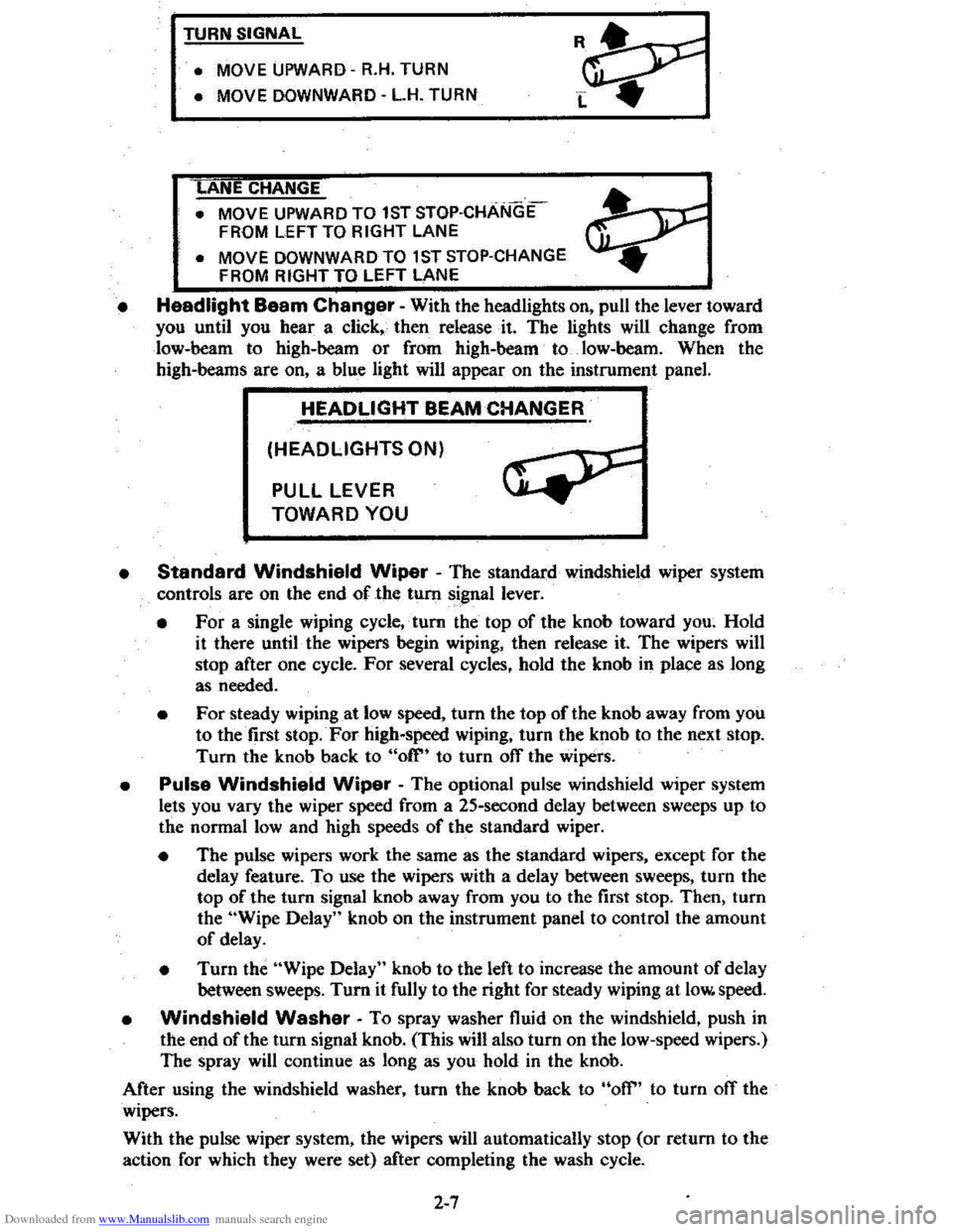
• MOVE
UPWARD -R.H. TURN
• MOVE DOWNWARD -L.H. TURN
ANE CHANGE
• MOVE UPWARD TO 1ST STOP·CHANGE
FROM LEFT TO RIGHT LANE
• MOVE DOWNWARD TO 1 ST STOP-CHANGE
FROM RIGHT TO LEFT LANE
• Headlight Baam Changer -With the headlights on, pull the lever toward you until you hear a click" then release· it. The lights will change from
low-beam to high-beam
or from high-beam to. low-heam. When the high-beams are on, a blue light will appear on the instrument panel.
HEADLIGHT BEAM CHANGER
(HEADLIGHTS ON)
PULL LEVER
TOWARD YOU
•
Standard Windshield Wiper - The standard windshield wiper system
controls are on the end of the tum signal lever.
• For a single wiping cycle,' tum the top of the knob toward you~ Hold
it there until· the wipers begin wiping, then release it. The wipers will stop after one cycle. For several cycles, hold the knob in place as long
as needed.
• For steady wiping at low speed, tum the top of the knob away from you to the first stop. For high-speed wiping, turn the knob to the next stop.
Turn the knob back to "ofr' to turn off the wipers.
• Pulse Windshield Wiper -The optional pulse windshield wiper system
lets you vary the wiper speed from a 25-second delay between sweeps up to
the normal
low and high speeds of the standard wiper.
• The pulse wipers work the same as the standard wipers, except for the
delay feature. To use the wipers with a delay between sweeps, turn the
top of the turn signal knob away from you to the first stop. Then, turn
the "Wipe Delay" knob on the instrument panel to control the amount
of delay.
• Turn the "Wipe Delay" knob to the left to increase the amount of delay
between sweeps. Tum it fully to the right for steady wiping at low. speed.
• Windshield Washer -To spray washer fluid on the windshield, push in the end of the tum signal knob. (This will also turn on the low-speed wipers.)
The spray will continue as long as you hold
in the knob.
After using the windshield washer, turn the knob back to
"off" to turn ofT the
wipers.
With the pulse wiper system, the wipers
will automatically stop (or return to the
action for which they were set) after completing the wash cycle.
2-7
Page 31 of 95
Downloaded from www.Manualslib.com manuals search engine CAUTION: Driving thr~gh water deep enough to wet the brakes may cause the brakes not to work as well. As 8 result the vehicle will not slow down at the usual
rate ; and it may pull to the right or left. After checking to the rear for other vehicle., apply the brakes lightly to check whether this has happened. To dry them quickly, lightly apply the brakes. At the-same time, k .. p a safe forward speed, with plenty of clear space ahead, to the rear, and to the side •. 00 this until the brakes return to normal.
The brake system warning light is covered in the "Instrument Panel" section.
Power Brakes
• If optional power assis t is lost because of a stalled engine or other reasons .
the brakes can normally still be applied with power assist at leas t two times
u sing reserv e power.
• Th e system is designed to bring the vehicle to a full stop on reserve power if the brake pedal is applied once and held down . However . the reserve power
is partly used up each time the brake pedal is applied and rele ased. Do not
pump the brakes when ,brake power assist has been lost, except when needed
to maintain steering control on slippery surfaces.
• Without power assist, the vehicle can still be stopped by pushing much harder
o n the brake pedal. However, the stopping distance may be longer. even
though the brakes themselves remain fully operational.
Self-Adjusting Brakes
• The brakes on this vehicle (exc,ept for the parking brake) are self-adjusting.
They have been design ed so
that periodic brake adjustment is not required.
• The drum brakes adjust themselves when the brakes are firml y applied while
the vehicle is moving backwards.
• The disc brakes adjust themselve s each time the brakes are used.
• If the brak e pedal goes down farther than nonnal. it may be due to a lack
of adjustment. To find out if this is the case, drive backward and forward
a few times , applying the brakes firmly when going each way.
• See yo ur dealer if pedal height does not return to normal, or if there is a rapid
increase in pedal travel, which could be a sign of other brake trouble .
• Also see your dealer if the parking brake needs adjustment' .
NOTICE: "Riding the brake" by resting your foot on the brake pedal when not intending to brake can cause overheated brakes. This can waar out the brake linings faster and damage the brakas thamselvas, 85 well 8S waste fuel.
DIMMER SWITCH
The dimmer switch that controls the headlight high/lo w beam is built into the
turn signal control. See the "Steering Column Controls" Section 2 of this manual.
PARKING BRAKE
• To set the parking brake, fully depress the foot pedal at the far left side.
• For better holding power, first press down the regular brake pedal with your
right foot. Then hold it while setting the parking brake with your lefl foo[.
•
To release the parking brake, pull the "Brake Release" handle located at the
lower left of the instrument panel.
• To help remind you. the brake system warning light is designed to come on if the parking brake control is not fully released and the ignition key is on.
2-14
Page 32 of 95
Downloaded from www.Manualslib.com manuals search engine • Never drive-the vehicle _with the parking brake set as this -may overheat the
reaf brakes reducing their effectiveness and causing excessive wear or damage,
DISC BRAKE WEAR INDICATORS
Front disc brakes have built-in wear indicators that are designed to make a
high-pitched
squealing or cricket-like warning sound when the brake linings are
worn 10 where -new linings are needed. The sound will come and go, or be heard
all the time
when the wheels are rolling, and when the brake pedal is pu~hed down
firmly . Expensive damage can result
if linings are not replaced when needed.
See also the brake checks listed in the Maintenance Schedule folder.
CLUTCH .PEDAL
On models equiPPed with a manual transaxle, a clutch pedal is used to engage
or disengage the clutch, thereby connecting
or disconnecting the engine from the
transaxle and drive1ine to the front wheels. -When the pedal is fully extended the
clutch
is engaged, driving the transaxle arid the front wheels.
INSTRUMENT PANEL P.ND CONTROLS
INSTRUMENTS
The instruments, gages and indicator lights conveniently grouped in the
instrument cluster are des igned to
tell you at a glance many important things about
_the perfonnance of your vehicle _, _ The following information will enable you to
more quickly -understand and properly it';:rerpretthese instruments.
Speedometer
The speedometer chand ·indicatt:5 vehicle speed in miles per hour and kilometers
per hour.
Odometer
The group of six figures . in the speedometer lower center section indicates the
accumulated mileage.
Fuel Gage
The fuel gagewiH register the_APPROXIMATE fuel level in the tank, when the
ignition
is in the RUN position.
When the gage registers
EMPTY, some fuel is still available as a reserve. When
the gage registers
FULL. some additional" fuel can"still be added to the tank. The
following conditiqns may be considered normal:
• Gas station _pump may shut off before fuel gage indicates FULL. •
•
Amount of gasoline required for fill-up may not exactly correspond to gage.
• Needle may not move away from FULL until some time after fill·up.
• Needle may !Dove during turns. stops and-accelerations.
When the ignition switch
is turned to the OFF position, the needle will not
necessarily
retiJrn · all the way to the EMPTY mark.
2-15
Page 38 of 95
Downloaded from www.Manualslib.com manuals search engine lower Air Vents
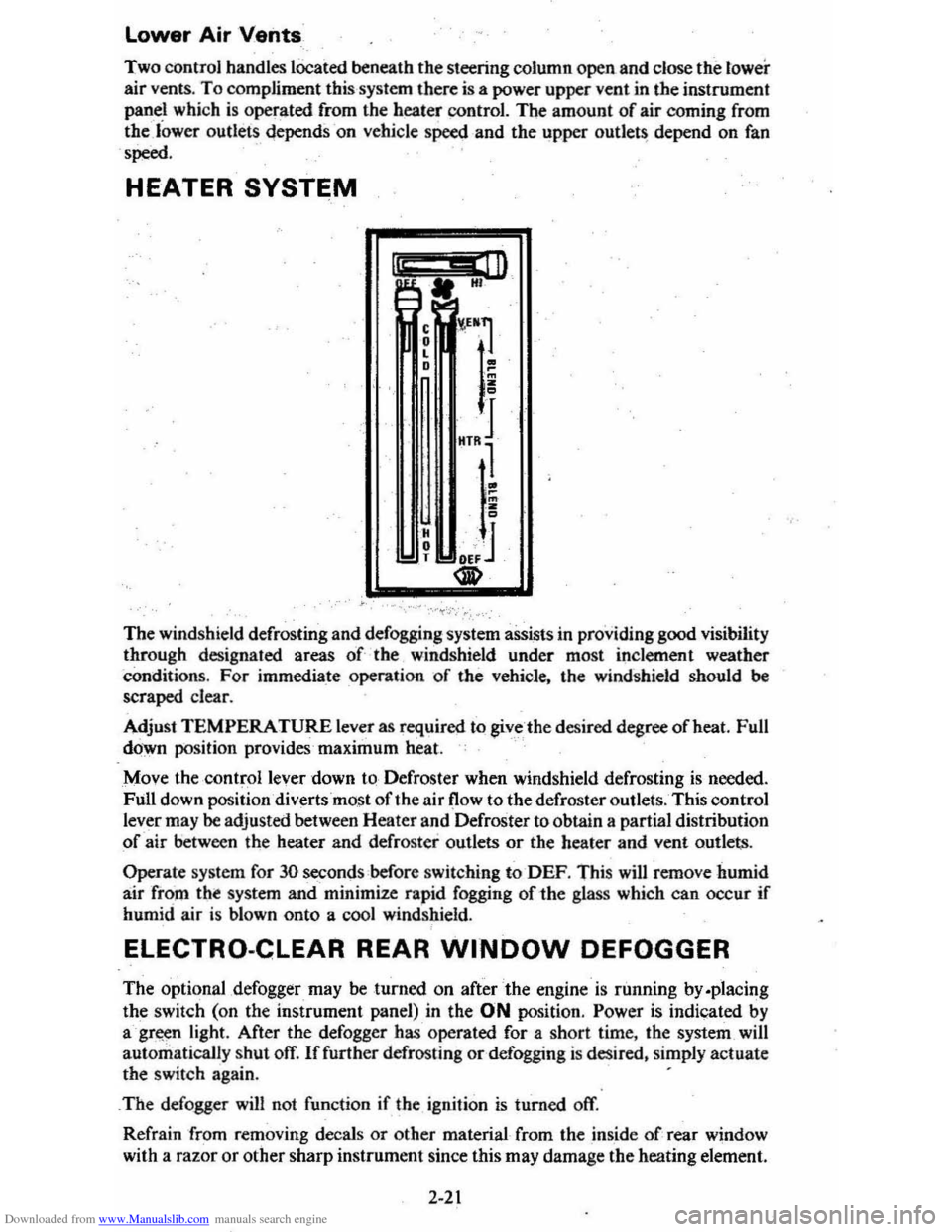
Two control handles lOCated beneath the steering column open and close the tower
air vents. To compliment this system there is a power upper vent in the instrument
panel which is operated from the heater
control. The amount of air coming from the lower cutlets ~epends -on vehicle speed and the upper outJet~ depend on fan
'poed.
HEATER SYSTEM
I" .. ill A. HI
The windshield defrosting and defogging system assists in providing good visibility through designated areas of the windshield under most inclement weather
Conditions. For immedia_te operation of the vehicle. the windshield should be scraped clear.
Adjust
TEMPERATURE lever as required to giv_c -the desired degree afheat. Full
down position provides'maximum heat.
Move the ·
controllever down to-Defroster when windshield defrosting is needed.
Full down position diverts most of the air (low to the defroster outlets. This control
lever may
be adjusted between Heater and Defroster to obtain a partial distribution
of air between the heater and defroster outlets or the heater and vent outlets.
Operate system for 30 seconds before switching to-DEF. This will remove humid
air from tht system and minimize rapid fogging of-the glass which can occur if humid air is blown onto a cool windshield.
ELECTRO-CLEAR REAR WINDOW DEFOGGER
The optional ,defogger may be turned on after the engine is running by.placing
the switch (on the instrument panel) in the ON position. Power is indicated by
agr~n light. After the defogger has operated for a short time. the system _will
automatically
shut ofT. If further defrosting or defogging is desired. simply actuate the switch again. .
_
The defogger will not function if the ignition is turned off.
Refrain from removing decals
or other material from the inside of rear window
with a
razor or other sharp instrument since this may damage the heating element.
2-21
Page 39 of 95
Downloaded from www.Manualslib.com manuals search engine Clear snow and ice from the rear window to improve the efficiency of the reaT
window defogger.
Air Outlets
The twin barrel vertical type center outlets maybe rotated or vanes turned to direct
air flow in direction desired. The outlets at each end of the instrument panel-may
be rotated or vanes adjusted as desired.
AIR CONDITIONING SYSTEM
This system combines heating and cooling capabilities for comfort in all weather
conditions.
During some air conditioning operation conditions, slight increases and decreases
of engine speed/power may be noticed. This should be considered normal, as the
system
is designed to cycle the compressor -ON and OFF to maintain desired
cooling. The reduced compressor operation should benefit fuel economy.
III
~" HI
Fan Lever
,
• L •
H • T
O,!
!1~)t 1 ~ ~ ORMS . 2
• I _~v~
VEN.T_~ o ;; HTR ! J
." ®
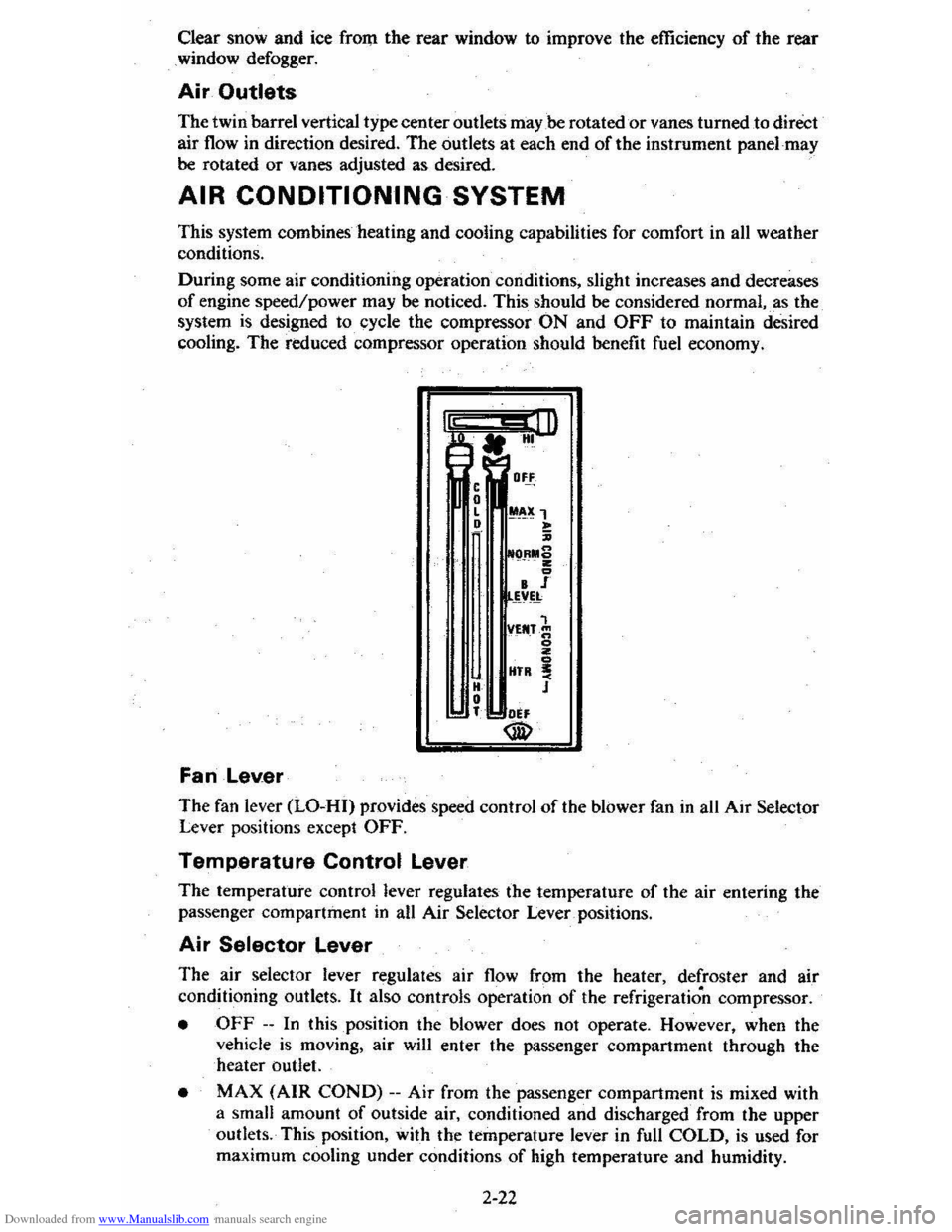
The fan lever (LO-HI) provides speed control of the blower fan in all Air Selector Lever positions except OFF.
Temperature Control Lever
The temperature control lever regulates the temperature of the air entering the
passenger compartment in an Air Selector Lever _ positions.
Air Selector Lever
The air selector lever regulates air flow from the heater, defroster and air
conditioning outlets.
It also controls operation of the refrigeration compressor.
• OFF --In this position the blower does not operate. However, when the
vehicle is moving, air will enter the passenger compartment through the
heater outlet.
• MAX (AIR COND) --Air from the passenger compartment is mixed with
a small amount
of outside air, conditioned and discharged from the upper
outlets. This position, with the temperature lever in full
COLD, is used for
maximum cooling under conditions
of high temperature and humidity.
2-22
Page 40 of 95
Downloaded from www.Manualslib.com manuals search engine • NORM (AIR COND) --Outside aids conditioned as it passes through the
system and is discharged from the upper outlets. This position is used for most
air conditioning situations.
• BI-LEVEL (AIR COND) --Outside air is conditioned and directed out the
upper outlets PLUS the heater outlet. A small amount of air also flows from
the defroster outlets. This position provides comfort
and keeps the windshield
clear under low fogging conditions.
• VENT (ECONOMY)-- Outside air is discharged from the upper outlets. This
position is used in cool to moderate weather when refrigeration is not
required. The refrigeration compressor
is turned off.
• HEATER (ECONOMY) --Outside air is delivered from the heater outlet
with a small amount from the defroster outlets. This position is used for most
winter driving. The compressor
is turned off.
• DEF --Outside air is conditioned and delivered from the defroster outlets
with a small amount from the heater outlet. This position is recommended
for conditions of severe fogging and icing only.
Operating Tip
For satisfactory operation of the air conditioning system, windows should always
be closed, except for the
first few minutes to remove hot air if the car has been
sitting.
Air Outlets
Thetwin barrel vertical type center outlets may be rotated or vanes turned to direct
airflow in direction desired. The outlets at each end of the instrument panel may
be rotated or vanes adjusted as desired.
RADIOS
Your vehicle may have one of several optional GM Delco Sound Systems.
GENERAL INFORMATION
Basic Controls-Although a wide variety of features is offered, the following
basic controls are common to all systems.
• Upper Knob -This knob tutns the set on or otT, and controls the volume.
(To use the radio; the ignition mustbe in "Run" or "Accessory;" ) Behind
the volume knob-is a tone control. When turned to the right, it increases treble
and voice clarity; when turned to the left, it increases bass.
• Lower Knob -This knob is a manual tuning control for choosing radio
stations. For radios with rear speakers, a fader control is behind it. This
control adjusts the sound between the front and rear speakers.
• Push Buttons -Each radio has five push buttons you can use to select your
favorite stations. After using a push button, you may have to "fine-tune" the
radio by hand for the best reception.
To
"set up" the push buttons:
L Manually tune to the desired station.
2. Choose the button you wish to use. Pull it straight out, then push it back
in firmly until it stops.
3. Do this for each of the buttons.
On Delco AM-FM radios, the "AM" button simultaneously chooses the AM band
and · an
AM station. The FM button simultaneously chooses the FM band and
an FM station. The remaining three buttons may be used to select either an AM
or an FM station.
2-23
Page 63 of 95
Downloaded from www.Manualslib.com manuals search engine CATALYTIC CONVERTER
. The catalytic converter is an emission control device added to the
exhaust system to reduce exhaust gas pollutants. The converter
contains a ceramic material coated with noble metal catalysts. To prevent
contamination of the cata lysts,
unle~ded gasoline must be used. Unleaded gasoline
also reduc es combustion chamber deposits and exhaust system corrosion.
The catalytic converter requires the use of unleaded gasoline. Use
of leaded gasoline will cause the converter to lose its effectiveness for emission control. On some engines, the catalyst must be changed at cer tain inter vals in orde r for
the emissio n control system to continue to operat e properly. The change intervals
are speci fied in Section C of the Maintenance Schedule folder.
On cars that require this catalyst change, the word "EMISSION" will
appear on an indicator in the speedometer face at the specified change
in terval
s. This is a reminder that the cata lyst must be changed. (If the indicator does not appear, your car does not need this catalyst change).
Your Chevrolet deale r will perform the lirst cataly st cha nge at no charge, whether yO'u are the first owner or a subsequent owner. As part of this service, the indicator
should be reset to appear
at the next specified chang e interval. To help prevent
damage:
1. Keep your engine properly maintained. Engine malfunctions involving th e electrical, carburetion or ignition systems may result in unusually high
conve rter and exhaust system temperatures .
Do not keep driving your vehicle if you detect engine misfire. noticeable loss of
perform,8nce. or other unusual operating conditions. Instead, have it serviced promptly. A properly ···maintained engine will he lp avoid
malfunction s that could damage the converter.
It will also help provide good
emissio.n cq!).,trol and gasoline economy. See the Maintenance Schedule folder
for inform ation on inspecting a
nd maintaining the engi ne. exhaust system.
and other compone nts.
2 .
Do not drive through, idle, or park your vehicle over combustibl e materials,
s u ch as grass
or leaves. They could 'touch the hot exhaust system and ignite.
3. Do n o t push or tow this vehicle 10 stan it. This cou ld damage (he converter.
Disregarding this information could damage the catalytic converter, the vehicle,
or nearby property.
C-4 (COMPUTER CONTROLLED CATALYTIC CONVERTER)
SYSTEM If your new car was purchased in California, it has a special emission control
system, called
the C-4 (Computer Co ntrolled Catalytic Converter) System. The C4 System monitors the exhaust stream with an oxygen sensor. Based 4
on senso r signals, the electr onic control module adjusts the carburetor
air~fuel ratio as needed. It is very important to use only unleaded gasoline
in cars with
the C-4 System. Leaded gasoline will damage the oxygen
sensor. which may affect emission
control, fuel economy and drivability.
Some cars equipped with the C-4 System need an oxygen sensOr change
at the intervals specified in Section C of the Maintenance Schedule folder.
On these cars, an oxyge n sensor maintenance reminder is included in the
instrument paneL The word "EMISSIONS" is designed to appear in a
window in the speedometer face at the intervals outlined in the Maintenance
Schedule folder. The "EMISSIONS " indicator is a reminder that the oxygen
sensor must be repl aced with a new sensor.
Such replacement is necessary
in order to maintain the correct operation of the emiss ion control system.
The indicator must be reset as part of this service.
5-2
Page 64 of 95
Downloaded from www.Manualslib.com manuals search engine On all C-4 cars, a "CHECK ENGINE" light on the instrument panel is
designed to come on during engine starting , to let you know the bulb is working. (The light will stay on a short time after the engine starts.) If the light comes on while driving, service to the emission control system
may be required. See your Chevrolet dealer' as soon as possible for an inspection of the system. Continued driving without having the C-4 System serviced _ could eventually
cause damage
to the emission control system . It could also affect fuel
e conomy and drivabili -ty.
ENGINE OIL AND FILTER RECOMMENDATIONS • Engine oils' are labeled on 'the containers with various API (American
Petroleum Institute) designations 6f quality. Use engine oils that are labeled
5E or SE/CC. Do not use oils labeled only SA, 5B, 5C, SD, CA, CB, CC or CD; _or oils with the combination label SE and CD (SE/CD). Higher
quality oils labeled SF will be introduced soon (late 1979, or 1980). These SF oils are preferred and should be used when available.
• The oil and filter change intervals for your engine are based on the use of SE-quality or SF-quality oils and ,high- quality filters such as AC oil filters. Using oils other than SE-quality or SF-quality oils, or oil change intervals
longer than recommended. could reduce -engine life and might affect your
warranty.
• Your engine was filled with a high·quality engine oil when it was built. You do ,not have to change this oil before the suggested change period.
•
If your normal driving does nQt include one or more of the four "severe service" conditions listed below. change the oil every 7,500 miles (12 000 ' kilometers) or 12 months, whichever comes first. Change the oillilter at the
first oil change. then every second oil change, if mileage (7,500 miles or 12
000. kilom~ters) determines .w ,hen you change the oil. If _time (12 months)
determines when you change the oil, change the filter with every oil change.
• Change the oil and oil filter every 3,000 miles (4 800 kilometers) , or three
months if you often drive under one or more of these 'severe service·,~.
conditions: • Driving in dusty areas
• Towing ,3 trailer
• Frequent idling or idling for long periods
• Driving 4 miles (6 kilometers) br'less in freezing weather,o~other short trips in cold weather, where the engine does not thoTough ,ly warm up.
• Change the oil and oil filter as soon as -possible after driving in a dust
storm.
Oil Viscosity
Engine oil viscosity (thickness) has an effect on fuel economy. Lowec viscosity
engine oils can provide increased , fuel " economy; however, higher temperature
weather conditions require higher viscosity engine oils for satisf~ctory lubrication.
To. get the best fuel economy with your-1980 Chevrolet, -iou should use -,, ' .
fuel. 'saviiJ.&:_engine oil ohhe_ proper viscosity. These oils call_ be found. in serviCe
stations and other retail stores. They are-identified by words such as: "Energy Saving," "Conserves Gasoline," "Gas Saving," "Gasoline Saving," '''Friction
Reducing," "Improved Gasoline Mileage" or "Fuel Saving."
The following chart lists the engine ' oil viscosities recommended for the
temperature range you expect before the next oil change. For lemperalures above ,_18°C (O"F),SAE lOW-30 is -the preferred viscosity grade. Ircold-weather starting
problems
are encountered at temperatures below -lSoC (
5-3