oil temperature CHEVROLET CITATION 1980 1.G Owners Manual
[x] Cancel search | Manufacturer: CHEVROLET, Model Year: 1980, Model line: CITATION, Model: CHEVROLET CITATION 1980 1.GPages: 95, PDF Size: 21.48 MB
Page 34 of 95
Downloaded from www.Manualslib.com manuals search engine Oil/Choke Indicator Light
This light will c0!TIe on to provide a "bulb check", w hen the igni tion is turned on, but sh Qu19 go out after the _ engine is started. If tight fails to
come on wit h ignitio~ turned on, it could indicate a burned out bulb , a
defective electric choke hea ter circuit (on L4 and V6 engines), or a blown
instrument lamp fuse. Have system repaired if light does not come on d min g ch eck .
Occa sionally. this light may flicker momentarily while the engine is running. Should this occur, CHECK EN GINE OIL LEVEL as outlined in Section 5,
"Checking Oil Level." If the light comes on continuously, pull over toa safe place and STOP THE ENGINE until the source of trouble can be loca ted and corrected.
The source of tro uble could be any of the following:
• Loss of engine oil press ure (cbec k eng ine oil level).
• Blown choke heater fuse.
• Loss. of electric choke heate r voltage.
Continuing to run the engine with an illuminated oil pressure light can cause
serious engine damage or unusu ally high exhaust system temperature which can
r esult in serio us damage to the
vehicle. Pull over to a safe place and STOP THE
VEHICLE IMMEDIATELY AND SHUT OFF ENGINE. If the light flashe s
momentarily , ch
eck engine oil leve l as outlined in Sectio n 5 of thi s manu al
Choke Warning Indicator Light
On some vehicles equipped with the optiona l oil pressure gage, an amber choke
warning indicator light replaces the red oil pressure indicator light in the
instrument cluste
r. If this light comes on, indicating loss of electric choke heater
volta
ge, have your authoriz ed Dea ler .locate and correct th e tro uble as soon as
p ossib l
e.
Generator Indicator Light The red ligh t GEN will go on when the ignition key is in the "run" _posit ion, but
before the engi ne
is started. After the engine s tarts, the light should 'go out and
r e m ain out .
If th e light remains on when en gine is running , have your Authorized
D eale r loca te and correct the troubl e as soo n as possibl
e.
Engine Temperature .Indicator Light This indicator light is provided in th e instrument cluster to quickly warn of an
overh eated en gi ne. With the igniti on switch in the START position, the red
TEMP indicator (hot light) will light to let you know that it is operati ng prope rly.
When the engi ne is started ;-th e re d light will go out imm ediate ly. It wilUight up
a t n o other time unleSS for some reason the engine reaches a dangerously high ope ra tin g temperature . 1f the light comes on during extreme driving condition s,
such as an exte nded idle, see "E ngine Cooling
System" on page 3-3. Glance at
th e instrument cluster frequently as you drive to see if this
ligh t is on.
Brake System Warning Light
The regular braking system is a dual system designed so that one part will provide
some braking action if there is a loss of hydraulic pressure in the other part of
the system. The system has a "Brake" warning light loca ted in the instrum ent
pane\.
• To serve as a reminder , the "Bra ke" lig ht is designed to come on while the
park ing brake is se t and the ignition key
is on.
• The light is also designed to come on briefly during engine starting so you
can chec k that the bulb is okay.
• Have the system repaired if the light does not come on during engine starting
o r when the parking brake
is set. 2-17
Page 36 of 95
Downloaded from www.Manualslib.com manuals search engine Engine Temperature Gage
This gage indicat~cCX?lant temperature which will vary with air temperature and
operating condition~, The ignition must be on for accurate readings. Hard driving
or prolonged idling In very hot weather will cause the pointer to move beyond the center of the band; Should pointer move to the Red Zone, see "Engine Cooling
System" on page 3-3.
Oil Pressure Gage
The oil pressure gage indicates the pn;ssure at which oil is being delivered 10 the various parts of the engine requiring lubrication. Pressures registered by the gage
I11.!lY vary according to outside air temperatures or weight of oil being used. Oil
pressure of a cold engine ~ing operated at a given speed will be somewhat higher
than when the engine is at normal operating temperature at the same speed .
. Prolonged high speed operation on a hot day at the given speed will result in somewhat lower oil pressure readings. Readings of 30 to 40 psi (205 to 275 kPa)
mny
be considered normal during moderate road speeds of 35 to 40 mph (55 to
60 km/h) \\lith the engine at proper operating temperature. Gage readings which
are
consistently high or Im\l under these conditions may indicate lubrication system
When the engine is operating, the voltmeter indicates the electrical system voltage.
During minimum electrical load, the pointer will read to the right of the center.
As the electrical load is increased,
or in stop-and-go driving, the pointer will rotate
to the left. A meter reading continuously in
the left or right red zone indicates
an electrical system
failure .. Cause of the failure should be determined and corrected~
Light Switch
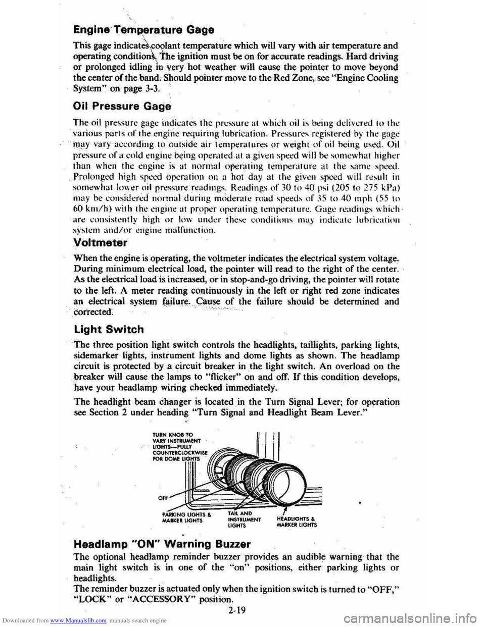
The three position light switch controls the headlights, taillights, parking lights,
sidemarker lights, instrument lights and dome lights as shown. The headlamp
circuit is protected by a circuit breaker in
the light switch. An overload on the
breaker will cause the lamps to "flicker" on and off. If this condition develops,
have your headlamp wiring checked immediately.
The headlight beam changer is located. in the
Turn Signal Lever; for operation
see Section 2 under heading "Tum Signal and Headlight Beam Lever."
TUIN KNOt TO VAr:t'INSTRUMENT lIGHTS_'UtLy COUNTERClOCKWISE RlR DOME
0"
MAltlCfIt LIGHTS , INSTRUMENT LIGHTS
Headlamp "ON" Warning Buzzer
The optional headlamp reminder buzzer provides an audible warning that the
main light switch is in one
of the "on" positions, either parking lights or
headlights.
The reminder buzzer
is actuated only when the ignition switch is turned to "OFF," "LOCK" or "ACCESSORY" position.
2-19
Page 64 of 95
Downloaded from www.Manualslib.com manuals search engine On all C-4 cars, a "CHECK ENGINE" light on the instrument panel is
designed to come on during engine starting , to let you know the bulb is working. (The light will stay on a short time after the engine starts.) If the light comes on while driving, service to the emission control system
may be required. See your Chevrolet dealer' as soon as possible for an inspection of the system. Continued driving without having the C-4 System serviced _ could eventually
cause damage
to the emission control system . It could also affect fuel
e conomy and drivabili -ty.
ENGINE OIL AND FILTER RECOMMENDATIONS • Engine oils' are labeled on 'the containers with various API (American
Petroleum Institute) designations 6f quality. Use engine oils that are labeled
5E or SE/CC. Do not use oils labeled only SA, 5B, 5C, SD, CA, CB, CC or CD; _or oils with the combination label SE and CD (SE/CD). Higher
quality oils labeled SF will be introduced soon (late 1979, or 1980). These SF oils are preferred and should be used when available.
• The oil and filter change intervals for your engine are based on the use of SE-quality or SF-quality oils and ,high- quality filters such as AC oil filters. Using oils other than SE-quality or SF-quality oils, or oil change intervals
longer than recommended. could reduce -engine life and might affect your
warranty.
• Your engine was filled with a high·quality engine oil when it was built. You do ,not have to change this oil before the suggested change period.
•
If your normal driving does nQt include one or more of the four "severe service" conditions listed below. change the oil every 7,500 miles (12 000 ' kilometers) or 12 months, whichever comes first. Change the oillilter at the
first oil change. then every second oil change, if mileage (7,500 miles or 12
000. kilom~ters) determines .w ,hen you change the oil. If _time (12 months)
determines when you change the oil, change the filter with every oil change.
• Change the oil and oil filter every 3,000 miles (4 800 kilometers) , or three
months if you often drive under one or more of these 'severe service·,~.
conditions: • Driving in dusty areas
• Towing ,3 trailer
• Frequent idling or idling for long periods
• Driving 4 miles (6 kilometers) br'less in freezing weather,o~other short trips in cold weather, where the engine does not thoTough ,ly warm up.
• Change the oil and oil filter as soon as -possible after driving in a dust
storm.
Oil Viscosity
Engine oil viscosity (thickness) has an effect on fuel economy. Lowec viscosity
engine oils can provide increased , fuel " economy; however, higher temperature
weather conditions require higher viscosity engine oils for satisf~ctory lubrication.
To. get the best fuel economy with your-1980 Chevrolet, -iou should use -,, ' .
fuel. 'saviiJ.&:_engine oil ohhe_ proper viscosity. These oils call_ be found. in serviCe
stations and other retail stores. They are-identified by words such as: "Energy Saving," "Conserves Gasoline," "Gas Saving," "Gasoline Saving," '''Friction
Reducing," "Improved Gasoline Mileage" or "Fuel Saving."
The following chart lists the engine ' oil viscosities recommended for the
temperature range you expect before the next oil change. For lemperalures above ,_18°C (O"F),SAE lOW-30 is -the preferred viscosity grade. Ircold-weather starting
problems
are encountered at temperatures below -lSoC (
5-3
Page 66 of 95
Downloaded from www.Manualslib.com manuals search engine NOTICE: You cannot read the correct fluid level if you have just driven the car for a long time at high speed, in city traffic in hot weather, or if the car has been pulling a trailer. Wait. until the fluid has cooled down (about 30 minutes).
Remove the dipstick located on the driver's side forward of the cowl. Carefully
touch the wet end of the dipstick to find out if the fluid is cool, warm or hot. Wipe
it clean and push it back in until the cap seats. Pull
out the dipstick and read the
fluid level.
• If it felt cool or warm (about room temperature), the level should be
between the dimples above the "Full" mark.
• If it was too hot to hold. the level should be at or in the hatched area.
Add just enough DEXRON-®n fluid to fill the transaxle. It takes only 0.5 liter
(one pint)to raise the level from "Add" to "Full" with a hot transaxle.
Do not overfill the transaxle. Overfilling can cause foaming and loss of fluid, which
could result in transaxle damage.
Automatic Transaxle Drain Intervals
Change the transmission fluid and change the filter (or clean the screen) as
outlined in Section
A of the Maintenance Schedule folder.
ELECTRIC FAN
CAUTION: Keep hands, tools, and clothing away from the angine cooling fan to help prevent personal injury. This fan is electric and can come on whether or not the engine is running. The fan can start automatically in response to a heat sensor when the ignition is in the "Run" position.
ENGINE COOLING SYSTEM
The coolant recovery system is standard. The coolant in the radiator expands with
heat, and the overflow collects in the recovery tank. When the system cools down,
the coolant
is drawn back into the radiator.
The cooling system was filled at the factory with a quality coolant that meets
GM Specification 1899-M. The cooling system is designed to use coolant (a mixture
of water and ethylene glycol antifreeze) rather than plain water. The coolant
solution should be used year round. It has many advantages, such as:
• provides freezing protection down to _37°C, (-34°P)
•
provides boiling protection up to 128QC, (262°P)
•
protects against rust and corrosion in the cooling system,
• maintains the proper engine temperature for efficient operation and emission
control, and
• allows proper operation of the coolant temperature light (or gage).
See Section A of the Maintenance Schedule folder to find out when the coolant
must
be replaced.
COOLING SYSTEM CARE
Check the cooling system at regular intervals, such as during fuel stops. You
usually do not need to remove the radiator cap to check the coolant level. Lift
the engine hood and look at the "see through" coolant recovery tank. When the
engine
is cold, the coolant level -should be at or slightly above the "Full Cold"
mark on the tank. When the engine has fully warmed up, the level should be at ')r slightly below the "Full Hot" mark on the tank. If the coolant level is low,
5-5
Page 68 of 95
Downloaded from www.Manualslib.com manuals search engine 3. Stop the engine. Open the radiator drain valve to drain the coolant. (Drainage
may be speeded by removing the drain plugs in the block.)
4. Close the drain valve (install block drain plugs, if removed). Add water until
the system is filled and run the engine until the upper radiator hose is hot again.
5. Repeat steps 3 and 4 several times until the drained liquid is nearly colorless.
6. Drain the system and then close the radiator drain valve tightly. (Install block
drain plugs, if removed.)
7. Disconnect all hoses from the coolant recovery tank. Remove the tank and
pour out any fluid. Scrub and clean the inside of the tank with soap and water.
Flush it well with clean water,
then drain it. Reinstall the tank and hoses.
8. Add enough water and ethylene glycol antifreeze (meeting GM Specification
1899-M)to provide the required cooling, freezing, and corrosion protection. Use a solution that is at least 50 percent antifreeze, but no more than 70
percent antifreeze. Fill the radiator to the base of the filler neck and fill the
coolant recovery
tank to the "Full Hot" mark. Put the recovery tank cap back
on.
9. Run the engine, with the radiator cap removed, until the upper radiator hose
is hot.
10. With the engine idling, add coolant to the radiator until it reaches the bottom
of the filler neck. Install the radiator cap, making sure the arrows on the cap line up with the overflow. tube.
It is the owner's responsibility to:
• Maintain cooling system freeze protection at _37°C (_34°F) to ensure
protection against corrosion and loss of coolant from boiling. (A SO/50
mixture of water and ethylene glycol antifreeze will provide freeze protection
to ~ 37°C ore -34°P.) You should do this even if you don't expect freezing
temperatures.
• Add ethylene glycol base antifreeze that meets GM Specification 1899-M
when antifreeze
hasto be added because of coolant loss or for more protection
' against freezing at temperatures lower than _37°C (-·J4°P).
NOTICE: Do not use alcohol or methanol-base antifreeze. or plain water alone. in your vehicle at any time. They will boil at a lower pOint than that at which the hot light indicator (or temperature gage) works. and they do not provide proper protection against corrosion.
Radiator Pressure Cap
The radiator cap, a 105 kPa(15 psi) pressure type, must be installed tightly,
otherwise coolant may be lost and damage to engine may result from overheating.
Radiator pressure caps should be checked periodically for proper operation.
If
replacement is required, an AC cap is recommended.
Thermostat
The engine coolant temperature is controlled by a thermostat. It stops coolant flow
through the radiator until a preset temperature is reached. This thermostat is
installed in
the engine coolant outlet on the engine block. The same thermostat is used in both winter and summer. When a replacement is needed, AC~Delco parts
are recommended.
5-7
Page 90 of 95
Downloaded from www.Manualslib.com manuals search engine Switch Headlights .... TEMP (Temperature) .. Locks Door ...
2~19 2-17 1-2
Ignition ............................................. .. 2-5 1-1 2-2
2-25 Keys .. Theft Protection .. Lowering Seats .. Love Seat, Child & Infant: .. Lugglige/Cargo Capacity ... Luggage Rack ... Maintenance Record .. Maintenance Schedule .. Manual Transaxle Clutch Adjustment. .. .
1-10 5-11 2·29 7-12 5-.1
Maintenance ........................................... . 5-8
5-8
2-11
2· 10 2-12 4-1 4-5
1-3
Operating Tips .. Operation .. Shift Speeds. Metal Cleaners .. Metal Damage, Body ... Mirrors, Rearview .. Mobile Radios-. Monoxide Caution, Carbon .. . 2-25 2-1
2-1 2-2
2-2
2-15 Muffler ............................................... . New Car Break-In Period Octane Rating, Gasoline ... Odometer Oil, Engine Capacity .. Change Interval.. Dipstick ... Filter ... PreSsure Gage .. Pressure Light... Recommendation (Gas) .. OIL Light.. Openings, Roof... Opening The Hatchback ... Hood .. Windows ..
6-.1 5-3 (inside Back Cover) 5-3,7·1 2·1-9 2-17
5-3
2-17 (See "Roofs")
2·26 (Inside Back Cover) 1-5 Operating Speeds, New Car... 2-2 Operating Tips Fuel Economy.. 2-4 Trailer Towing.. 1-13 Transaxle... 2-9 Ventilation System.. 2.20 Operation in Foreign Countries.. 2"3 Outside Rearview Mirror.. 1.3 Overheating, Engine.. 3-3 Overseas Operation.. 2.3 Owner Assistance.. 6-1 Owner's Record... 7-11 Oxygen Sensor., 5.2 Paint Care.. 4-4
Paint Damage .. Parking;. Parking Brake .. Parking Lights .. PCV Valve & Filter .. Peda'·TI"avel, Brake ... Pedal Travel, Clutch .. Polishing & Waxing .. Pollution Control Power
4-' 2-. 2-14 7-3 7·2 2-14 5~8
.-. (See "Emission Contron
7-8
Antennas Brakes .. Door Locks .... Seats ... Steering Pressure, Oil Light ... Pressure. Tire Inflation ... Pulse Wiper ...
2-25
2-14
1-2 1-' 2·12
2-15
5-11
2-7
Pushing to Start ................................ .. 5-2 Radiator Antifreeze (Coolant) .. Cap, Prassure .. Checking Level .. Overheating .. Thermostat...
Radios & Antennas ... Raising Seats ... Rear Cargo Cover ...................... .. Compartment .. . Window Defogger .. Trailering .. Rearview Mirrors .. Reclining Seats .. Recovery Tank, Coolant .. Release
Hatc.hback
Hood .. Seatback Latch ... Reminder Lights ....
Replacement Fasteners
5-5 5-. 5-5 3-3 5-7
2-23 -2-25
2-25
2-:27
2-2,2-28 2-21 '·11 1-3 1-' 5-5
2-25 (Inside Back Cover)
1-' (See "Lights") 5-1
5-1 Replacement Maintenance Schedule .. Raplacement Owner's·Manual... 7-13 Replacement Parts ............. ....................... 7-2 Restraints .. Rocking Car When Stuck .. Roofs Carrying Cargo On ... Luggage Carrier .. Rack .. Vinyl .. Vista-Vent. ... Rotation, Tire .. Rustproofing .. Rust Protection ... Sefety Belts .. Seats (See
"Seat Belts") 3-7
1-3,2-2,9 2·29 2·29
'-5 2-26 5-12
'-5 '-5 (See "Seat Belts")
Adjustment.. 1-4 Child... 1-10 Folding.. 2-25 Latches..
1-5 Reclining.... . '-4 Seat Belts Care.. 4.3 Child Restraint ............................................ 1.10 Inspection.. 1-10 Lap/Shoulder.. 1-6 Light/Buzzer Reminder... 1;8 Pregn~nt Women .. Rear Seat. ... Self-Adjusting Brakes .. SENSOR Indicator ..
1-8 2-25 2-14 2-18,5-2 Sensor, Oxygen.... 2-18,5-2 Service & Maintenance.. 5-1 Service Station Information (InSide Back Cover) Sheet Metlll Damage... 4-5