fuses CHEVROLET CLASSIC 2004 Owners Manual
[x] Cancel search | Manufacturer: CHEVROLET, Model Year: 2004, Model line: CLASSIC, Model: CHEVROLET CLASSIC 2004Pages: 348, PDF Size: 5.32 MB
Page 105 of 348
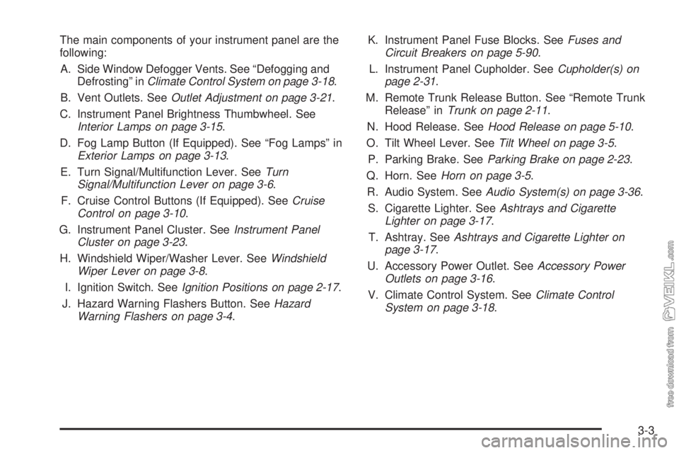
The main components of your instrument panel are the
following:
A. Side Window Defogger Vents. See “Defogging and
Defrosting” inClimate Control System on page 3-18.
B. Vent Outlets. SeeOutlet Adjustment on page 3-21.
C. Instrument Panel Brightness Thumbwheel. See
Interior Lamps on page 3-15.
D. Fog Lamp Button (If Equipped). See “Fog Lamps” in
Exterior Lamps on page 3-13.
E. Turn Signal/Multifunction Lever. SeeTurn
Signal/Multifunction Lever on page 3-6.
F. Cruise Control Buttons (If Equipped). SeeCruise
Control on page 3-10.
G. Instrument Panel Cluster. SeeInstrument Panel
Cluster on page 3-23.
H. Windshield Wiper/Washer Lever. SeeWindshield
Wiper Lever on page 3-8.
I. Ignition Switch. SeeIgnition Positions on page 2-17.
J. Hazard Warning Flashers Button. SeeHazard
Warning Flashers on page 3-4.K. Instrument Panel Fuse Blocks. SeeFuses and
Circuit Breakers on page 5-90.
L. Instrument Panel Cupholder. SeeCupholder(s) on
page 2-31.
M. Remote Trunk Release Button. See “Remote Trunk
Release” inTrunk on page 2-11.
N. Hood Release. SeeHood Release on page 5-10.
O. Tilt Wheel Lever. SeeTilt Wheel on page 3-5.
P. Parking Brake. SeeParking Brake on page 2-23.
Q. Horn. SeeHorn on page 3-5.
R. Audio System. SeeAudio System(s) on page 3-36.
S. Cigarette Lighter. SeeAshtrays and Cigarette
Lighter on page 3-17.
T. Ashtray. SeeAshtrays and Cigarette Lighter on
page 3-17.
U. Accessory Power Outlet. SeeAccessory Power
Outlets on page 3-16.
V. Climate Control System. SeeClimate Control
System on page 3-18.
3-3
Page 108 of 348
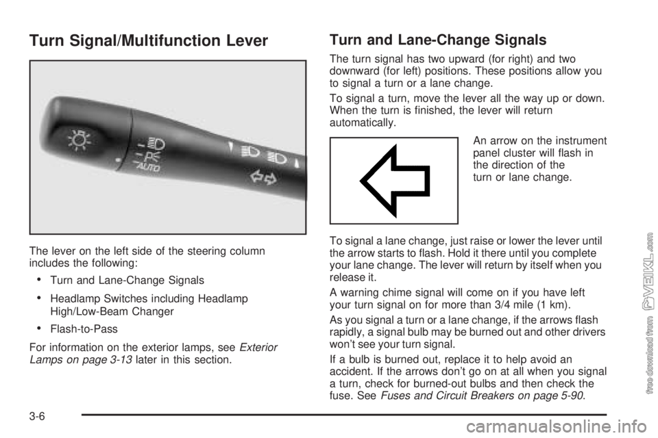
Turn Signal/Multifunction Lever
The lever on the left side of the steering column
includes the following:
•Turn and Lane-Change Signals
•Headlamp Switches including Headlamp
High/Low-Beam Changer
•Flash-to-Pass
For information on the exterior lamps, seeExterior
Lamps on page 3-13later in this section.
Turn and Lane-Change Signals
The turn signal has two upward (for right) and two
downward (for left) positions. These positions allow you
to signal a turn or a lane change.
To signal a turn, move the lever all the way up or down.
When the turn is finished, the lever will return
automatically.
An arrow on the instrument
panel cluster will flash in
the direction of the
turn or lane change.
To signal a lane change, just raise or lower the lever until
the arrow starts to flash. Hold it there until you complete
your lane change. The lever will return by itself when you
release it.
A warning chime signal will come on if you have left
your turn signal on for more than 3/4 mile (1 km).
As you signal a turn or a lane change, if the arrows flash
rapidly, a signal bulb may be burned out and other drivers
won’t see your turn signal.
If a bulb is burned out, replace it to help avoid an
accident. If the arrows don’t go on at all when you signal
a turn, check for burned-out bulbs and then check the
fuse. SeeFuses and Circuit Breakers on page 5-90.
3-6
Page 118 of 348
Battery Run-Down Protection
Your vehicle has a battery run-down protection feature
designed to protect your vehicle’s battery.
When any interior lamp (trunk, reading, footwell, visor
vanity or glove box) is left on when the ignition is turned
off, the battery run-down protection system will
automatically shut the lamp(s) off after 20 minutes. This
will avoid draining the battery.
To reactivate the interior lamps, do one of the following:
•Turn on the ignition,
•turn the exterior lamp control off and then on,
•open a door,
•press any remote keyless entry transmitter button
(if equipped),
•press the remote trunk release button, or
•press the power door lock switch.
The battery run-down feature will also be activated
when any door on the vehicle is left open and the
ignition is in OFF.
Accessory Power Outlets
With accessory power outlets you can plug in auxiliary
electrical equipment such as a cellular telephone or
CB radio.
The accessory power outlet is located to the right of the
ashtray.
Notice:Leaving electrical equipment on for
extended periods will drain the battery. Always turn
off electrical equipment when not in use and do
not plug in equipment that exceeds the maximum
amperage rating.
Certain electrical accessories may not be compatible
with the accessory power outlet and could result
in blown vehicle or adapter fuses. If you experience a
problem see your dealer for additional information
on accessory power outlets.
3-16
Page 189 of 348
4. To prevent your battery from draining while the
vehicle is being towed, remove the following
fuses from the driver’s side instrument panel fuse
block: A) Wiper, G) Powertrain Control Module
and J) Body Function Control Module. See
“Instrument Panel Fuse Block (Driver’s Side)” in
Fuses and Circuit Breakers on page 5-90for
location of these fuses.
5. Turn the ignition switch to ACCESSORY.
6. Shift your transaxle to NEUTRAL (N).
7. Release the parking brake.
Remember to install the fuses once you reach your
destination. To reinstall a fuse:
1. Set the parking brake.
2. Remove the key from the ignition switch.
3. Reinstall the fuse.
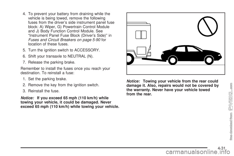
Notice:If you exceed 65 mph (110 km/h) while
towing your vehicle, it could be damaged. Never
exceed 65 mph (110 km/h) while towing your vehicle.Notice:Towing your vehicle from the rear could
damage it. Also, repairs would not be covered by
the warranty. Never have your vehicle towed
from the rear.
4-31
Page 204 of 348
Appearance Care............................................5-80
Cleaning the Inside of Your Vehicle.................5-80
Care of Safety Belts......................................5-83
Weatherstrips...............................................5-83
Cleaning the Outside of Your Vehicle..............5-83
Sheet Metal Damage.....................................5-85
Finish Damage.............................................5-85
Underbody Maintenance................................5-86
Chemical Paint Spotting.................................5-86
Vehicle Care/Appearance Materials..................5-86
Vehicle Identi�cation......................................5-88
Vehicle Identification Number (VIN).................5-88
Service Parts Identification Label.....................5-88Electrical System............................................5-89
Add-On Electrical Equipment..........................5-89
Headlamp Wiring..........................................5-89
Windshield Wiper Fuses................................5-89
Power Windows and Other Power Options.......5-89
Fuses and Circuit Breakers............................5-90
Capacities and Speci�cations..........................5-95
Normal Maintenance Replacement Parts..........5-96
Section 5 Service and Appearance Care
5-2
Page 215 of 348
A. Engine Coolant Surge Tank. SeeCooling System on
page 5-25.
B. Ground. SeeJump Starting on page 5-39.
C. Engine Oil Dipstick. See “Checking Engine Oil” in
Engine Oil on page 5-13.
D. Engine Oil Fill Cap. See “When to Add Engine Oil”
inEngine Oil on page 5-13.
E. Brake Fluid Reservoir. See “Brake Fluid” inBrakes
on page 5-34.
F. Power Steering Fluid Reservoir. SeePower Steering
Fluid on page 5-31.
G. Engine Compartment Fuse Block. SeeFuses and
Circuit Breakers on page 5-90.
H. Engine Air Cleaner/Filter. SeeEngine Air
Cleaner/Filter on page 5-17.
I. Battery. SeeBattery on page 5-38.
J. Windshield Washer Fluid Reservoir. SeeWindshield
Washer Fluid on page 5-32.Engine Oil
Checking Engine Oil
It is a good idea to check your engine oil every time you
get fuel. In order to get an accurate reading, the oil
must be warm and the vehicle must be on level ground.
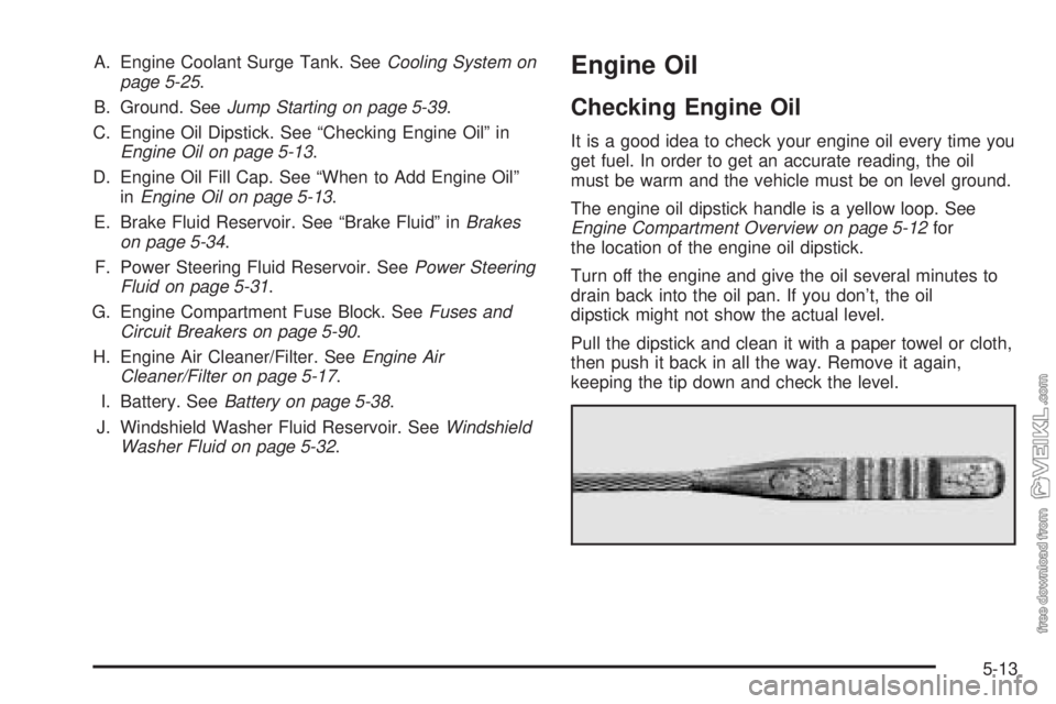
The engine oil dipstick handle is a yellow loop. See
Engine Compartment Overview on page 5-12for
the location of the engine oil dipstick.
Turn off the engine and give the oil several minutes to
drain back into the oil pan. If you don’t, the oil
dipstick might not show the actual level.
Pull the dipstick and clean it with a paper towel or cloth,
then push it back in all the way. Remove it again,
keeping the tip down and check the level.
5-13
Page 291 of 348
Electrical System
Add-On Electrical Equipment
Notice:Don’t add anything electrical to your vehicle
unless you check with your dealer �rst. Some
electrical equipment can damage your vehicle and
the damage wouldn’t be covered by your warranty.
Some add-on electrical equipment can keep other
components from working as they should.
Your vehicle has an air bag system. Before attempting
to add anything electrical to your vehicle, see
Servicing Your Air Bag-Equipped Vehicle on page 1-62.
Headlamp Wiring
The headlamp wiring is protected by fuses, one for each
headlamp, in the fuse block. An electrical overload
will cause the lamps to turn off. If this happens, have
your headlamp wiring checked right away.
Windshield Wiper Fuses
The windshield wiper motor is protected by an internal
circuit breaker and a fuse. If the motor overheats due to
heavy snow, etc., the wiper will stop until the motor
cools. If the overload is caused by some electrical
problem and not snow, etc., be sure to get it fixed.
Power Windows and Other Power
Options
Circuit breakers in the fuse block protect the power
windows and other power accessories. When the current
load is too heavy, the circuit breaker opens and
closes, protecting the circuit until the problem is fixed or
goes away.
5-89
Page 292 of 348
Fuses and Circuit Breakers
The wiring circuits in your vehicle are protected from
short circuits by a combination of fuses, circuit breakers
and fusible thermal links in the wiring itself.
Look at the silver-colored band inside the fuse. If the
band is broken or melted, replace the fuse. Be sure you
replace a bad fuse with a new one of the identical
size and rating.
If you ever have a problem on the road and don’t have
a spare fuse, you can borrow one that has the same
amperage. Just pick a feature of your vehicle that
you can get along without – like the radio or cigarette
lighter – and use its fuse, if it is the correct amperage.
Replace it as soon as you can.
There are three fuse blocks in your vehicle: two
instrument panel fuse blocks and the engine
compartment fuse block.
There is a fuse puller located on the engine
compartment fuse block. It can be used to easily
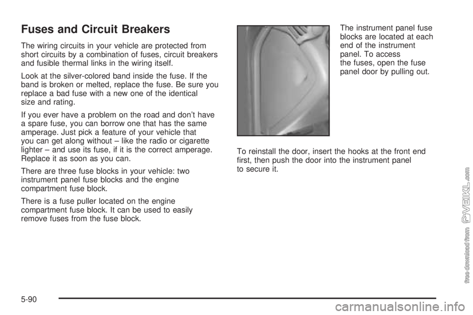
remove fuses from the fuse block.The instrument panel fuse
blocks are located at each
end of the instrument
panel. To access
the fuses, open the fuse
panel door by pulling out.
To reinstall the door, insert the hooks at the front end
first, then push the door into the instrument panel
to secure it.
5-90
Page 293 of 348
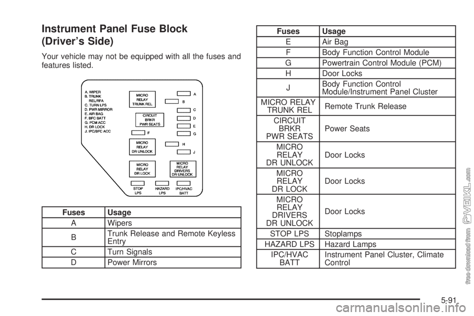
Instrument Panel Fuse Block
(Driver’s Side)
Your vehicle may not be equipped with all the fuses and
features listed.
Fuses Usage
A Wipers
BTrunk Release and Remote Keyless
Entry
C Turn Signals
D Power Mirrors
Fuses Usage
E Air Bag
F Body Function Control Module
G Powertrain Control Module (PCM)
H Door Locks
JBody Function Control
Module/Instrument Panel Cluster
MICRO RELAY
TRUNK RELRemote Trunk Release
CIRCUIT
BRKR
PWR SEATSPower Seats
MICRO
RELAY
DR UNLOCKDoor Locks
MICRO
RELAY
DR LOCKDoor Locks
MICRO
RELAY
DRIVERS
DR UNLOCKDoor Locks
STOP LPS Stoplamps
HAZARD LPS Hazard Lamps
IPC/HVAC
BATTInstrument Panel Cluster, Climate
Control
5-91
Page 294 of 348
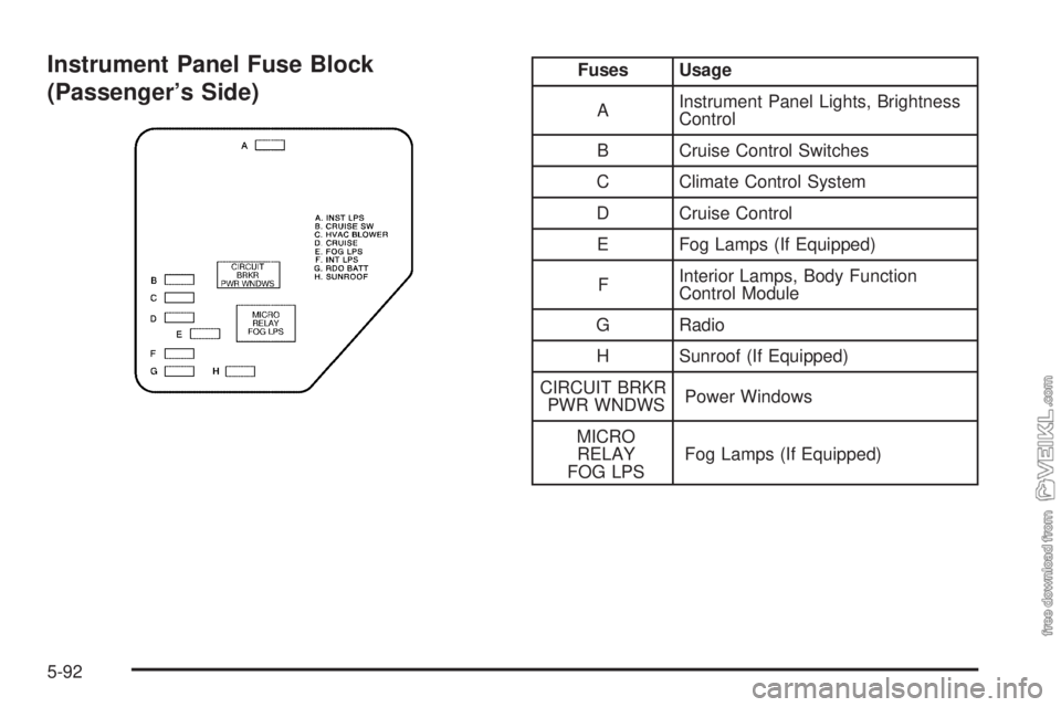
Instrument Panel Fuse Block
(Passenger’s Side)Fuses Usage
AInstrument Panel Lights, Brightness
Control
B Cruise Control Switches
C Climate Control System
D Cruise Control
E Fog Lamps (If Equipped)
FInterior Lamps, Body Function
Control Module
G Radio
H Sunroof (If Equipped)
CIRCUIT BRKR
PWR WNDWSPower Windows
MICRO
RELAY
FOG LPSFog Lamps (If Equipped)
5-92