tow CHEVROLET COLORADO 2023 Workshop Manual
[x] Cancel search | Manufacturer: CHEVROLET, Model Year: 2023, Model line: COLORADO, Model: CHEVROLET COLORADO 2023Pages: 362, PDF Size: 13.62 MB
Page 229 of 362
Chevrolet Colorado Owner Manual (GMNA-Localizing-U.S./Canada/Mexico-
15274222) - 2022 - CRC - 11/2/21
228 Driving and Operating
Towing Equipment
Hitches
Always use the correct hitch equipment for
your vehicle. Crosswinds, large trucks going
by, and rough roads can affect the trailer
and the hitch.
Proper hitch equipment for your vehicle
helps maintain control of the vehicle-trailer
combination. Many trailers can be towed
using a weight-carrying hitch which has a
coupler latched to the hitch ball, or a tow
eye latched to a pintle hook. Other trailers
may require a weight-distributing hitch that
uses spring bars to distribute the trailer
tongue weight between your vehicle and
trailer axles. See“Maximum Trailer Tongue
Weight” underTrailer Towing 0223 for
weight limits with various hitch types.
Avoid sharp turns when using a step-bumper
hitch to prevent damage. Make wider turns
to prevent contact between your trailer and
your bumper.
Consider using mechanical sway controls
with any trailer. Ask a trailering professional
about sway controls or refer to the trailer
manufacturer's recommendations and
instructions.
Weight-Distributing Hitch and
Adjustment
A weight-distributing hitch may be useful
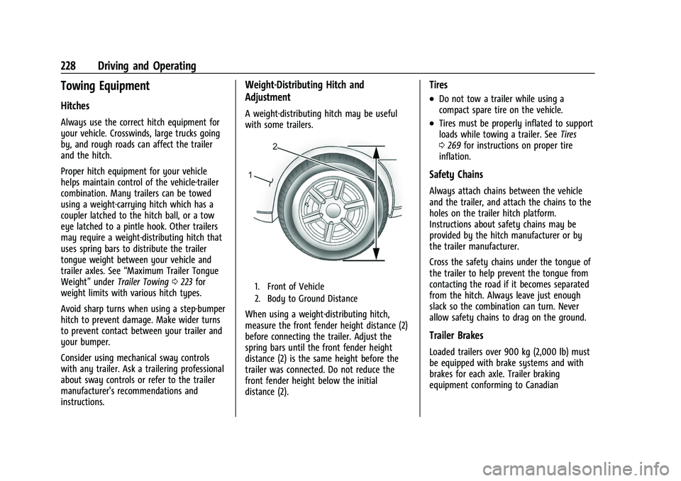
with some trailers.
1. Front of Vehicle
2. Body to Ground Distance
When using a weight-distributing hitch,
measure the front fender height distance (2)
before connecting the trailer. Adjust the
spring bars until the front fender height
distance (2) is the same height before the
trailer was connected. Do not reduce the
front fender height below the initial
distance (2).
Tires
.Do not tow a trailer while using a
compact spare tire on the vehicle.
.Tires must be properly inflated to support
loads while towing a trailer. See Tires
0 269 for instructions on proper tire
inflation.
Safety Chains
Always attach chains between the vehicle
and the trailer, and attach the chains to the
holes on the trailer hitch platform.
Instructions about safety chains may be
provided by the hitch manufacturer or by
the trailer manufacturer.
Cross the safety chains under the tongue of
the trailer to help prevent the tongue from
contacting the road if it becomes separated
from the hitch. Always leave just enough
slack so the combination can turn. Never
allow safety chains to drag on the ground.
Trailer Brakes
Loaded trailers over 900 kg (2,000 lb) must
be equipped with brake systems and with
brakes for each axle. Trailer braking
equipment conforming to Canadian
Page 230 of 362
Chevrolet Colorado Owner Manual (GMNA-Localizing-U.S./Canada/Mexico-
15274222) - 2022 - CRC - 11/2/21
Driving and Operating 229
Standards Association (CSA) requirement
CAN3-D313, or its equivalent, is
recommended.
State or local regulations may require
trailers to have their own braking system if
the loaded weight of the trailer exceeds
certain minimums that can vary from state
to state. Read and follow the instructions for
the trailer brakes so they are installed,
adjusted, and maintained properly. Never
attempt to tap into your vehicle's hydraulic
brake system. If you do, both the vehicle
anti-lock brakes and the trailer brakes may
not function, which could result in a crash.
Trailer Wiring Harness
For vehicles not equipped with heavy-duty
trailering, a harness is secured underneath
the left side of the vehicle, next to the spare
tire. The harness requires the installation of
a trailer connector, which is available
through your dealer. The seven-wire harness
contains the following trailer circuits:
.Yellow: Left stop/turn signal
.Green: Right stop/turn signal
.Brown: Taillamps/parking lamps
.Black: Ground
.Gray: Back-up lamps
.Orange: Battery feed
.Blue: Trailer brake
To help charge a remote (non-vehicle)
battery, press the Tow/Haul Mode button
on the center stack. If the trailer is too light
for Tow/Haul Mode, turn on the headlamps
to help charge the battery.
Trailer Brake Control Wiring Harness
A four-wire harness, without connector, is
secured behind the left side kick panel. The
harness contains the following circuits:
.Red/Green: Battery feed
.Black: Ground
.White/Blue: Brake signal to controller
.Blue: Trailer Brake power to trailer
connector To remove the left side kick panel, start at
the front of the panel pulling toward the
rear of the vehicle and lift upward to
disengage the integral clips.
Turn Signals When Towing a Trailer
When properly connected, the trailer turn
signals will illuminate to indicate the vehicle
is turning, changing lanes, or stopping.
When towing a trailer, the arrows on the
instrument cluster will illuminate even if the
trailer is not properly connected or the bulbs
are burned out.
Tow/Haul Mode
For instructions on how to enter Tow/Haul
Mode, see
Tow/Haul Mode 0194.
Tow/Haul assists when pulling a heavy
trailer or a large or heavy load.
Tow/Haul Mode is designed to be most
effective when the vehicle and trailer
combined weight is at least 75% of the
vehicle's Gross Combined Weight Rating
(GCWR). See “Weight of the Trailer” under
Trailer Towing 0223.
Tow/Haul Mode is most useful when towing
a heavy trailer or carrying a large or
heavy load:
.through rolling terrain.
Page 231 of 362
Chevrolet Colorado Owner Manual (GMNA-Localizing-U.S./Canada/Mexico-
15274222) - 2022 - CRC - 11/2/21
230 Driving and Operating
.in stop-and-go traffic.
.in busy parking lots.
Operating the vehicle in Tow/Haul Mode
when lightly loaded or not towing will not
cause damage; however, it is not
recommended and may result in unpleasant
engine and transmission driving
characteristics and reduced fuel economy.
Integrated Trailer Brake Control System
The vehicle may have an Integrated Trailer
Brake Control (ITBC) system for use with
electric trailer brakes or most electric over
hydraulic trailer brake systems. These
instructions apply to both types of electric
trailer brakes.
This symbol is on the Trailer Brake Control
Panel on vehicles with an ITBC system. The
power output to the trailer brakes is
proportional to the amount of vehicle
braking. This available power output to the
trailer brakes can be adjusted to a wide
range of trailering situations. The ITBC system is integrated with the
vehicle’s brake, antilock brake, and
StabiliTrak/Electronic Stability Control (ESC)
systems. In trailering conditions that cause
the vehicle’s antilock brake or StabiliTrak/
ESC systems to activate, power sent to the
trailer's brakes will be automatically
adjusted to minimize trailer wheel lock-up.
This does not imply that the trailer has
StabiliTrak/ESC.
If the vehicle’s brake, anti-lock brake,
or StabiliTrak/ESC systems are not
functioning properly, the ITBC system may
not function fully or at all. Make sure all of
these systems are fully operational to allow
the ITBC system to function properly.
The ITBC system is powered through the
vehicle's electrical system. Turning the
ignition off will also turn off the ITBC
system. The ITBC system is fully functional
only when the ignition is in ON/RUN.{Warning
Connecting a trailer that has an air brake
system may result in reduced or
complete loss of trailer braking, including
increased stopping distance or trailer
instability which could result in serious
(Continued)
Warning (Continued)
injury, death, or property damage. Only
use the ITBC system with electric or
electric over hydraulic trailer brake
systems.
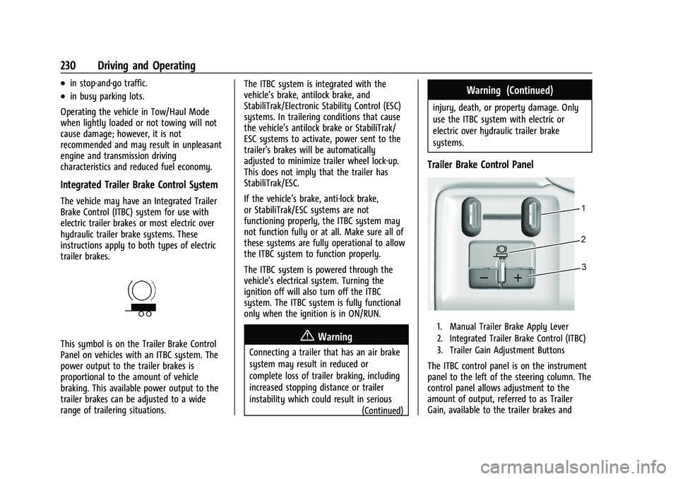
Trailer Brake Control Panel
1. Manual Trailer Brake Apply Lever
2. Integrated Trailer Brake Control (ITBC)
3. Trailer Gain Adjustment Buttons
The ITBC control panel is on the instrument
panel to the left of the steering column. The
control panel allows adjustment to the
amount of output, referred to as Trailer
Gain, available to the trailer brakes and
Page 232 of 362
Chevrolet Colorado Owner Manual (GMNA-Localizing-U.S./Canada/Mexico-
15274222) - 2022 - CRC - 11/2/21
Driving and Operating 231
allows manual application of the trailer
brakes. Use the ITBC control panel and the
DIC trailer brake display page to adjust and
display power output to the trailer brakes.
Trailer Brake DIC Display Page
The ITBC display page indicates:
.Trailer Gain setting
.Output to the trailer brakes
.Trailer connection
.System operational status
To display:
.Scroll through the DIC menu pages
.Press a Trailer Gain (+) or (−) button
.Activate the Manual Trailer Brake Apply
Lever
TRAILER GAIN: Press a Trailer Gain button to
recall the current Trailer Gain setting. Each
press and release of the gain buttons will
then change the Trailer Gain setting. Press
the Trailer Gain (+) or (−) to adjust. Press
and hold to continuously adjust the Trailer
Gain. To turn the output to the trailer off,
adjust the Trailer Gain setting to 0.0. This
setting can be adjusted from 0.0 to 10.0
with a trailer connected or disconnected. TRAILER OUTPUT: This displays anytime a
trailer with electric brakes is connected.
Output to the trailer brakes is based on the
amount of vehicle braking present and
relative to the Trailer Gain setting. Output is
displayed from 0 to 100% for each gain
setting.
The Trailer Output will indicate
“- - - - - -”on
the Trailer Brake Display Page whenever the
following occur:
.No trailer is connected.
.A trailer without electric brakes is
connected, no DIC message displays.
.A trailer with electric brakes has become
disconnected, a CHECK TRAILER WIRING
message displays on the DIC.
.There is a fault present in the wiring to
the trailer brakes, a CHECK TRAILER
WIRING message displays on the DIC.
.The ITBC system is not working due to a
fault, a SERVICE TRAILER BRAKE SYSTEM
message displays in the DIC.
Manual Trailer Brake Apply Lever
Slide this lever right to apply the trailer’s
electric brakes independent of the vehicle’s
brakes. Use this lever to adjust Trailer Gain
to achieve proper power output to the
trailer brakes. The trailer's and the vehicle's brake lamps will come on when either
vehicle brakes or manual trailer brakes are
applied and properly connected.
Trailer Gain Adjustment Procedure
Trailer Gain should be set for a specific
trailering condition and it must be
readjusted anytime vehicle loading, trailer
loading, or road surface conditions change.
{Warning
Trailer brakes that are over-gained or
under-gained may not stop the vehicle
and the trailer as intended and can result
in a crash. Always follow the instructions
to set the Trailer Gain for the proper
trailer stopping performance.
To adjust Trailer Gain for each towing
condition: 1. Drive the vehicle with the trailer attached on a level road surface
representative of the towing condition
and free of traffic at about 32–40 km/h
(20–25 mph) and fully apply the Manual
Trailer Brake Apply Lever.
Adjusting Trailer Gain at speeds lower
than 32–40 km/h (20–25 mph) may
result in an incorrect gain setting.
Page 233 of 362
Chevrolet Colorado Owner Manual (GMNA-Localizing-U.S./Canada/Mexico-
15274222) - 2022 - CRC - 11/2/21
232 Driving and Operating
2. Adjust the Trailer Gain, using the TrailerGain (+) or (-) adjustment buttons, to
just below the point of trailer wheel
lock-up, indicated by trailer wheel squeal
or tire smoke when a trailer wheel locks.
Trailer wheel lock-up may not occur if
towing a heavily loaded trailer. Adjust
the Trailer Gain to the highest allowable
setting for the towing condition.
3. Readjust Trailer Gain anytime vehicle loading, trailer loading, or road surface
conditions change or if trailer wheel
lock-up is noticed at any time while
towing.
Other ITBC-Related DIC Messages
TRAILER CONNECTED: This message will
briefly display when a trailer with electric
brakes is first connected to the vehicle. This
message will automatically turn off in about
10 seconds. This message can be
acknowledged before it automatically
turns off.
CHECK TRAILER WIRING: This message will
display if:
.The ITBC system first determines
connection to a trailer with electric brakes
and then the trailer harness becomes
disconnected from the vehicle. If the disconnect occurs while the vehicle
is stationary, this message will
automatically turn off in about
30 seconds. This message will also turn
off if it is acknowledged or if the trailer
harness is reconnected.
If the disconnect occurs while the vehicle
is moving, this message will continue
until the ignition is turned off. This
message will also turn off if it is
acknowledged or if the trailer harness is
reconnected.
.There is an electrical fault in the wiring to
the trailer brakes. This message will
continue as long as there is an electrical
fault in the trailer wiring. This message
will also turn off if it is acknowledged.
To determine whether the electrical fault is
on the vehicle side or trailer side of the
trailer wiring harness connection: 1. Disconnect the trailer wiring harness from the vehicle.
2. Turn the ignition off.
3. Wait 10 seconds, then turn the ignition back to RUN.
4. If the CHECK TRAILER WIRING message reappears, the electrical fault is on the
vehicle side. If the CHECK TRAILER WIRING message only
reappears when connecting the trailer wiring
harness to the vehicle, the electrical fault is
on the trailer side.
SERVICE TRAILER BRAKE SYSTEM: This
message will display when there is a
problem with the ITBC system. If this
message continues over multiple ignition
cycles, have the vehicle serviced.
If either the CHECK TRAILER WIRING or
SERVICE TRAILER BRAKE SYSTEM message
displays while driving, the ITBC system may
not be fully functional or may not function
at all. When traffic conditions allow,
carefully pull the vehicle over to the side of
the road and turn the ignition off. Check the
wiring connection to the trailer and turn the
ignition back on. If either of these messages
continues, either the vehicle or trailer needs
service.
A GM dealer may be able to diagnose and
repair problems with the trailer. However,
any diagnosis and repair of the trailer is not
covered under the vehicle warranty. Contact
your trailer dealer for assistance with trailer
repairs and trailer warranty information.
Page 234 of 362
Chevrolet Colorado Owner Manual (GMNA-Localizing-U.S./Canada/Mexico-
15274222) - 2022 - CRC - 11/2/21
Driving and Operating 233
Trailer Sway Control (TSC)
Vehicles with StabiliTrak/Electronic Stability
Control (ESC) have a Trailer Sway Control
(TSC) feature. Trailer sway is unintended
side-to-side motion of a trailer while towing.
If the vehicle is towing a trailer and the TSC
detects that sway is increasing, the vehicle
brakes are selectively applied at each wheel,
to help reduce excessive trailer sway.
If equipped with the Integrated Trailer Brake
Control (ITBC) system, and the trailer has an
electric brake system, StabiliTrak/ESC may
also apply the trailer brakes.
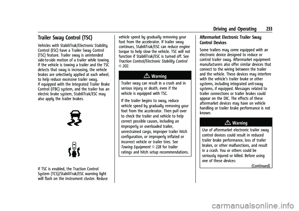
If TSC is enabled, the Traction Control
System (TCS)/StabiliTrak/ESC warning light
will flash on the instrument cluster. Reducevehicle speed by gradually removing your
foot from the accelerator. If trailer sway
continues, StabiliTrak/ESC can reduce engine
torque to help slow the vehicle. TSC will not
function if StabiliTrak/ESC is turned off. See
Traction Control/Electronic Stability Control
0
202.
{Warning
Trailer sway can result in a crash and in
serious injury or death, even if the
vehicle is equipped with TSC.
If the trailer begins to sway, reduce
vehicle speed by gradually removing your
foot from the accelerator. Then pull over
to check the trailer and vehicle to help
correct possible causes, including an
improperly or overloaded trailer,
unrestrained cargo, improper trailer hitch
configuration, or improperly inflated or
incorrect vehicle or trailer tires. See
Towing Equipment 0228 for trailer
ratings and hitch setup recommendations.
Aftermarket Electronic Trailer Sway
Control Devices
Some trailers may come equipped with an
electronic device designed to reduce or
control trailer sway. Aftermarket equipment
manufacturers also offer similar devices that
connect to the wiring between the trailer
and the vehicle. These devices may interfere
with the vehicle’s trailer brake or other
systems, including integrated anti-sway
systems, if equipped. Messages related to
trailer connections or trailer brakes could
appear on the DIC. The effects of these
aftermarket devices may have on vehicle
handling or trailer brake performance is not
known.
{Warning
Use of aftermarket electronic trailer sway
control devices could result in reduced
trailer brake performance, loss of trailer
brakes, or other malfunctions, and result
in a crash. You or others could be
seriously injured or killed. Before using
one of these devices: (Continued)
Page 237 of 362
Chevrolet Colorado Owner Manual (GMNA-Localizing-U.S./Canada/Mexico-
15274222) - 2022 - CRC - 11/2/21
236 Vehicle Care
Vehicle Care
General Information
General Information . . . . . . . . . . . . . . . . . . . 237
California Perchlorate MaterialsRequirements . . . . . . . . . . . . . . . . . . . . . . . . 237
Accessories and Modifications . . . . . . . . . 237
Vehicle Checks
Doing Your Own Service Work . . . . . . . . . 237
Hood . . . . . . . . . . . . . . . . . . . . . . . . . . . . . . . . . . 238
Engine Compartment Overview . . . . . . . . 239
Engine Oil . . . . . . . . . . . . . . . . . . . . . . . . . . . . . 242
Engine Oil Life System . . . . . . . . . . . . . . . . 244
Automatic Transmission Fluid . . . . . . . . . 245
Engine Air Cleaner/Filter . . . . . . . . . . . . . . . 245
Cooling System . . . . . . . . . . . . . . . . . . . . . . . 246
Engine Overheating . . . . . . . . . . . . . . . . . . . 249
Engine Fan . . . . . . . . . . . . . . . . . . . . . . . . . . . . 250
Washer Fluid . . . . . . . . . . . . . . . . . . . . . . . . . . 251
Brakes . . . . . . . . . . . . . . . . . . . . . . . . . . . . . . . . . 251
Brake Fluid . . . . . . . . . . . . . . . . . . . . . . . . . . . . 252
Battery - North America . . . . . . . . . . . . . . . 253
Four-Wheel Drive . . . . . . . . . . . . . . . . . . . . . . 254
Front Axle . . . . . . . . . . . . . . . . . . . . . . . . . . . . . 254
Rear Axle . . . . . . . . . . . . . . . . . . . . . . . . . . . . . . 254
Starter Switch Check . . . . . . . . . . . . . . . . . . . 255
Automatic Transmission Shift Lock Control Function Check . . . . . . . . . . . . . . 255
Ignition Transmission Lock Check . . . . . . 255 Park Brake and P (Park) Mechanism
Check . . . . . . . . . . . . . . . . . . . . . . . . . . . . . . . . 255
Wiper Blade Replacement . . . . . . . . . . . . . 256
Windshield Replacement . . . . . . . . . . . . . . 256
Gas Strut(s) . . . . . . . . . . . . . . . . . . . . . . . . . . . 256
Headlamp Aiming
Front Headlamp Aiming . . . . . . . . . . . . . . . 257
Bulb Replacement
Bulb Replacement . . . . . . . . . . . . . . . . . . . . . 257
Halogen Bulbs . . . . . . . . . . . . . . . . . . . . . . . . . 258
Headlamps, Front Turn Signal, Sidemarker, and Parking Lamps . . . . . . 258
Taillamps, Turn Signal, Stoplamps, and Back-Up Lamps . . . . . . . . . . . . . . . . . . . . . . 258
Center High-Mounted Stoplamp (CHMSL) and Cargo Lamp . . . . . . . . . . . 260
Electrical System
Electrical System Overload . . . . . . . . . . . . 260
Fuses and Circuit Breakers . . . . . . . . . . . . . 262
Engine Compartment Fuse Block . . . . . . 262
Instrument Panel Fuse Block . . . . . . . . . . 267
Wheels and Tires
Tires . . . . . . . . . . . . . . . . . . . . . . . . . . . . . . . . . . 269
All-Season Tires . . . . . . . . . . . . . . . . . . . . . . . 270
Winter Tires . . . . . . . . . . . . . . . . . . . . . . . . . . . 270
All-Terrain Tires . . . . . . . . . . . . . . . . . . . . . . . . 271
Tire Sidewall Labeling . . . . . . . . . . . . . . . . . . 271
Tire Designations . . . . . . . . . . . . . . . . . . . . . . 273 Tire Terminology and Definitions . . . . . . 273
Tire Pressure . . . . . . . . . . . . . . . . . . . . . . . . . . 275
Tire Pressure Monitor System . . . . . . . . . 276
Tire Pressure Monitor Operation . . . . . . . 277
Tire Inspection . . . . . . . . . . . . . . . . . . . . . . . . 280
Tire Rotation . . . . . . . . . . . . . . . . . . . . . . . . . . 280
When It Is Time for New Tires . . . . . . . . . 281
Buying New Tires . . . . . . . . . . . . . . . . . . . . . 282
Different Size Tires and Wheels . . . . . . . 283
Uniform Tire Quality Grading . . . . . . . . . 283
Wheel Alignment and Tire Balance . . . . 284
Wheel Replacement . . . . . . . . . . . . . . . . . . . 284
Tire Chains . . . . . . . . . . . . . . . . . . . . . . . . . . . . 285
If a Tire Goes Flat . . . . . . . . . . . . . . . . . . . . . 286
Tire Changing . . . . . . . . . . . . . . . . . . . . . . . . . 287
Compact Spare Tire . . . . . . . . . . . . . . . . . . . 296
Full-Size Spare Tire . . . . . . . . . . . . . . . . . . . . 297
Jump Starting
Jump Starting - North America . . . . . . . . 297
Towing the Vehicle
Towing the Vehicle . . . . . . . . . . . . . . . . . . . 300
Recreational Vehicle Towing . . . . . . . . . . . 301
Appearance Care
Exterior Care . . . . . . . . . . . . . . . . . . . . . . . . . . 304
Interior Care . . . . . . . . . . . . . . . . . . . . . . . . . . 308
Floor Mats . . . . . . . . . . . . . . . . . . . . . . . . . . . . . 311
Page 239 of 362
Chevrolet Colorado Owner Manual (GMNA-Localizing-U.S./Canada/Mexico-
15274222) - 2022 - CRC - 11/2/21
238 Vehicle Care
This vehicle has an airbag system. Before
attempting to do your own service work,
seeServicing the Airbag-Equipped Vehicle
0 42.
If equipped with remote vehicle start, open
the hood before performing any service
work to prevent remote starting the vehicle
accidentally. See Remote Vehicle Start 011.
Keep a record with all parts receipts and list
the mileage and the date of any service
work performed. See Maintenance Records
0 326.
Caution
Even small amounts of contamination can
cause damage to vehicle systems. Do not
allow contaminants to contact the fluids,
reservoir caps, or dipsticks.
Hood
{Warning
Turn the vehicle off before opening the
hood. If the engine is running with the
hood open, you or others could be
injured.
{Warning
Components under the hood can get hot
from running the engine. To help avoid
the risk of burning unprotected skin,
never touch these components until they
have cooled, and always use a glove or
towel to avoid direct skin contact.
Clear any snow from the hood before
opening.
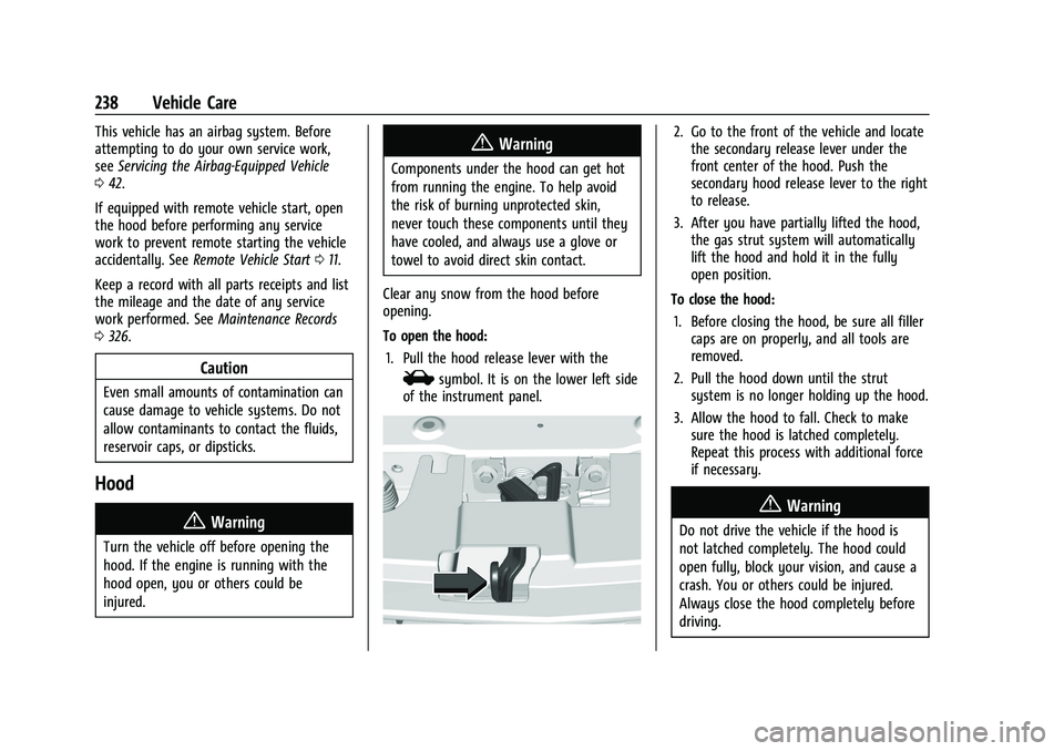
To open the hood: 1. Pull the hood release lever with the
isymbol. It is on the lower left side
of the instrument panel.
2. Go to the front of the vehicle and locate the secondary release lever under the
front center of the hood. Push the
secondary hood release lever to the right
to release.
3. After you have partially lifted the hood, the gas strut system will automatically
lift the hood and hold it in the fully
open position.
To close the hood: 1. Before closing the hood, be sure all filler caps are on properly, and all tools are
removed.
2. Pull the hood down until the strut system is no longer holding up the hood.
3. Allow the hood to fall. Check to make sure the hood is latched completely.
Repeat this process with additional force
if necessary.
{Warning
Do not drive the vehicle if the hood is
not latched completely. The hood could
open fully, block your vision, and cause a
crash. You or others could be injured.
Always close the hood completely before
driving.
Page 243 of 362
Chevrolet Colorado Owner Manual (GMNA-Localizing-U.S./Canada/Mexico-
15274222) - 2022 - CRC - 11/2/21
242 Vehicle Care
Engine Oil
For diesel engine vehicles, see“Engine Oil”
in the Duramax diesel supplement.
To ensure proper engine performance and
long life, careful attention must be paid to
engine oil. Following these simple, but
important steps will help protect your
investment:
.Use engine oil approved to the proper
specification and of the proper viscosity
grade. See “Selecting the Right Engine
Oil” in this section.
.Check the engine oil level regularly and
maintain the proper oil level. See
“Checking Engine Oil” and“When to Add
Engine Oil” in this section.
.Change the engine oil at the appropriate
time. SeeEngine Oil Life System 0244.
.Always dispose of engine oil properly. See
“What to Do with Used Oil” in this
section.
Checking Engine Oil
Check the engine oil level regularly, every
650 km (400 mi), especially prior to a long
trip. The engine oil dipstick handle is a loop.
See Engine Compartment Overview 0239 for
the location.
{Warning
The engine oil dipstick handle may be
hot; it could burn you. Use a towel or
glove to touch the dipstick handle.
If a low oil Driver Information Center (DIC)
message displays, check the oil level.
Follow these guidelines:
.To get an accurate reading, park the
vehicle on level ground. Check the engine
oil level after the engine has been off for
at least two hours. Checking the engine
oil level on steep grades or too soon after
engine shutoff can result in incorrect
readings. Accuracy improves when
checking a cold engine prior to starting.
Remove the dipstick and check the level.
.If unable to wait two hours, the engine
must be off for at least 15 minutes if the
engine is warm, or at least 30 minutes if
the engine is not warm. Pull out the
dipstick, wipe it with a clean paper towel
or cloth, then push it back in all the way.
Remove it again, keeping the tip down,
and check the level.
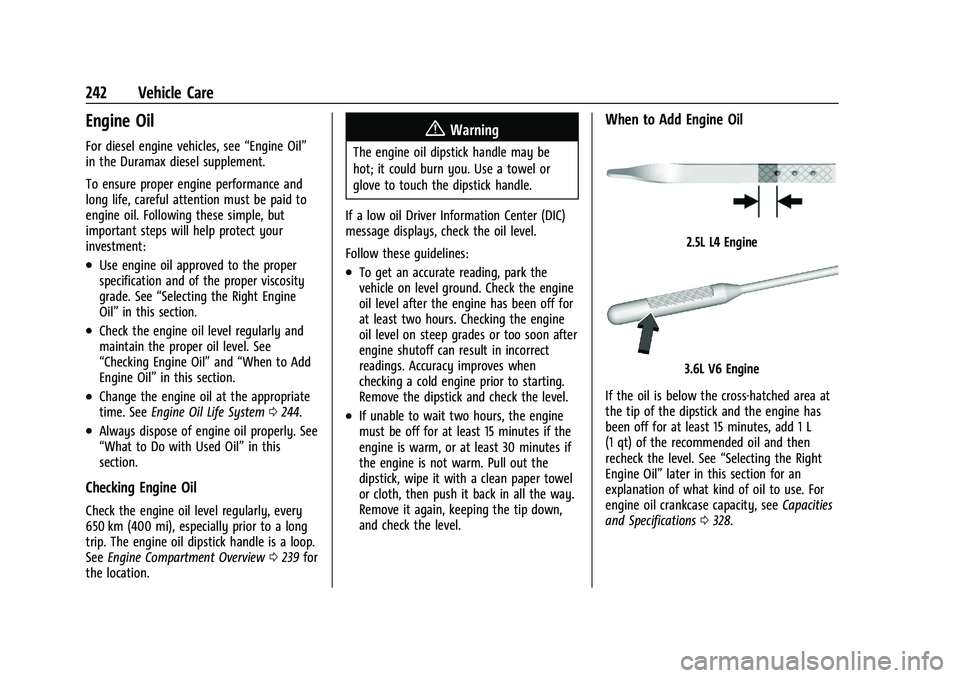
When to Add Engine Oil
2.5L L4 Engine
3.6L V6 Engine
If the oil is below the cross-hatched area at
the tip of the dipstick and the engine has
been off for at least 15 minutes, add 1 L
(1 qt) of the recommended oil and then
recheck the level. See “Selecting the Right
Engine Oil” later in this section for an
explanation of what kind of oil to use. For
engine oil crankcase capacity, see Capacities
and Specifications 0328.
Page 251 of 362
Chevrolet Colorado Owner Manual (GMNA-Localizing-U.S./Canada/Mexico-
15274222) - 2022 - CRC - 11/2/21
250 Vehicle Care
Caution
Do not run the engine if there is a leak
in the engine cooling system. This can
cause a loss of all coolant and can
damage the system and vehicle. Have
any leaks fixed right away.
If the decision is made not to lift the hood
when this warning appears, get service help
right away.
If the decision is made to lift the hood,
make sure the vehicle is parked on a level
surface.
Then check to see if the engine cooling fan
is running. If the engine is overheating, the
fan should be running. If it is not, do not
continue to run the engine and have the
vehicle serviced.
If Steam Is Coming from the Engine
Compartment
{Warning
Steam and scalding liquids from a hot
cooling system are under pressure.
Turning the pressure cap, even a little,
can cause them to come out at high (Continued)
Warning (Continued)
speed and you could be burned. Never
turn the cap when the cooling system,
including the pressure cap, is hot. Wait
for the cooling system and pressure cap
to cool.
If No Steam Is Coming from the Engine
Compartment
If an engine overheat warning is displayed
but no steam can be seen or heard, the
problem may not be too serious. Sometimes
the engine can get a little too hot when the
vehicle:
.Climbs a long hill on a hot day.
.Stops after high-speed driving.
.Idles for long periods in traffic.
If the overheat warning is displayed with no
sign of steam: 1. Turn the air conditioning off.
2. Turn the heater on to the highest temperature and to the highest fan
speed. Open the windows as necessary.
3. When it is safe to do so, pull off the road, shift to P (Park) or N (Neutral), and
let the engine idle. If the engine coolant temperature gauge is
no longer in the overheat zone, the vehicle
can be driven. Continue to drive the vehicle
slowly for about 10 minutes. Keep a safe
distance from the vehicle in front. If the
warning does not come back on, continue to
drive normally and have the cooling system
checked for proper fill and function.
If the warning continues, pull over, stop, and
park the vehicle right away.
If there is no sign of steam, idle the engine
for three minutes while parked. If the
warning is still displayed, turn off the
engine until it cools down.
Engine Fan
If the vehicle has a clutched engine cooling
fan, when the clutch is engaged, the fan
spins faster to provide more air to cool the
engine. In most everyday driving conditions,
the fan is spinning slower and the clutch is
not fully engaged. This improves fuel
economy and reduces fan noise. Under
heavy vehicle loading, trailer towing, and/or
high outside temperatures, the fan speed
increases as the clutch more fully engages,
so an increase in fan noise may be heard.
This is normal and should not be mistaken
as the transmission slipping or making extra