light CHEVROLET CORVAIR 1960 1.G Owners Manual
[x] Cancel search | Manufacturer: CHEVROLET, Model Year: 1960, Model line: CORVAIR, Model: CHEVROLET CORVAIR 1960 1.GPages: 38, PDF Size: 13.42 MB
Page 9 of 38
POWERGlIDE
PUSHING TO START
• Turn on key and move selector lever to Neutral. At
20 to 25 MPH move lever to "L."
• When engine starts, move selector lever to "D."
NOTE: Never tow to start.
TOWING
• Place selector lever in Neutral.
• If transmission or axle are malfunctioning, tow with
rear wheels raised.
• Never tow faster than 30 MPH.
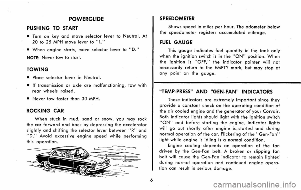
ROCKING CAR
When stuck in mud, sand or snow, you may rock
the car forward and back by depressing the accelerator
slightly and shifting the selector lever between" R" and
"D." Avoid excessive engine speed while performing
this operation.
~ -'.
6
SPEEDOMETER
Shows speed in miles per hour. The odometer below
the speedometer registers accumulated mileage.
FUEL GAUGE
This gauge indicates fuel quantity in the tank only
when the ignition switch is in the "ON" p')sition. When
the ignition is "OFF," the indicator pointer will not
necessarily return to the EMPTY mark, but may stop at
any point on the gauge.
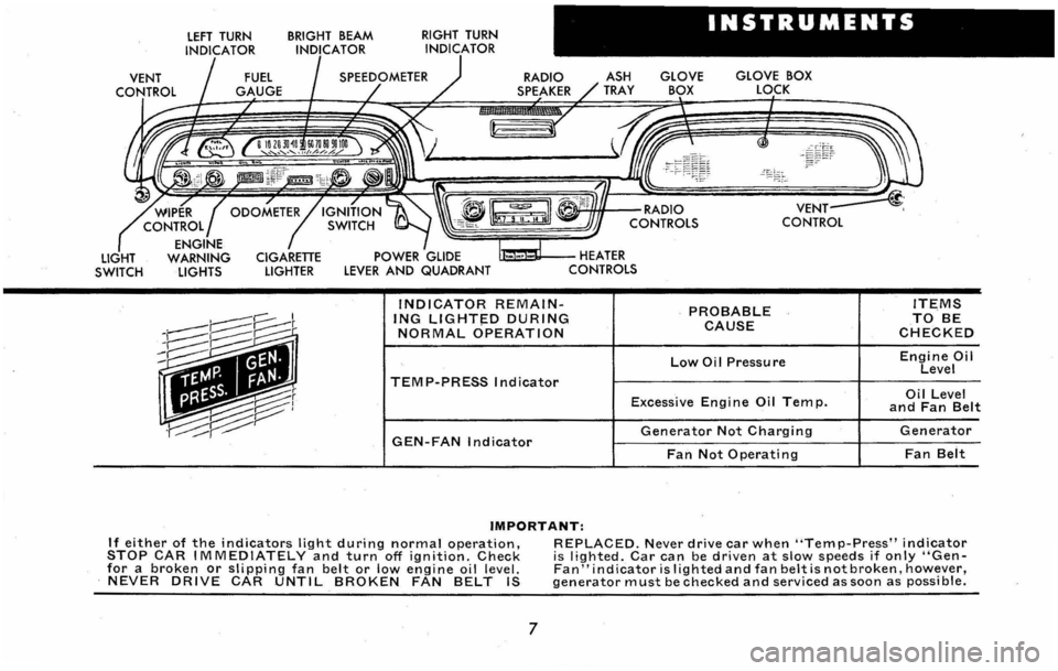
"TEMP-PRESS" AND "GEN-FAN" INDICATORS
These indicators are extremely important since they
provide a constant check on the operating condition of
the air cooled engine and the generator of your Corvair.
Both
indicator lights should light with the ignition switch
"ON" and before starting the engine. Indicator lights
will go out shortly after engine is, started and during
normal operation of the car. Flickering of the "Gen-Fan"
light while engine is idling is a normal condition.
Engine cooling depends on operation of the fan
driven by the Gen-Fan belt. A broken or slipping fan
belt will cause the Gen-Fan indicator to remain lighted
during normal operation and continued engine opera
tion can result in serious damage.
Page 10 of 38
LIGHT SWITCH
LEFT TURN
INDICATOR BRIGHT BEAM INDICATOR RIGHT
TURN
INDICATOR
INSTRUMENTS
RADIO SPEAKER GLOVE BOX
LOCK
~~"-fHIf--RADIO
~~~~~~~&J CONTROLS
U:a~II---HEATER CONTROLS
INDICATOR REMAINING LlGHT~D DURING NORMAL OPERATION
TEMP-PRESS Indicator
PROBABLE CAUSE
Low Oil Pressure
Excessive Engi ne Oil Tem p.
GEN-FAN Indicator Generator Not Charging
Fan Not Operating
IMPORTANT:
ITEMS TO BE CHECKED
Engine Oil Level
Oil Level and Fan Belt
Generator
Fan Belt
If either of the indicators light during normal operation, STOP CAR IMMEDIATELY and turn off ignition. Check for a broken or slipping fan belt or low engine oil level. NEVER DRIVE CAR UNTIL BROKEN FAN BELT IS
REPLACED. Never drive car when "Temp-Press" indicator i s lighted. Car can be driven at slow speeds if only "GenFan" indicator is I ighted and fan belt is not broken, however, generator must be checked and serviced as soon as possi ble.
7
Page 11 of 38
CONTROLS
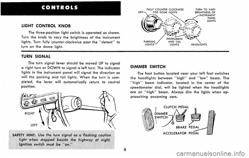
LIGHT CONTROL KNOB
The three-position light switch is operated as shown.
Turn the
knob to vary the brightness of the instrument
lights. Turn fully counter-clockwise past the "detent" to
turn on the dome light.
TURN SIGNAL
The turn signal lever should be moved UP to signal
a right turn or DOWN to signal a left turn. The indicator
lights in the instrument panel will signal the direction as
will the parking and tail lights. When the turn is com
pleted, the lever will automatically return to neutral
position.
8
FULLY COUNTER CLOCKWISE TURN TO VARY OFF@ORDOMELIGHTSBRIGHTNESSOF ~ ~ /INSTRUMENT ___ -." , PANEL
~~~
/,;----;; .... , ~ LIGHTS J -1'-I' ...... ' // ..-.... ~, /)~/,.~ .. ·,' ~ /1/ -' I II I" J/::::,'/·~"·I;'·""\ 1\1-~.P~ ~ \11 I" I'
/
-'-"'~\\ ,,/ ~ ... "., ~~-, ..... '1' ~~ .... "-'--INSTRUMENT ~-""-PARKING AND TAIL "-LIGHTS LIGHTS HEADLIGHTS
DIMMER SWITCH
The foot button located near your left foot switches
the
headlights between "high" and "low" beam. The
"high" beam indicator, located in the center of the
speedometer dial, will be lighted when the headlights
are on "high" beam. Always dim the lights when ap
proaching oncoming cars.
. I CLUTCH PEDAL
,,~~:U
Page 14 of 38
KEYS AND LOCKS
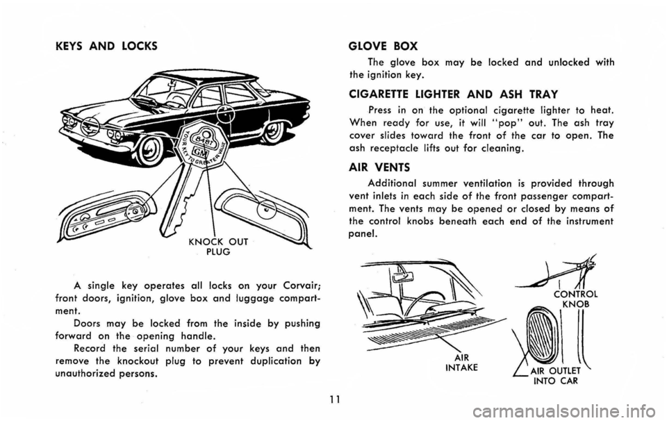
A single key operates all locks on your Corvair;
front doors, ignition, glove box and luggage compart
ment. Doors
may be locked from the inside by pushing
forward on the opening handle.
Record the serial number of your keys and then
remove the
knockout plug to prevent duplication by
unauthorized persons.
11
GLOVE BOX
The glove box may be locked and unlocked with
the ignition key.
CIGARETTE LIGHTER AND ASH TRAY
Press in on the optional cigarette lighter to heat.
When ready for use, it will .. pop" out. The ash tray
cover slides toward the front of the car to open. The
ash
receptacle lifts out for cleaning.
AIR VENTS
Additional summer ventilation is provided through
vent inlets in each side of the front passenger compart
ment. The vents may be opened or closed by means of
the control knobs beneath each end of the instrument
panel.
AIR INTAKE
INTO CAR
Page 20 of 38
ure up to U. S. standards, it is desirable to' obtain
detailed information as to availability of fuels in a given
area and service and adjustments n~cessary to adapt
your car to the fuels available. Such information may be
obtained by writing:
General Motors Overseas Operations
Service Department, Room 9-164
General Motors Building
Detroit 2, Michigan
Include with your request the area to which you
plan to take your car and the vehicle type and serial
number.
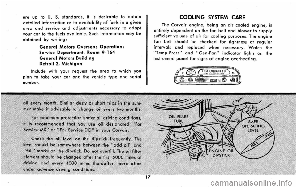
COOLING SYSTEM CARE
The Corvair engine, being an air cooled engine, is
entirely dependent on the fan belt and blower to supply
sufficient volume of air for cooling purposes. The engine
fan belt should be checked for tightness at regular
intervals and replaced when necessary. Watch the
"Temp-Press" and "Gen-Fan" indicator lights on the
instrument panel for signs of engine overheating.
OIiIOJl~ll!I[olrolin! ...... ~'-~ ............ ,'.,./ .. / ... A/
Page 23 of 38
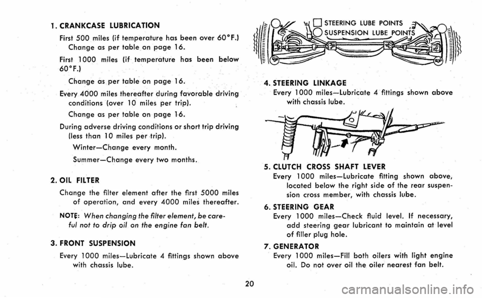
1. CRANKCASE LUBRICATION
First 500 miles (if temperature has been over 60° F.I
Change as per table, on page 16.
First 1000 miles (if-temperature has been below
60°F.1
Change as per table on page 16.
Every 4000 miles thereafte.r during favorab·le driving
conditions (over 10 miles per trip).
Change as per table on page 16.
During adverse driving conditions or short trip driving
(less
than 10 miles per trip).
Winter-Change every month.
Summer-Change every two months.
2. OIL FILTER
Change the filter element after the first 5000 miles
of operation, and every 4000 miles thereafter.
NOT~: When changing the filter element, be care
ful not to drip oil on the engine fan belt.
3. FRONT SUSPENSION
Every 1000 miles-lubricate 4 fittings shown above
with chassis lube.
20
4. STEERING LINKAGE
Every 1000 miles-lubricate 4 fittings shown above
with chassis lube.
5. CLUTCH CROSS SHAFT LEVER
Every 1000 miles-lubricate fitting shown above,
located below the right side of the rear suspen
sion cross member, with chassis lube.
6. STEERING GEAR
Every 1000 miles-Check fluid level. If necessary,
add steering gear lubricant to maintain at level
of filler plug hole.
7. GENERATOR
Every 1000 miles-Fill both oilers with light engine
oil. Do not over oil the oiler nearest fan belt.
Page 24 of 38
8. DISTRIBUTOR
Every 1000 miles-Fill hinged cap oiler with light
engine. oil.
Every 5000 miles-Apply small drop of light engine
oil to breaker lever pivot.
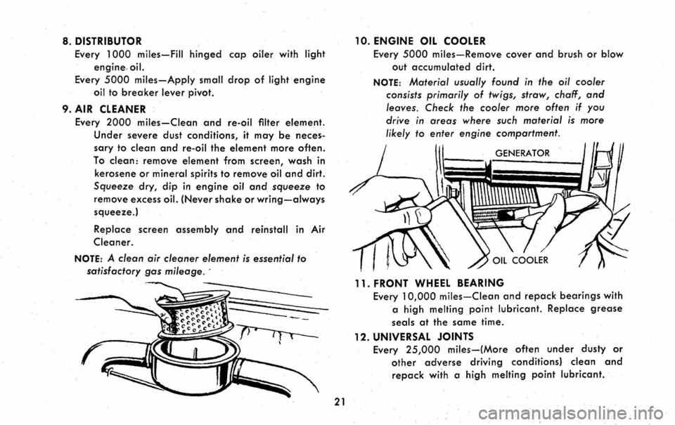
9. AIR CLEANER
Every 2000 miles-Clean .and re-oil filter element.
Under severe dust conditions, it may be neces
sary to clean and re-oil the element more often.
To clean: remove element from screen, wash in
kerosene
or mineral spirits to remove oil and dirt.
Squeeze dry, dip in engine oil and squeeze to
remove excess oiL (Never shake or wring-always
squeeze.)
Replace screen assembly and reinstall in Air
Cleaner.
NOTE: A clean air cleaner element is essential to
satisfactory gas mileage. -
21
10. ENGINE OIL COOLER
Every 5000 miles-Remove cover and brush or blow
out accumulated dirt.
NOTE: Material usually found in the oil cooler
consists primarily
of twigs, straw, chaff, and
leaves. Check the cooler more often if you
drive
in areas where such material is more
likely to enter engine compartment.
GENERATOR
11. FRONT WHEEL BEARING
Every 10,000 miles-Clean and repack bearings with
a high melting point lubricant. Replace grease
seals at the same time.
12. UNIVERSAL JOINTS
Every 25,000 miles-(More often under dusty or
other adverse driving conditions} clean and
repack with a high melting point lubricant.
Page 32 of 38
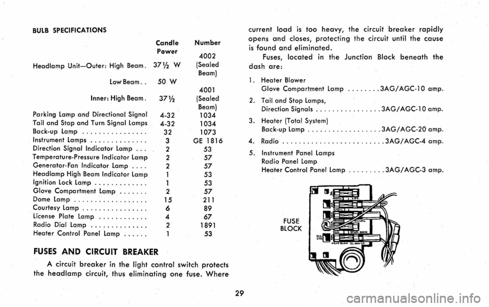
BULB SPECIFICATIONS Candle Power
Headlamp Unit-Outer: High Beam. 37 V2 W
Low Beam. . 50 W
Inner: High Beam.
Parking
Lamp and Directional Signal
Tail and Stop and Turn Signal Lamps
Back -up Lamp .... ....... .... .
Instrument Lamps ............. .
Direction
Signal Indicator Lamp .. .
Temperature-Pressure Indicator
Lamp
Generator-Fan Indicator Lamp ....
Headlamp High Beam Indicator Lamp
Ignition Lock Lamp ............ .
Glove Compartment
Lamp .... .. .
Dome Lamp ............. .. .. .
Courtesy
Lamp . .............. .
License Plate Lamp ........... .
Radio Dial
Lamp ............. .
Heater Control
Panel Lamp ..... .
FUSES AND CIRCUIT BREAKER
37%
4-32
4-32
32
3 2
2
2
1
1
2 15
6 4
2
1
Number
4002
(Sealed
Beam)
4001
(Sealed
Beam)
1034
1034 1073
GE 1816
53
57
57
53 53
57 211
89
67 1891
53
A
circuit breaker in the light control switch protects
the headlamp circuit, thus eliminating one fuse. Where
29
current load is too heavy, the circuit breaker rapidly
opens and closes, protecting the circuit until the cause
is found and eliminated.
Fuses,
located in the Junction Block beneath the
dash are:
1 . Heate r Blower
Glove Compartment
Lamp ........ 3AG/ AGC-l 0 amp.
2. Tail and Stop Lamps,
Direct ion Signals ................ 3AG/ AGC-l 0 amp ..
l. Heater (Total System)
Back-up Lamp . ........ ......... lAG/ AGC-20 amp .
4. Radio ..
......... ...... ........ lAG/ AGC-4 amp.
5. Instrument
Panel Lamps
Radio Panel Lamp
Heater Control Panel Lamp ... ...... 3AG/ AGC-3 amp.
FUSE BLOCK
Page 33 of 38
INDEX
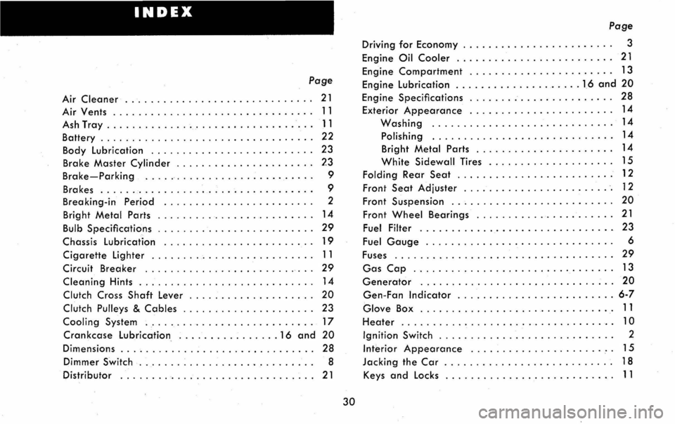
Page
Air Cleaner .............. , . ............ .. 21
Air Vents ............................... .
Ash Tray
............ .................... .
Battery ................................. .
Body
lubrication ......... . ............... .
Brake
Master Cylinder ..................... .
Brake-Parking .......................... .
Brakes
........ .. ............. .. ........ .
Breaking-in
Period . ........ .. ........... . .
11
11
22
23
?3
9
9
2
Bright Metal Parts . .............. .......... 14
Bulb Specifications .................... .... , 29
Chassis lubrication ................... ..... 19
Cigarette Lighter .......................... 11
Circuit Breaker ......... . ................. 29
Cleaning Hints . . . . . . . . . . . . . . . . . . . . . . . . . . .. 14
Clutch Cross Shaft lever ................... , 20
Clutch Pulleys & Cables .. . . . . . . . . . . . . . . . . . .. 23
Cooling System ........................... 17
Crankcase lubrication ................ 16 and 20
Dimensions .............................. . 28
Dimmer Switch ... ........................ . 8
Distributor .............................. . 21
30
Page
Driving for Economy . . . . . . . . . . . . . . . . . . . . . . .. 3
Engine Oil Cooler ............. .......... . . 21
Engine
Compartment ....................... 13
Engine lubrication .................... 16 and 20
Engine Specifications . . . . . . . . . . . . . . . . . . . . . .. 28
Exterior Appearance ....................... 14
Washing ............................. 14
Polishing ........ ..................... 14
Bright Metal Parts . . . . . . . . . . . . . . . . . . . . .. 14
White Sidewall Tires .................... 15
Folding Rear Seat . . . . . . . . . . . . . . . . . . . . . . . .. 12
Front Seat Adjuster ........................ 12
Front Suspension ......... ........ ......... 20
Front Wheel Bearings ............ .......... 21
Fuel Filter ............. .. ................ 23
Fuel Gauge . . . . . . . . . . . . . . . . . . . . . . . . . . . . .. 6
Fuses ..
................. ................ 29
Gas Cap ........ ........................ 13
Generator ............................... 20
Gen-Fan Indicator ......................... 6-7
Glove Box ......... .... ............... . ' .' 11
Heater .. . . . . . . . . . . . . . . . . . . . . . . . . . . . . . . .. 10
Ignition Switch . . . . . . . . . . . . . . . . . . . . . . . . . . .. 2
Interior Appearance ............... ...... .'. 15
Jacking the Car . . . . . . . . . . . . . . . . . . . . . . . . . .. 1 8
Keys
and Locks .... . . . . . . . . . . . . . . . . . . . . . .. 11
Page 34 of 38
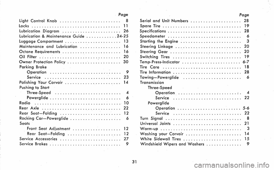
Page
Light Control Knob ........................ 8
locks ................................... 11
lubrication Diagram .. ....... . .......... .. . 26
lubrication & Maintenance Guide ............ 24-25
luggage Compartment . . . . . . . . . . . . . . . . . . . . .. 13
Maintenance and Lubrication ....... ......... 16
Octane Requirements . . . . . . . . . . . . . . . . . . . . . .. 16
Oil Filter ................................ 20
Owner Protection Policy ............ '. . . . . . . .. 30
Parking Brake
Operation ............................ 9
Service .
............................. 23
Polishing Your Corvair ...................... 14
Pushing to Start
Three-Speed ................. ......... 4
Powerglide . . . . . . . . . . . . . . . . . . . . . . . . . . . . 6
Radio
............. ..................... 10
Rear Axle .................. ............. 22
Rear Seat-Folding ....................... .
Rocking
Car-Powerglide . .................. .
Seats
12
6
Front Seat Adjustment . . . . . . . . . . . . . . . . . .. 12
Rea r Seat-Folding ..................... 1 2
Service Accessories
....................... .
Serv ice Brakes ........................... .
27
9
31
Page
Serial and Unit Numbers . . , ............... " 28
Spare Tire ..... . . . . . . . . . . . . . . . . . . . . . . . . .. 19
Specifications . . . . . . . . . . . . . . . . . . . . . . . . . . . .. 28
Speedometer ... .. ........ .......... ...... 6
Starting the Engine . .. . . . . . . . . . . . . . . . . . . . .. 3
Steering Linkage ............. ;............ 20
Steering Gear . . . . . . . . . . . . . . . . . . . . . . . . . . .. 20
Switching Tires ........................... 19
Temp-Press-Indicator ........ ............... 6-7
Tire Care ............................... 18
Tire Information . . . . . . . . . . . . . . . . . . . . . . . . . .. 28
Towing-Powerglide ....................... 6
Transmission
Three-Speed
Operation ................... ...... 4
Service ........................... 22
Powerglide
Operation .... . . . . . . . . . . . . . . . . . . . .. 5-6
Service .............. ............. 22
Turn Signal .............................. 8
Universal Joints ........................... 21
Warm-up. . . . . . . . . . . . . . . . . . . . . . . . . . . . . . . . 3
Washing your Corvair . . . . . . . . . . . . . . . . . . . . .. 14
White Sidewall Tires .... . . . . . . . . . . . . . . . . . .. 15
Windshield Wipers and Washers . . . . . . . . . . . . .. 9