pressure CHEVROLET CORVAIR 1965 2.G Owners Manual
[x] Cancel search | Manufacturer: CHEVROLET, Model Year: 1965, Model line: CORVAIR, Model: CHEVROLET CORVAIR 1965 2.GPages: 56, PDF Size: 22.29 MB
Page 8 of 56
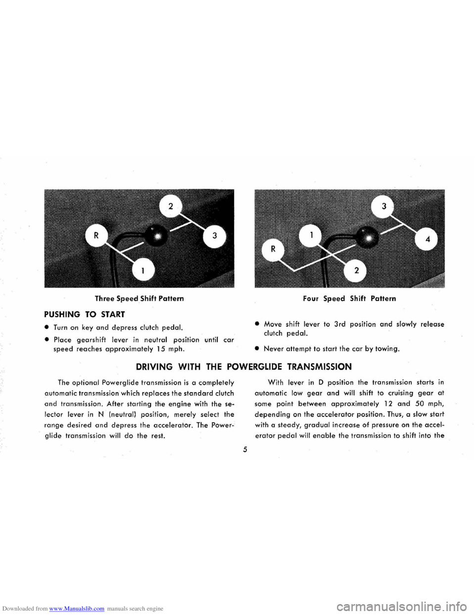
Downloaded from www.Manualslib.com manuals search engine Three Speed Shift Pattern
PUSHING TO START
• Turn on key and depress clutch pedal.
• Place gearshift lever in neutral position until car
speed reaches approximately 15 mph.
Four Speed Shift Pattern
• Move shift lever to 3rd position and slowly release
clutch pedal.
• Never attempt to start the car by towing.
DRIVING WITH THE POWERGLIDE TRANSMISSION
The optional Powerglide transmission is a completely
automatic transmission which replaces the standard clutch
and transmission. After starting the engine with the se
lector lever in N (neutral) position, merely select the
range desired and depress the accelerator. The Power
glide transmission will do the rest.
5
With lever in D position the transmission starts in
automatic low gear and will shift to cruising gear at
some point between approximately 12 and 50 mph,
depending on the accelerator position. Thus, a slow start
with a steady, gradual increase of pressure on the accel
erator pedal will enable the transmission to shift into the
Page 22 of 56
Downloaded from www.Manualslib.com manuals search engine REAR DOORS
• Rear doors, on 4-door models are operated from the
outside by means of a push button door handle in the
same
manner as the front doors. No key lock is pro
vided On the outside of either rear door.
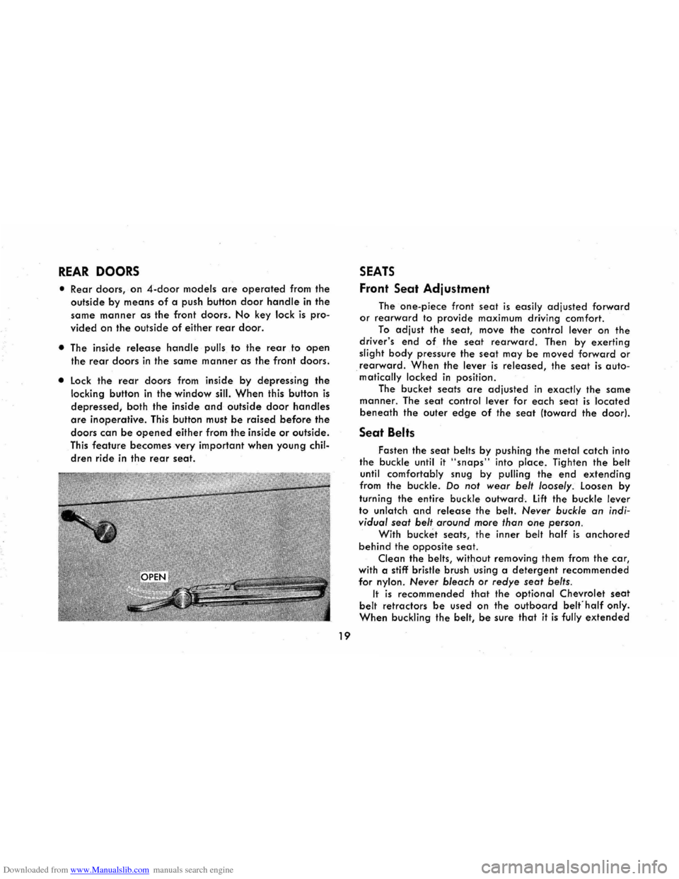
• The inside release handle pulls to the rear to open
the rear doors in the same manner as the front doors.
• lock the rear doors from inside by depressing the
locking button in the window sill. When this button is
depressed ,
both the inside and outside door handles
are inoperative. This button must be raised before the
doors can be opened either from the inside or outside.
This
feature becomes very important when young chil
dren ride in the rear seat.
19
SEATS
Front Seat Adjustment
The one-piece front seat is easily adjusted forward or rearward to provide maximum driving comfort.
To adjust the seat, move the control lever on the
driver's end of the seat rearward. Then by exerting
slight body pressure the seat may be moved forward or
rearward. When the lever is released, the seat is auto. matically locked in position.
The
bucket seats are adjusted in exactly the same
manner. The seat control lever for each seat is located
beneath the outer edge of the seat (toward the door).
Seat Belts
Fasten the seat belts by pushing the metal catch into
the buckle until it "snaps" into place, Tighten the belt
until comfortably snug by pulling the end extending
from the buckle. Do not wear belt loosely . loosen by
turning the entire buckle outward. lift the buckle lever
to unlatch and release the belt. Never buckle an indi
vidual seat belt around more than
one person .
With bucket seats, the inner belt half is anchored
behind the opposite seat.
Clean the belts, without removing them from the car,
with a stiff bristle brush using a detergent recommended
for nylon. Never bleach or redye seat belts .
It is recommended that the optional Chevrolet seat
belt retractors be used on the outboard belfhalf only.
When buckling the belt, be sure that it is fully extended
Page 25 of 56
Downloaded from www.Manualslib.com manuals search engine CORVAIR CORSA
The Corvair Corsa models are operated and main
tained as outlined for the regular Corvair. Additional
instrumentation and operating instructions peculiar to
Corsa models only are reviewed in the following pages.
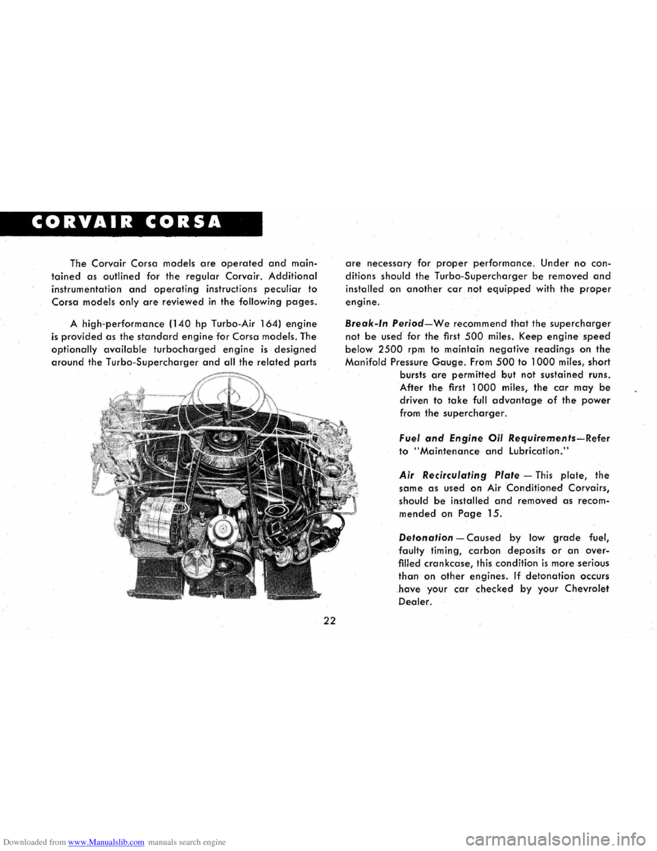
A high-performance (140 hp Turbo-Air 164) engine
is provided as the standard engine for Corsa models. The
optionally available turbocharged engine is designed
around the Turbo-Supercharger and all the related parts
22
are necessary for proper performance. Under no con
ditions should the Turbo-Supercharger be removed and
installed on another car not equipped with the proper
engine.
Break-In Period-We recommend that the supercharger
not be used for the first 500 miles. Keep engine speed
below 2500 rpm to maintain negative readings on the
Manifold Pressure Gauge. From 500 to 1000 miles, short
bursts
are permitted but not sustained runs.
After the first 1000 miles, the car may be
driven to take full advantage of the power
from the supercharger.
Fuel and Engine Oil Requirements~Refer
to "Maintenance and Lubrication."
Air Recirculating Plate -This plate, the
same as used on
Air Conditioned Corvairs,
should be installed and removed as recom
mended on Page 15.
Detonation -Caused by low grade fuel,
faulty timing, carbon deposits or an over
filled crankcase, this condition is more serious
than on other engines. If detonation occurs
have your car checked by your Chevrolet
Dealer.
Page 26 of 56
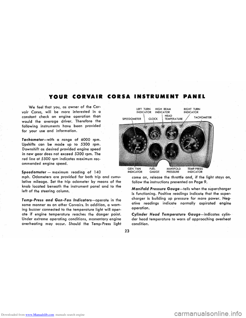
Downloaded from www.Manualslib.com manuals search engine YOUR CORVAIR CORSA INSTRUMENT PANEL
We feel that you, as owner of the Cor-
vair Corsa, will be more interested in a
constant check on
engine operation than
would the average driver. Therefore the
following instruments have been provided
for your use and information.
Tachometer-with a range of 6000 rpm.
Upshifts can
be made up to 5300 rpm.
Downshift as desired provided engine speed
in
new gear does not exceed 5300 rpm. The
red
line at 5500 rpm indicates maximum rec
ommencled
engine speed.
Speedometer -maximum reading of 140
mph. Odometers are provided for both trip and cumu
lative mileage. Set the trip odometer by means of the
knob located beneath the instrument panel and to the
left of the steering column.
Temp-Press and Gen-Fan Indicators-operate in the
same
manner as on other Corvairs. In addition, a warn
ing buzzer connected to the temperature light will oper
ate if engine temperature reaches the danger point.
Under extreme operating conditions, momentary engine
overheating may occur. Should the Temp-Press light
23
lEFT TURN HIGH BEAM INDICATOR INDICATOR
GAUGE PRESSURE
RIGHT TURN INDICATOR
come on, release the throttle and, if the light stays on,
follow the instructions presented on Page 9 .
Manifold Pressure Gauge-tells when the supercharger
is functioning. Positive readings indicate that the super
charger is building up pressure for more power. Neg
ative readings indicate normally aspirated engine
operation.
Cylinder Head Temperature Gauge-indicates cylin
der head temperature to warn of approaching overheat
condition.
Page 37 of 56
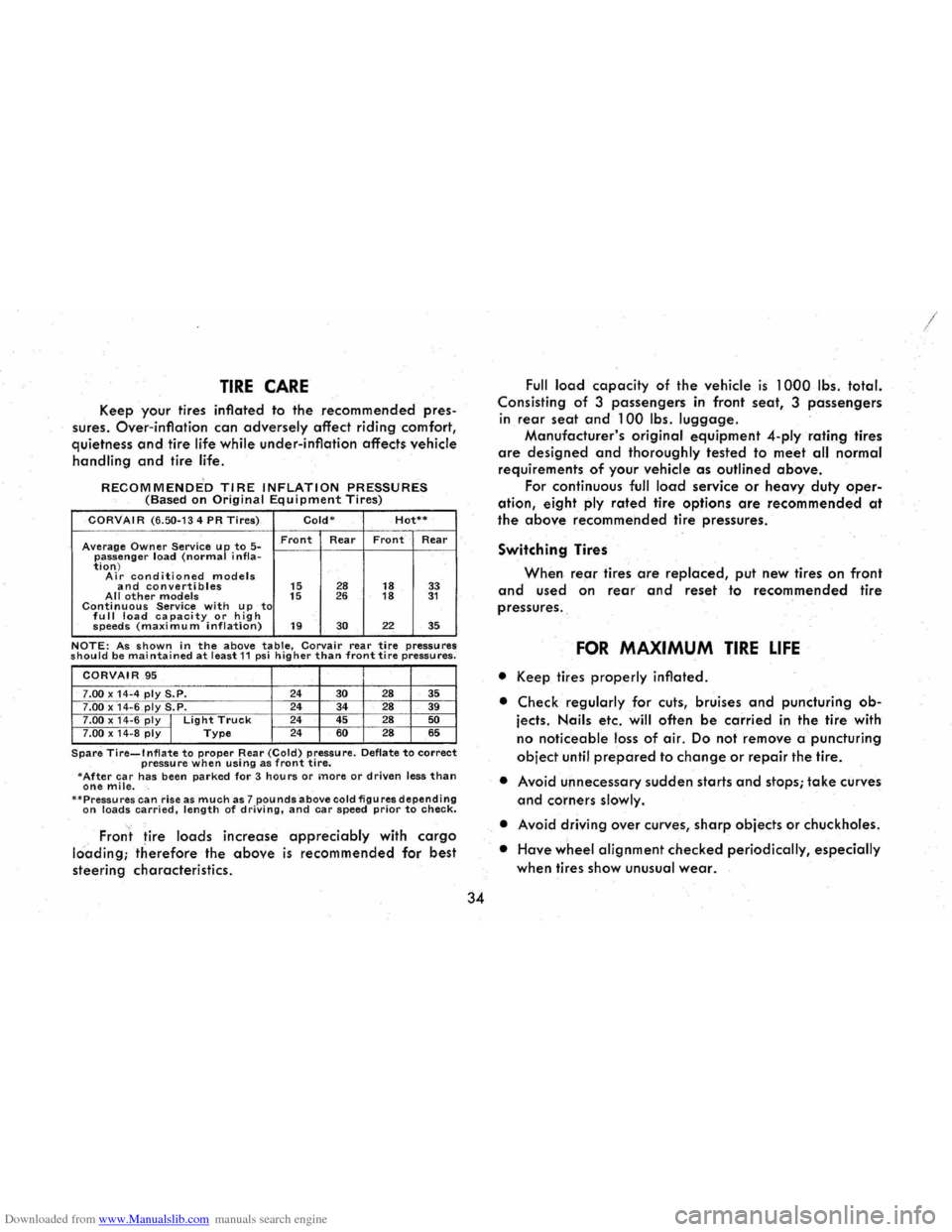
Downloaded from www.Manualslib.com manuals search engine TIRE CARE
Keep your tires inflated to the recommended pres
sures.
Over-inflation can adversely affect riding comfort,
quietness and tire life while under-inflation affects vehicle
handling and tire life.
RECOMMENDED TIRE INFLATION PRESSURES (Based on Original Equipment Tires)
CORVAIR (6.50-134 PR Tires) Cold-Hot**
Average Owner Service up to 5-Front Rear Front Rear
passenger load (normal i nfla-tion) Air conditioned models and convertibles 15 28 18 33 All other models 15 26 18 31 Continuous Service with up to fu II load ca pacity or h ig h speeds (maximu m inflation) 19 30 22 35
NOTE: As shown in the above table, Corvair rear tire pressures should be maintained at least 11 psi higher than front tire pressures;
CORVAIR .95
7.00 x 14"4 ply S.P. 24 30 28 35 7.00 x 14-6 ply S.P. 24
34 28 39 7.00 x 14-6 ply I Light Truck 24
45 28 50
7 .00 x 14 -8 ply I Type 24 60 28 65
Spare Tire...,.lnflate to proper Rear (Cold) pressure. Deflate to correct pressure when using as front tire. -After car has been parked for 3 hours or more or driven less than one mile. --Pressures can riseas much as 7 pounds above cold figures depending on loads carried, length of driving, and car speed prior to check.
, Fron t tire loads increase appreciably with cargo
lci'ading; therefore the above is recommended for best
steering characteristics.
34
Full load capacity of the vehicle is 1 OOOlbs. total.
Consisting of 3 passengers in front seat, 3 passengers
in
rear seat and 100 Ibs . luggage.
Manufacturer's original equipment 4-plyrating tires
are designed and thoroughly tested to meet all normal
requirements of your vehicle as outlined above.
For continuous full load service or heavy duty oper
ation, eight ply rated tire options are recommended at
the above recommended tire pressures.
Switching Tires
When rear tires are replaced, put new tires on front
and used on rear and reset to recommended tire
pressures. ,
FOR MAXIMUM TIRE LIFE
• Ke.ep tires properly inflated.
• Check regularly for cuts, bruises and puncturing ob
jects. Nails etc. will often be carried in the tire with
no noticeable loss of air. Do not remove a puncturing
object until prepared to change or repair the tire.
• Avoid unnecessary sudden starts and stops; take curves
and corners slowly.
•
Avoid driving over curves, sharp objects or chuckholes.
•
Have wheel alignment checked periodically, especially
when tires show unusual wear.
Page 53 of 56
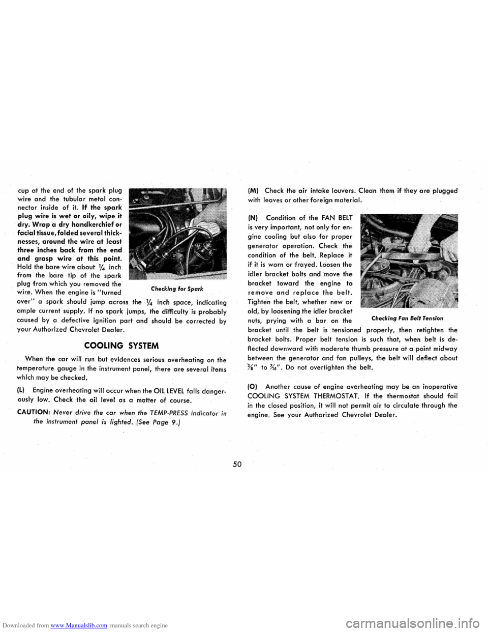
Downloaded from www.Manualslib.com manuals search engine cup at the end of the spark plug
wire
and the tubular metal con
nector inside of it. If the spark
plug wire is wet or oily, wipe it
dry. Wrap a dry handkerchief or
facial tissue, folded several thick
nesses, around the wire at least
three inches back from the end
and grasp wire at this point. Hold the bare wire about 1,4 inch
from the.
bare tip of the spark
plug from which you removed the
wir,e. When the engine is "turned Checking 'or Spark
over" a spark should jump across the 1,4 inch space, indicating
ample current supply. If no spark jumps, the difficulty is probably
caused by a defective ignition part and should be corrected by
your Authorized Chevrolet
Dealer.
COOLING SYSTEM
When the car will run but evidences serious overheating on the
temperature gauge in the instrument panel, there are several items
which may
be checked.
(L) Engine overheating will occur when the OIL LEVEL falls danger
ouslylow. Check the oil level as a malter of course.
CAUTION: Never drive the car when the TEMP-PRESS indicator in
the instrument panel is lighted. (See Page 9.)
50
(M) Check the air intake louvers . Clean them if they are plugged
with leaves or other foreign material.
(N) Condition of the FAN BELT
is very important, not only for en
gine cooling but
also for proper
generator operation. Check the
condit ion of the belt. Replace
it
if it is worn or frayed. Loosen the
idler
bracket bolts and move the
bracket toward the engine to
remove and replace the belt.
Tighten the belt, whether new or
old, by loosening the idler bracket nuts, prying with a bar on the Checking Fan Bel' Tension
bracket until the belt is tensioned properly, then retighten the
bracket bolts. Proper belt tension is such that, when belt is de
flected downward with moderate thumb pressure at a point midway
between the
generator and fan pulleys, the belt will deflect about
%" to X6". Do not overtighten the belt.
(0) Another cause of engine overheating may be an inoperative
COOLING SYSTEM THERMOSTAT. If the thermostat should fail
i n the closed position, it will not permit
air to circulate through the
engine. See your Authorized Chevrolet Dealer.
Page 55 of 56
Downloaded from www.Manualslib.com manuals search engine Page
luggage Compartment . . . . . . . . . . . . . . . . . . . . .. 21
Maintenance and lubrication (Periodic) ........ 37
Manifold Pressure Gauge ................... 23
Octane Requirements ....................... 32.
Oil Filter ................................. 37
Parking Brake
Operation ........................... 12
Service
..... ......................... 40
Polishing Your Corvair . . . . . . . . . . . . . . . . . . . . .. 30
Positraction Axle .......................... 7
Pushing to
Start
Manual Transmission ............. .... .. 5
Powerglide . . . . . . . . . . . . . . . . . . . . . . . . .
.. 6
Radios
................................ 16
Rear Axle ............................... 42
Rocking Car-Powerglide . . . . . . . . .. . . . . . . . . .. 7
Seats
......................... " .... 19 & 28
Front Seat Adjustment . . . . . . . . . . . . .. 19 & 28
Rear
Seat-Folding .................... 20
Second Seat . . . . . . . . . . . . . . . . . . . . . . . . .. 29
Service Brakes ............. . . . . . . . . . . . . . .. 12
Serial
and Unit Numbers . . . . . . . . . . . . . . . . . . .. 44
Spare Tire ............................... 35
Specifications . . . . . . . . . . . . .. . . . . . . . . . .. 44 & 45
52
Page
Speedometer ......................... 8 & 23
Starting the Engine ....... . . . . . . . . . . . . . . . . . 3
Steering
linkage .......................... 38
Steering Gear .... ' ................. ' .' . . . .. 37
Switching Tires .................•......... 34
Tachometer .............................. 23
Telescoping Steering Column ............... , 17
Temp-Press Indicator .................... 9 & 23
Tire
Care . . . . . . . . . . . . . . . . . . . . . . . . . . . . . . .. 34
Towing-Powerglide . . . . . . . . . . . . . . . . . . . . . . .. 7
Transmission Manual
Operation ..................... ,. 4-5
Service .......................... 41
Powerglide
Operation . . . . . . . . . . . . . . . . . . . . . .. 5-7
Service ........................ " 41
Trouble Shooting Guide . . . . . . . . . . . . . . . . . . . .. 47
Trouble Checks
lighting System
...................... .11
Turn Signal .............................. 11
Warm-up. . . . . . . . . . . . . . . . .. . . . . . . . .. . . . .. 4
Washing Your Corvair . . . . . . . . . . . . . . . . . . . . .. 30
White Sidewall Tires ....................... 31
Windshield Wipers and Washers ........... 13 & 25