steering wheel CHEVROLET CORVETTE 2013 6.G User Guide
[x] Cancel search | Manufacturer: CHEVROLET, Model Year: 2013, Model line: CORVETTE, Model: CHEVROLET CORVETTE 2013 6.GPages: 414, PDF Size: 6.97 MB
Page 77 of 414
Black plate (17,1)Chevrolet Corvette Owner Manual - 2013 - crc2 - 11/8/12
Seats and Restraints 3-17
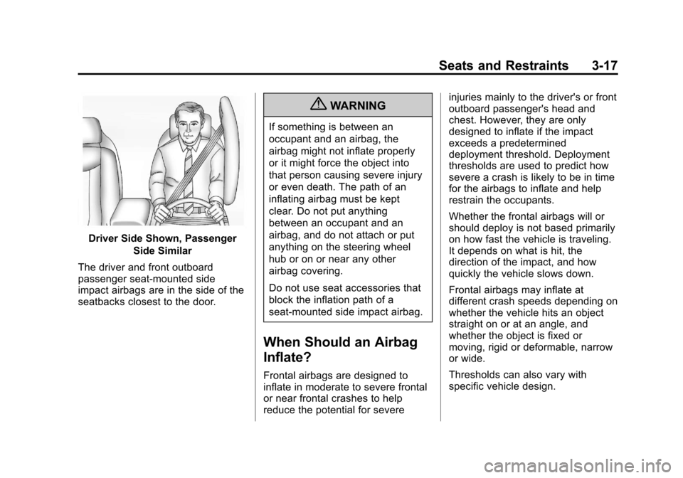
Driver Side Shown, PassengerSide Similar
The driver and front outboard
passenger seat-mounted side
impact airbags are in the side of the
seatbacks closest to the door.
{WARNING
If something is between an
occupant and an airbag, the
airbag might not inflate properly
or it might force the object into
that person causing severe injury
or even death. The path of an
inflating airbag must be kept
clear. Do not put anything
between an occupant and an
airbag, and do not attach or put
anything on the steering wheel
hub or on or near any other
airbag covering.
Do not use seat accessories that
block the inflation path of a
seat-mounted side impact airbag.
When Should an Airbag
Inflate?
Frontal airbags are designed to
inflate in moderate to severe frontal
or near frontal crashes to help
reduce the potential for severe injuries mainly to the driver's or front
outboard passenger's head and
chest. However, they are only
designed to inflate if the impact
exceeds a predetermined
deployment threshold. Deployment
thresholds are used to predict how
severe a crash is likely to be in time
for the airbags to inflate and help
restrain the occupants.
Whether the frontal airbags will or
should deploy is not based primarily
on how fast the vehicle is traveling.
It depends on what is hit, the
direction of the impact, and how
quickly the vehicle slows down.
Frontal airbags may inflate at
different crash speeds depending on
whether the vehicle hits an object
straight on or at an angle, and
whether the object is fixed or
moving, rigid or deformable, narrow
or wide.
Thresholds can also vary with
specific vehicle design.
Page 78 of 414
Black plate (18,1)Chevrolet Corvette Owner Manual - 2013 - crc2 - 11/8/12
3-18 Seats and Restraints
Frontal airbags are not intended to
inflate during vehicle rollovers, rear
impacts, or in many side impacts.
In addition, the vehicle has
dual-stage frontal airbags.
Dual-stage airbags adjust the
restraint according to crash severity.
The vehicle has electronic frontal
sensors, which help the sensing
system distinguish between a
moderate frontal impact and a more
severe frontal impact. For moderate
frontal impacts, dual-stage airbags
inflate at a level less than full
deployment. For more severe frontal
impacts, full deployment occurs.
Depending on the model, the
vehicle may have one or two seat
position sensors. The seat position
sensor(s) enable the sensing
system to monitor the position of the
driver seat (all models) and the front
outboard passenger seat
(all models). Seat position sensor(s)
provide information that is used in
determining whether the airbags
should inflate at a reduced or full
level.The vehicle has seat-mounted side
impact airbags. See
Airbag System
on page 3‑14. Seat-mounted side
impact airbags are intended to
inflate in moderate to severe side
crashes, depending on the location
of the impact. Seat-mounted side
impact airbags will inflate if the
crash severity is above the system's
designed threshold level. The
threshold level can vary with
specific vehicle design.
Seat-mounted side impact airbags
are not intended to inflate in frontal
impacts, near-frontal impacts,
rollovers, or rear impacts.
A seat-mounted side impact airbag
is intended to inflate on the side of
the vehicle that is struck.
In any particular crash, no one can
say whether an airbag should have
inflated simply because of the
vehicle damage or repair costs.What Makes an Airbag
Inflate?
In a deployment event, the sensing
system sends an electrical signal
triggering a release of gas from the
inflator. Gas from the inflator fills the
airbag causing the bag to break out
of the cover. The inflator, the airbag,
and related hardware are all part of
the airbag module.
For airbag locations, see Where Are
the Airbags? on page 3‑16.
How Does an Airbag
Restrain?
In moderate to severe frontal or
near frontal collisions, even belted
occupants can contact the steering
wheel or the instrument panel. In
moderate to severe side collisions,
even belted occupants can contact
the inside of the vehicle.
Page 85 of 414
Black plate (25,1)Chevrolet Corvette Owner Manual - 2013 - crc2 - 11/8/12
Seats and Restraints 3-25
Adding Equipment to the
Airbag-Equipped Vehicle
Adding accessories that change the
vehicle's frame, bumper system,
height, front end or side sheet
metal, may keep the airbag system
from working properly. The
operation of the airbag system can
also be affected by changing or
moving any parts of the front seats,
safety belts, the airbag sensing and
diagnostic module, steering wheel,
instrument panel, inside rearview
mirror, front sensors, or airbag
wiring.
Your dealer and the service manual
have information about the location
of the airbag sensors, sensing and
diagnostic module, and airbag
wiring.
In addition, the vehicle has a
passenger sensing system for the
front outboard passenger position,
which includes sensors that are part
of the passenger seat. The
passenger sensing system may not
operate properly if the original seattrim is replaced with non-GM
covers, upholstery or trim, or with
GM covers, upholstery or trim
designed for a different vehicle. Any
object, such as an aftermarket seat
heater or a comfort enhancing pad
or device, installed under or on top
of the seat fabric, could also
interfere with the operation of the
passenger sensing system. This
could either prevent proper
deployment of the passenger
airbag(s) or prevent the passenger
sensing system from properly
turning off the passenger airbag(s).
See
Passenger Sensing System on
page 3‑20.
If you have to modify your vehicle
because you have a disability and
have questions about whether the
modifications will affect the vehicle's
airbag system, or if you have
questions about whether the airbag
system will be affected if the vehicle
is modified for any other reason, call Customer Assistance. See
Customer Assistance Offices (U.S.
and Canada) on page 13‑5
or
Customer Assistance Offices
(Mexico) on page 13‑5.
Airbag System Check
The airbag system does not need
regularly scheduled maintenance or
replacement. Make sure the airbag
readiness light is working. See
Airbag Readiness Light on
page 5‑16.
Notice: If an airbag covering is
damaged, opened, or broken, the
airbag may not work properly. Do
not open or break the airbag
coverings. If there are any
opened or broken airbag covers,
have the airbag covering and/or
airbag module replaced. For the
location of the airbags, see
Where Are the Airbags? on
page 3‑16. See your dealer for
service.
Page 105 of 414
Black plate (1,1)Chevrolet Corvette Owner Manual - 2013 - crc2 - 11/8/12
Instruments and Controls 5-1
Instruments and
Controls
Controls
Steering Wheel Adjustment . . . 5-2
Steering Wheel Controls . . . . . . 5-3
Horn . . . . . . . . . . . . . . . . . . . . . . . . . . 5-4
Windshield Wiper/Washer . . . . . 5-4
Compass . . . . . . . . . . . . . . . . . . . . . 5-5
Clock . . . . . . . . . . . . . . . . . . . . . . . . . 5-6
Power Outlets . . . . . . . . . . . . . . . . . 5-6
Cigarette Lighter . . . . . . . . . . . . . . 5-7
Ashtrays . . . . . . . . . . . . . . . . . . . . . . 5-7
Warning Lights, Gauges, and
Indicators
Warning Lights, Gauges, andIndicators . . . . . . . . . . . . . . . . . . . . 5-8
Instrument Cluster . . . . . . . . . . . . 5-9
Speedometer . . . . . . . . . . . . . . . . 5-12
Odometer . . . . . . . . . . . . . . . . . . . . 5-12
Tachometer . . . . . . . . . . . . . . . . . . 5-12
Fuel Gauge . . . . . . . . . . . . . . . . . . 5-12
Boost Gauge (ZR1) . . . . . . . . . . 5-13
Engine Oil Pressure Gauge . . . . . . . . . . . . . . . . . . . . . . 5-14 Engine Coolant Temperature
Gauge . . . . . . . . . . . . . . . . . . . . . . 5-15
Voltmeter Gauge . . . . . . . . . . . . . 5-16
Safety Belt Reminders . . . . . . . 5-16
Airbag Readiness Light . . . . . . 5-16
Passenger Airbag Status Indicator . . . . . . . . . . . . . . . . . . . . 5-17
Malfunction Indicator Lamp . . . . . . . . . . . . . 5-18
Brake System Warning Light . . . . . . . . . . . . . . . . . . . . . . . 5-20
Antilock Brake System (ABS) Warning Light . . . . . . . . . . . . . . 5-21
One-to-Four Shift Light (Manual Transmission) . . . . . 5-21
Traction Off Light . . . . . . . . . . . . 5-22
StabiliTrak
®OFF Light . . . . . . . 5-22
Active Handling System Light . . . . . . . . . . . . . . . . . . . . . . . 5-23
Tire Pressure Light . . . . . . . . . . 5-23
Security Light . . . . . . . . . . . . . . . . 5-24
High-Beam On Light . . . . . . . . . 5-24
Front Fog Lamp Light . . . . . . . . 5-24
Lamps On Reminder . . . . . . . . . 5-25
Information Displays
Driver Information Center (DIC) . . . . . . . . . . . . . . . 5-25
Head-Up Display (HUD) . . . . . 5-30
Vehicle Messages
Vehicle Messages . . . . . . . . . . . 5-34
Battery Voltage and Charging Messages . . . . . . . . . . . . . . . . . . 5-34
Brake System Messages . . . . 5-35
Convertible Top Messages . . . 5-36
Cruise Control Messages . . . . 5-37
Door Ajar Messages . . . . . . . . . 5-37
Engine Cooling System Messages . . . . . . . . . . . . . . . . . . 5-38
Engine Oil Messages . . . . . . . . 5-39
Engine Power Messages . . . . 5-39
Fuel System Messages . . . . . . 5-40
Key and Lock Messages . . . . . 5-40
Lamp Messages . . . . . . . . . . . . . 5-42
Ride Control System Messages . . . . . . . . . . . . . . . . . . 5-42
Safety Belt Messages . . . . . . . 5-46
Service Vehicle Messages . . . 5-47
Starting the Vehicle Messages . . . . . . . . . . . . . . . . . . 5-47
Tire Messages . . . . . . . . . . . . . . . 5-48
Transmission Messages . . . . . 5-50
Vehicle Reminder Messages . . . . . . . . . . . . . . . . . . 5-51
Washer Fluid Messages . . . . . 5-51
Vehicle Personalization
Vehicle Personalization . . . . . . 5-51
Page 106 of 414
Black plate (2,1)Chevrolet Corvette Owner Manual - 2013 - crc2 - 11/8/12
5-2 Instruments and Controls
Universal Remote System
Universal Remote System . . . 5-60
Universal Remote SystemProgramming . . . . . . . . . . . . . . . 5-60
Universal Remote System Operation . . . . . . . . . . . . . . . . . . 5-65Controls
Steering Wheel
Adjustment
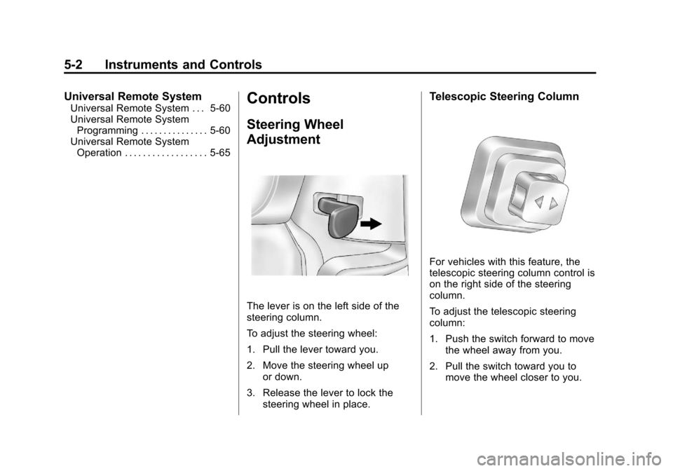
The lever is on the left side of the
steering column.
To adjust the steering wheel:
1. Pull the lever toward you.
2. Move the steering wheel up
or down.
3. Release the lever to lock the steering wheel in place.
Telescopic Steering Column
For vehicles with this feature, the
telescopic steering column control is
on the right side of the steering
column.
To adjust the telescopic steering
column:
1. Push the switch forward to movethe wheel away from you.
2. Pull the switch toward you to move the wheel closer to you.
Page 107 of 414
Black plate (3,1)Chevrolet Corvette Owner Manual - 2013 - crc2 - 11/8/12
Instruments and Controls 5-3
The telescopic steering column
position can be stored with your
memory settings. SeeMemory
Seats on page 3‑4.
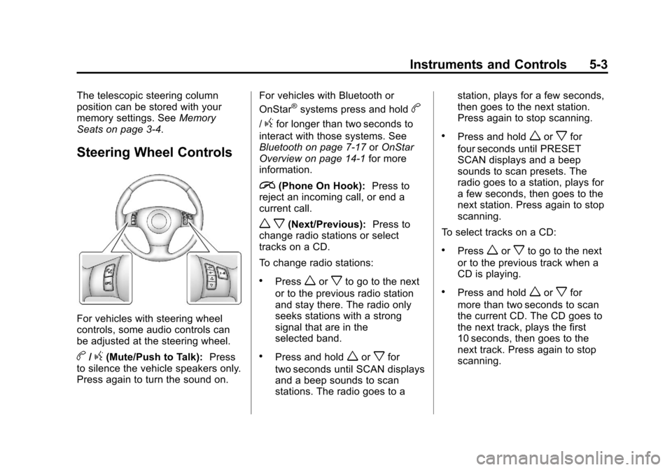
Steering Wheel Controls
For vehicles with steering wheel
controls, some audio controls can
be adjusted at the steering wheel.
b/g(Mute/Push to Talk): Press
to silence the vehicle speakers only.
Press again to turn the sound on. For vehicles with Bluetooth or
OnStar
®systems press and holdb
/gfor longer than two seconds to
interact with those systems. See
Bluetooth on page 7‑17 orOnStar
Overview on page 14‑1 for more
information.
i(Phone On Hook): Press to
reject an incoming call, or end a
current call.
w x(Next/Previous): Press to
change radio stations or select
tracks on a CD.
To change radio stations:
.Pressworxto go to the next
or to the previous radio station
and stay there. The radio only
seeks stations with a strong
signal that are in the
selected band.
.Press and holdworxfor
two seconds until SCAN displays
and a beep sounds to scan
stations. The radio goes to a station, plays for a few seconds,
then goes to the next station.
Press again to stop scanning.
.Press and holdworxfor
four seconds until PRESET
SCAN displays and a beep
sounds to scan presets. The
radio goes to a station, plays for
a few seconds, then goes to the
next station. Press again to stop
scanning.
To select tracks on a CD:
.Pressworxto go to the next
or to the previous track when a
CD is playing.
.Press and holdworxfor
more than two seconds to scan
the current CD. The CD goes to
the next track, plays the first
10 seconds, then goes to the
next track. Press again to stop
scanning.
Page 108 of 414
Black plate (4,1)Chevrolet Corvette Owner Manual - 2013 - crc2 - 11/8/12
5-4 Instruments and Controls
.Press and holdworxfor
more than four seconds to scan
all of the CDs loaded. The CD
goes to the next CD, plays the
first 10 seconds of each track,
then goes to the next CD. Press
again to stop scanning.
+
e−e(Volume): Press to
increase or to decrease the radio
volume.
1 to 6 (Preset Pushbuttons):
Press to play stations that are
programmed on the radio preset
pushbuttons.
Horn
Press near or on the horn symbols
on the steering wheel pad to sound
the horn.
Windshield Wiper/Washer
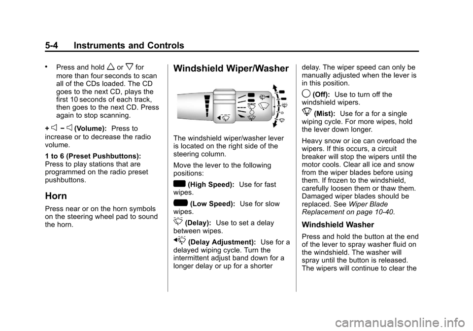
The windshield wiper/washer lever
is located on the right side of the
steering column.
Move the lever to the following
positions:
w(High Speed): Use for fast
wipes.
?(Low Speed): Use for slow
wipes.
3(Delay): Use to set a delay
between wipes.
x(Delay Adjustment): Use for a
delayed wiping cycle. Turn the
intermittent adjust band down for a
longer delay or up for a shorter delay. The wiper speed can only be
manually adjusted when the lever is
in this position.
9(Off):
Use to turn off the
windshield wipers.
8(Mist): Use for a for a single
wiping cycle. For more wipes, hold
the lever down longer.
Heavy snow or ice can overload the
wipers. If this occurs, a circuit
breaker will stop the wipers until the
motor cools. Clear all ice and snow
from the wiper blades before using
them. If frozen to the windshield,
carefully loosen them or thaw them.
Damaged wiper blades should be
replaced. See Wiper Blade
Replacement on page 10‑40.
Windshield Washer
Press and hold the button at the end
of the lever to spray washer fluid on
the windshield. The washer will
spray until the button is released.
The wipers will continue to clear the
Page 124 of 414
Black plate (20,1)Chevrolet Corvette Owner Manual - 2013 - crc2 - 11/8/12
5-20 Instruments and Controls
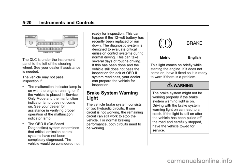
The DLC is under the instrument
panel to the left of the steering
wheel. See your dealer if assistance
is needed.
The vehicle may not pass
inspection if:
.The malfunction indicator lamp is
on with the engine running, or if
the vehicle is placed in Service
Only Mode and the malfunction
indicator lamp does not come
on. See your dealer for
assistance in verifying proper
operation of the malfunction
indicator lamp.
.The OBD II (On-Board
Diagnostics) system determines
that critical emission control
systems have not been
completely diagnosed. The
vehicle would be considered notready for inspection. This can
happen if the 12-volt battery has
recently been replaced or run
down. The diagnostic system is
designed to evaluate critical
emission control systems during
normal driving. This can take
several days of routine driving.
If this has been done and the
vehicle still does not pass the
inspection for lack of OBD II
system readiness, your dealer
can prepare the vehicle for
inspection.
Brake System Warning
Light
The vehicle brake system consists
of two hydraulic circuits. If one
circuit is not working, the remaining
circuit can still work to stop the
vehicle. For normal braking
performance, both circuits need to
be working.
MetricEnglish
This light comes on briefly while
starting the engine. If it does not
come on, have it fixed so it is ready
to warn if there is a problem.
{WARNING
The brake system might not be
working properly if the brake
system warning light is on.
Driving with the brake system
warning light on can lead to a
crash. If the light is still on after
the vehicle has been pulled off
the road and carefully stopped,
have the vehicle towed for
service.
Page 136 of 414
Black plate (32,1)Chevrolet Corvette Owner Manual - 2013 - crc2 - 11/8/12
5-32 Instruments and Controls
Within each mode, the display, can
be further customized by pressing
the PAGE button. Pressing this
button in each mode will turn off and
on the following:
.Street Mode—No tachometer,
circular tachometer, and linear
tachometer.
.Track Modes 1 and 2 —No
minor gauge, coolant
temperature, transmission oil
temperature (Automatic
Transmission only), engine oil
temperature, engine oil
pressure, and boost gauge.
While in Track Mode 1 or 2, the
maximum G value achieved
during the current ignition cycle
can be displayed by pressing
and holding the PAGE button.
The maximum G display will be
shown until the PAGE button is
released. The maximum G value
display will be identical to the
normal G value display,
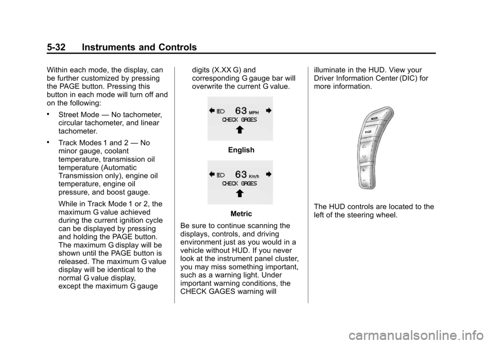
except the maximum G gauge digits (X.XX G) and
corresponding G gauge bar will
overwrite the current G value.English
Metric
Be sure to continue scanning the
displays, controls, and driving
environment just as you would in a
vehicle without HUD. If you never
look at the instrument panel cluster,
you may miss something important,
such as a warning light. Under
important warning conditions, the
CHECK GAGES warning will illuminate in the HUD. View your
Driver Information Center (DIC) for
more information.The HUD controls are located to the
left of the steering wheel.
Page 158 of 414
Black plate (54,1)Chevrolet Corvette Owner Manual - 2013 - crc2 - 11/8/12
5-54 Instruments and Controls
When the mode you want is
selected, press the OPTION button
to set your choice and advance to
the next personal option.
Auto Exit Recall:If your vehicle
has the memory package, you may
have this option. This option allows
the driver seat and telescopic
steering column, if your vehicle has
this feature, to automatically move
to the current driver's exit position
when one of the following occurs:
.The vehicle is turned off or in
Retained Accessory Power
(RAP) or accessory mode and
the driver door is opened.
.The vehicle is turned off or in
RAP and the unlock button on
the RKE transmitter is pressed.
In order for the Auto Exit Recall
feature to work on an automatic
transmission vehicle, the vehicle
must be in P (Park). On a manual
transmission vehicle, the parking
brake must be set. Press the OPTION button until
AUTO EXIT RECALL appears on
the display, then press the RESET
button to scroll through the following
modes:
.YES
.NO (default)
If you choose YES, when you turn
the ignition off and open the driver
door or press the unlock button on
the RKE transmitter, the seat and
the telescopic steering wheel, if your
vehicle has this feature, will return
to their stored exit positions for an
easy exit or an easy entrance when
returning to the vehicle.
The seat and steering wheel will
only return to the stored driving
position if you press the appropriate
memory button or activate the Auto
Memory Recall feature.
If you choose NO, this option will
turn off. When the mode you want is
selected, press the OPTION button
to set your choice and advance to
the next personal option.
Approach Lights:
This option
briefly turns on the parking lamps,
the high-beam headlamps, and the
back-up lamps during low light
periods when the RKE transmitter is
used to unlock the vehicle.
Press the OPTION button until
APPROACH LIGHTS appears on
the display, then press the RESET
button to scroll through the following
modes:
.OFF
.ON (default)
If you choose OFF, this option will
turn off.