CHEVROLET CORVETTE 2023 Owners Manual
Manufacturer: CHEVROLET, Model Year: 2023, Model line: CORVETTE, Model: CHEVROLET CORVETTE 2023Pages: 351, PDF Size: 6.28 MB
Page 181 of 351
Chevrolet Corvette Owner Manual (GMNA-Localizing-U.S./Canada/Mexico-
16287457) - 2023 - CRC - 3/10/22
180 Driving and Operating
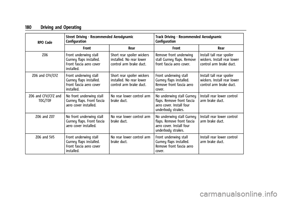
RPO CodeStreet Driving - Recommended Aerodynamic
Configuration
Track Driving - Recommended Aerodynamic
Configuration
Front RearFront Rear
Z06 Front underwing stall Gurney flaps installed.
Front fascia aero cover
installed. Short rear spoiler wickers
installed. No rear lower
control arm brake duct.
Remove front underwing
stall Gurney flaps. Remove
front fascia aero cover.Install tall rear spoiler
wickers. Install rear lower
control arm brake duct.
Z06 and CFV/CFZ Front underwing stall Gurney flaps installed.
Front fascia aero cover
installed. Short rear spoiler wickers
installed. No rear lower
control arm brake duct.
Front underwing stall
Gurney flaps installed.
Remove front fascia aero
cover.Install tall rear spoiler
wickers. Install rear lower
control arm brake duct.
Z06 and CFV/CFZ and T0G/T0F No front underwing stall
Gurney flaps. Front fascia
aero cover installed. No rear lower control arm
brake duct.
No underwing stall Gurney
flaps. Remove front fascia
aero cover. Install four
underbody strakes.Install rear lower control
arm brake duct.
Z06 and Z07 No front underwing stall Gurney flaps. Front fascia
aero cover installed. No rear lower control arm
brake duct.
No underwing stall Gurney
flaps. Remove front fascia
aero cover. Install four
underbody strakes.Install rear lower control
arm brake duct.
Z06 and 5V5 Front underwing stall Gurney flaps installed.
Front fascia aero cover
installed. No rear lower control arm
brake duct.
Front underwing stall
Gurney flaps installed.
Remove front fascia aero
cover.Install rear lower control
arm brake duct.
Page 182 of 351
Chevrolet Corvette Owner Manual (GMNA-Localizing-U.S./Canada/Mexico-
16287457) - 2023 - CRC - 3/10/22
Driving and Operating 181
Shock Spring Seat Adjustment
The front shocks, on vehicles without
hydraulic front lift and rear shocks, have
threaded spring seats that allow adjustment
of the preload on the coil springs. The
vehicle corner weights can be adjusted for
track use. If the vehicle trim height is
modified, it should be returned to normal
trim height before street use.
The spring seat can be adjusted
approximately 20 mm (0.8 in) up or down
from the nominal position. Each complete
turn of the spring seat will change the
vehicle height approximately 1.5 mm
(0.06 in). When adjusting the seat to the
upper limit, lift the dust boot and ensure
the seat does not thread off the center
support tube (stop adjustment when threads
no longer visible). When adjusting the seat
to the lower limit, leave approximately
10 mm (0.4 in) of thread visible for the
lower lock nut to have full thread
engagement.
The following procedure can be complex and
should only be performed by trained
personnel. See your dealer.To adjust the lower spring seat:
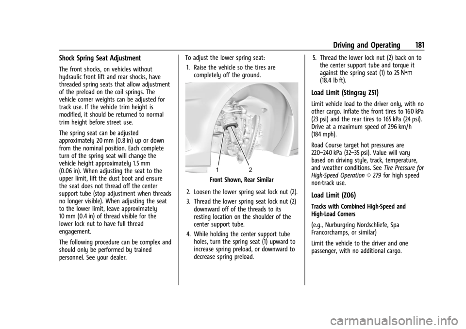
1. Raise the vehicle so the tires are completely off the ground.
Front Shown, Rear Similar
2. Loosen the lower spring seat lock nut (2).
3. Thread the lower spring seat lock nut (2) downward off of the threads to its
resting location on the shoulder of the
center support tube.
4. While holding the center support tube holes, turn the spring seat (1) upward to
increase spring preload, or downward to
decrease spring preload. 5. Thread the lower lock nut (2) back on to
the center support tube and torque it
against the spring seat (1) to 25 Y
(18.4 lb ft).
Load Limit (Stingray Z51)
Limit vehicle load to the driver only, with no
other cargo. Inflate the front tires to 160 kPa
(23 psi) and the rear tires to 165 kPa (24 psi).
Drive at a maximum speed of 296 km/h
(184 mph).
Road Course target hot pressures are
220–240 kPa (32–35 psi). Value will vary
based on driving style, track, temperature,
and weather conditions. See Tire Pressure for
High-Speed Operation 0279 for high speed
non-track use.
Load Limit (Z06)
Tracks with Combined High-Speed and
High-Load Corners
(e.g., Nurburgring Nordschliefe, Spa
Francorchamps, or similar)
Limit the vehicle to the driver and one
passenger, with no additional cargo.
Page 183 of 351
Chevrolet Corvette Owner Manual (GMNA-Localizing-U.S./Canada/Mexico-
16287457) - 2023 - CRC - 3/10/22
182 Driving and Operating
Cold Tire Pressure Requirement: Inflate tires
to no less than 210 kPa (30 psi) front and
rear, cold.
Hot Tire Pressure Target Range:
220–240 kPa (32-35 psi).
Road/Street Courses
(e.g., Virginia International Raceway, Road
Atlanta, or similar)
Limit the vehicle to the driver and one
passenger, with no additional cargo.
Cold Tire Pressure Requirement: Inflate tires
to no less than 165 kPa (24 psi) front and
rear, cold.
Hot Tire Pressure Target Range:
220 –240 kPa (32-35 psi).
See Tire Pressure for High-Speed Operation
0 279 for high speed non track use.
Wheel Alignment
Caution
Using these wheel alignment settings
may cause excessive tire wear. Only use
these wheel alignment settings for racing
(Continued)
Caution (Continued)
or competitive driving. Excessive tire wear
is not covered under the vehicle
warranty.
Caution
Do not use power tools when removing
or installing the fasteners. Damage to the
threads may occur. Use hand tools only,
and do not overtighten. Hand start the
fasteners to ensure that the threads do
not bind or cross thread.
The racing and competitive driving wheel
alignment settings should be set as
described here.
Stingray Z51
To achieve the track alignment specified
settings: 1. The upper control arm to body washers on all four corners must be moved from
between the body and the control arm
and relocated between the head of the
bolt and the control arm. 2. Adjust the lower control arm cam bolt
position to achieve the following
specifications:
Front (per corner)
.Caster: +8.0 degrees
.Camber: -3.0 degrees
.Toe (total): 0.1 degrees toe in
Rear (per corner)
.Caster: 0 degrees
.Camber: -2.5 degrees
.Toe (total): 0.1 degrees toe in
.Thrust Angle: 0 degrees
After track use, reinstall washers between
the body and the control arms. Reset to
factory alignment settings. See your dealer.
Z06 1. The upper control arm washers do not need to be removed for Z06.
2. Adjust the lower control arm cam bolt position to achieve the following
specifications:
Front (per corner)
.Caster: +8.0 degrees
.Camber: -2.0 degrees
.Toe (total): 0.1 degrees toe in
Page 184 of 351
Chevrolet Corvette Owner Manual (GMNA-Localizing-U.S./Canada/Mexico-
16287457) - 2023 - CRC - 3/10/22
Driving and Operating 183
Rear (per corner)
.Caster: 0 degrees
.Camber: -2.0 degrees
.Toe (total): 0.1 degrees toe in
.Thrust Angle: 0 degrees
Z06 with Z07 Performance Package Equipped
With Carbon Fiber Wheels (RPOs ROY
and ROZ)
When participating in Track Events or
Competitive Driving with these wheels, a
proper cool down without hot soaking the
wheels is critical.
.On a typical road course 3.2–6.5 km
(2-4 miles) long per lap, one cool down
lap without using the brakes will suffice.
If the track being driven is shorter than
3.2 km (2 mi), perform two cool down
laps without using the brakes.
.If adequate cool down without using the
brakes cannot be achieved (i.e., red flag
on track, have to stop unexpectedly, etc.),
the key is to not have one area of the
wheels exposed to the "chimney effect"
of the heat that rises off of a stationary
hot brake rotor. This can be prevented by
very low speed driving of the car such
that the entire circumference of the wheel is exposed to the heat. Rolling the
car back and forth in a small space is
better than sitting still with hot brakes.
Driving on Wet Roads
Rain and wet roads can reduce vehicle
traction and affect your ability to stop and
accelerate. Always drive slower in these
types of driving conditions and avoid driving
through large puddles and deep-standing or
flowing water.
{Warning
Wet brakes can cause crashes. They
might not work as well in a quick stop
and could cause pulling to one side. You
could lose control of the vehicle.
After driving through a large puddle of
water or a car/vehicle wash, lightly apply
the brake pedal until the brakes work
normally.
Flowing or rushing water creates strong
forces. Driving through flowing water
could cause the vehicle to be carried
away. If this happens, you and other
vehicle occupants could drown. Do not
(Continued)
Warning (Continued)
ignore police warnings and be very
cautious about trying to drive through
flowing water.
Caution
Driving through deep puddles or standing
water can cause water to come in
through the engine air intake and
damage the engine. If deep puddles or
standing water cannot be avoided,
proceed with caution and do not exceed
8 km/h (5 mph). Do not drive through
water that may come close to or cover
the vehicle’s underbody.
Hydroplaning
Hydroplaning is dangerous. Water can build
up under the vehicle's tires so they actually
ride on the water. This can happen if the
road is wet enough and you are going fast
enough. When the vehicle is hydroplaning, it
has little or no contact with the road.
There is no hard and fast rule about
hydroplaning. The best advice is to slow
down when the road is wet.
Page 185 of 351
Chevrolet Corvette Owner Manual (GMNA-Localizing-U.S./Canada/Mexico-
16287457) - 2023 - CRC - 3/10/22
184 Driving and Operating
Other Rainy Weather Tips
Besides slowing down, other wet weather
driving tips include:
.Allow extra following distance.
.Pass with caution.
.Keep windshield wiping equipment in
good shape.
.Keep the windshield washer fluid reservoir
filled.
.Have good tires with proper tread depth.
SeeTires 0271.
.Turn off cruise control.
Hill and Mountain Roads
Driving on steep hills or through mountains
is different than driving on flat or rolling
terrain. Tips include:
.When driving downhill in D (Drive), the
vehicle may automatically downshift to
assist with speed control.
.A lower gear may also be selected to
provide further speed control.
{Warning
Using the brakes to slow the vehicle on a
long downhill slope can cause brake
overheating, can reduce brake
performance, and could result in a loss of
braking. Shift the transmission to a lower
gear to let the engine assist the brakes
on a steep downhill slope.
{Warning
Coasting downhill in N (Neutral) or with
the ignition off is dangerous. This can
cause overheating of the brakes and loss
of steering assist. Always have the engine
running and the vehicle in gear.
.Drive at speeds that keep the vehicle in
its own lane. Do not swing wide or cross
the center line.
.Be alert on top of hills; something could
be in your lane (e.g., stalled car, crash).
.Pay attention to special road signs
(e.g., falling rocks area, winding roads,
long grades, passing or no-passing zones)
and take appropriate action.
Winter Driving
Driving on Snow or Ice
Caution
To avoid damage to the wheels and
brake components, always clear snow and
ice from inside the wheels and
underneath the vehicle before driving.
Snow or ice between the tires and the road
creates less traction or grip, so drive
carefully. Wet ice can occur at about 0 °C
(32 °F) when freezing rain begins to fall.
Avoid driving on wet ice or in freezing rain
until roads can be treated.
For Slippery Road Driving:
.Accelerate gently. Accelerating too quickly
causes the wheels to spin and makes the
surface under the tires slick.
.Turn on Traction Control. See Traction
Control/Electronic Stability Control 0206.
.The Antilock Brake System (ABS) improves
vehicle stability during hard stops, but
the brakes should be applied sooner than
when on dry pavement. See Antilock
Brake System (ABS) 0204.
Page 186 of 351
Chevrolet Corvette Owner Manual (GMNA-Localizing-U.S./Canada/Mexico-
16287457) - 2023 - CRC - 3/10/22
Driving and Operating 185
.Allow greater following distance and
watch for slippery spots. Icy patches can
occur on otherwise clear roads in shaded
areas. The surface of a curve or an
overpass can remain icy when the
surrounding roads are clear. Avoid sudden
steering maneuvers and braking while
on ice.
.Turn off cruise control.
.Turn on Weather Mode. SeeDriver Mode
Control 0208.
Cold Weather Mode
In very low temperatures, a cold weather
message may display on the Driver
Information Center (DIC). The engine speed,
transmission shift patterns, and cabin fan
speed may operate differently to enable the
vehicle to warm up quicker. You can
manually override the cabin fan speed in
cold weather mode.
Blizzard Conditions
Stop the vehicle in a safe place and signal
for help. Stay with the vehicle unless there
is help nearby. If possible, use Roadside
Assistance. See Roadside Assistance Program
0 322. To get help and keep everyone in the
vehicle safe:
.Turn on the hazard warning flashers.
.Tie a red cloth to an outside mirror.
{Warning
Snow can trap engine exhaust under the
vehicle. This may cause exhaust gases to
get inside. Engine exhaust contains
carbon monoxide (CO), which cannot be
seen or smelled. It can cause
unconsciousness and even death.
If the vehicle is stuck in snow:
.Clear snow from the base of the
vehicle, especially any blocking the
exhaust pipe.
.Open a window about 5 cm (2 in) on
the vehicle side that is away from the
wind, to bring in fresh air.
.Fully open the air outlets on or under
the instrument panel.
.Adjust the climate control system to
circulate the air inside the vehicle and
set the fan speed to the highest
setting. See “Climate Control Systems.”
For more information about CO, see
Engine Exhaust 0194. To save fuel, run the engine for short
periods to warm the vehicle and then shut
the engine off and partially close the
window. Moving about to keep warm also
helps.
If it takes time for help to arrive, when
running the engine, push the accelerator
pedal slightly so the engine runs faster than
the idle speed. This keeps the battery
charged to restart the vehicle and to signal
for help with the headlamps. Do this as
little as possible, to save fuel.
If the Vehicle Is Stuck
Slowly and cautiously spin the wheels to
free the vehicle when stuck in sand, mud,
ice, or snow.
If stuck too severely for the traction system
to free the vehicle, turn the traction system
off and use the rocking method. See
Traction Control/Electronic Stability Control
0
206.
{Warning
If the vehicle's tires spin at high speed,
they can explode, and you or others
could be injured. The vehicle can
(Continued)
Page 187 of 351
Chevrolet Corvette Owner Manual (GMNA-Localizing-U.S./Canada/Mexico-
16287457) - 2023 - CRC - 3/10/22
186 Driving and Operating
Warning (Continued)
overheat, causing an engine compartment
fire or other damage. Spin the wheels as
little as possible and avoid going above
56 km/h (35 mph).
Rocking the Vehicle to Get it Out
Turn the steering wheel left and right to
clear the area around the front wheels. Turn
off any traction system. Shift back and forth
between R (Reverse) and a low forward gear,
spinning the wheels as little as possible. To
prevent transmission wear, wait until the
wheels stop spinning before shifting gears.
Release the accelerator pedal while shifting,
and press lightly on the accelerator pedal
when the transmission is in gear. Slowly
spinning the wheels in the forward and
reverse directions causes a rocking motion
that could free the vehicle. If that does not
get the vehicle out after a few tries, it may
need to be towed out. If the vehicle does
need to be towed out, seeTransporting a
Disabled Vehicle 0293.
Vehicle Load Limits
It is very important to know how much
weight the vehicle can carry. This
weight is called the vehicle capacity
weight and includes the weight of all
occupants, cargo, and all
nonfactory-installed options. Two labels
on the vehicle may show how much
weight it may properly carry: the Tire
and Loading Information label and the
Certification label.
{Warning
Do not load the vehicle any heavier
than the Gross Vehicle Weight Rating
(GVWR), or either the maximum
front or rear Gross Axle Weight
Rating (GAWR). This can cause
systems to break and change the
way the vehicle handles. This could
cause loss of control and a crash.
Overloading can also reduce stopping
performance, damage the tires, and
shorten the life of the vehicle.
Tire and Loading Information Label
Label Example
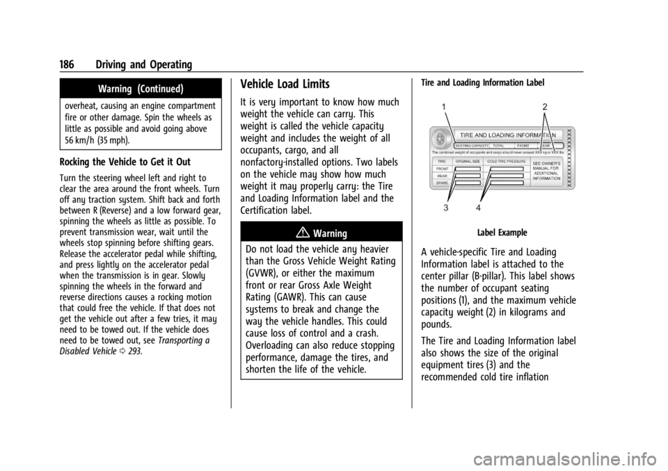
A vehicle-specific Tire and Loading
Information label is attached to the
center pillar (B-pillar). This label shows
the number of occupant seating
positions (1), and the maximum vehicle
capacity weight (2) in kilograms and
pounds.
The Tire and Loading Information label
also shows the size of the original
equipment tires (3) and the
recommended cold tire inflation
Page 188 of 351
Chevrolet Corvette Owner Manual (GMNA-Localizing-U.S./Canada/Mexico-
16287457) - 2023 - CRC - 3/10/22
Driving and Operating 187
pressures (4). For more information on
tires and inflation seeTires0271 and
Tire Pressure 0278.
There is also important loading
information on the vehicle Certification
label. It may show the Gross Vehicle
Weight Rating (GVWR) and the Gross
Axle Weight Rating (GAWR) for the
front and rear axle. See “Certification
Label” later in this section.
Steps for Determining Correct Load Limit–
1.
Locate the statement "The combined
weight of occupants and cargo
should never exceed XXX kg or
XXX lbs." on your vehicle’s placard.
2.Determine the combined weight of
the driver and passengers that will
be riding in your vehicle.
3.Subtract the combined weight of the
driver and passengers from XXX kg
or XXX lbs.
4.The resulting figure equals the
available amount of cargo and
luggage load capacity. For example,
if the "XXX" amount equals 1400 lbs.
and there will be five 150 lb
passengers in your vehicle, the
amount of available cargo and
luggage load capacity is 650 lbs.
(1400-750 (5 x 150) = 650 lbs.)
5.Determine the combined weight of
luggage and cargo being loaded on
the vehicle. That weight may not
safely exceed the available cargo and
luggage load capacity calculated in
Step 4.
6.If your vehicle will be towing a
trailer, load from your trailer will be
transferred to your vehicle. Consult
this manual to determine how this
reduces the available cargo and
luggage load capacity of your
vehicle.”
This vehicle is neither designed nor
intended to tow a trailer.
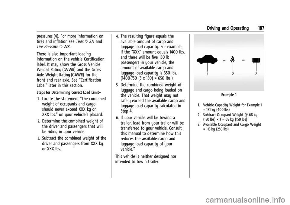
Example 1
1. Vehicle Capacity Weight for Example 1 = 181 kg (400 lbs)
2. Subtract Occupant Weight @ 68 kg (150 lbs) × 1 = 68 kg (150 lbs)
3. Available Occupant and Cargo Weight = 113 kg (250 lbs)
Page 189 of 351
Chevrolet Corvette Owner Manual (GMNA-Localizing-U.S./Canada/Mexico-
16287457) - 2023 - CRC - 3/10/22
188 Driving and Operating
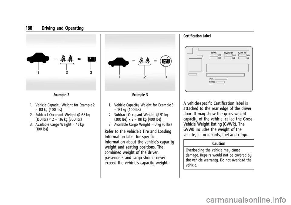
Example 2
1. Vehicle Capacity Weight for Example 2= 181 kg (400 lbs)
2. Subtract Occupant Weight @ 68 kg (150 lbs) × 2 = 136 kg (300 lbs)
3. Available Cargo Weight = 45 kg (100 lbs)
Example 3
1. Vehicle Capacity Weight for Example 3= 181 kg (400 lbs)
2. Subtract Occupant Weight @ 91 kg (200 lbs) × 2 = 181 kg (400 lbs)
3. Available Cargo Weight = 0 kg (0 lbs)
Refer to the vehicle's Tire and Loading
Information label for specific
information about the vehicle's capacity
weight and seating positions. The
combined weight of the driver,
passengers and cargo should never
exceed the vehicle's capacity weight.
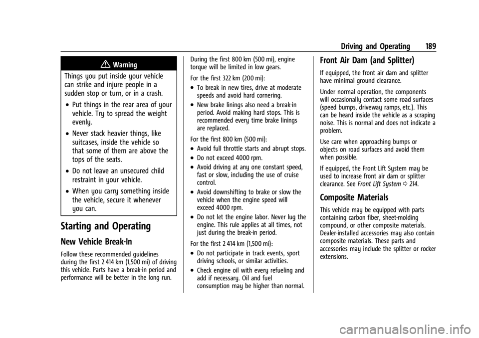
Certification Label
A vehicle-specific Certification label is
attached to the rear edge of the driver
door. It may show the gross weight
capacity of the vehicle, called the Gross
Vehicle Weight Rating (GVWR). The
GVWR includes the weight of the
vehicle, all occupants, fuel and cargo.
Caution
Overloading the vehicle may cause
damage. Repairs would not be covered by
the vehicle warranty. Do not overload the
vehicle.
Page 190 of 351
Chevrolet Corvette Owner Manual (GMNA-Localizing-U.S./Canada/Mexico-
16287457) - 2023 - CRC - 3/10/22
Driving and Operating 189
{Warning
Things you put inside your vehicle
can strike and injure people in a
sudden stop or turn, or in a crash.
.Put things in the rear area of your
vehicle. Try to spread the weight
evenly.
.Never stack heavier things, like
suitcases, inside the vehicle so
that some of them are above the
tops of the seats.
.Do not leave an unsecured child
restraint in your vehicle.
.When you carry something inside
the vehicle, secure it whenever
you can.
Starting and Operating
New Vehicle Break-In
Follow these recommended guidelines
during the first 2 414 km (1,500 mi) of driving
this vehicle. Parts have a break-in period and
performance will be better in the long run. During the first 800 km (500 mi), engine
torque will be limited in low gears.
For the first 322 km (200 mi):
.To break in new tires, drive at moderate
speeds and avoid hard cornering.
.New brake linings also need a break-in
period. Avoid making hard stops. This is
recommended every time brake linings
are replaced.
For the first 800 km (500 mi):
.Avoid full throttle starts and abrupt stops.
.Do not exceed 4000 rpm.
.Avoid driving at any one constant speed,
fast or slow, including the use of cruise
control.
.Avoid downshifting to brake or slow the
vehicle when the engine speed will
exceed 4000 rpm.
.Do not let the engine labor. Never lug the
engine. This rule applies at all times, not
just during the break-in period.
For the first 2 414 km (1,500 mi):
.Do not participate in track events, sport
driving schools, or similar activities.
.Check engine oil with every refueling and
add if necessary. Oil and fuel
consumption may be higher than normal.
Front Air Dam (and Splitter)
If equipped, the front air dam and splitter
have minimal ground clearance.
Under normal operation, the components
will occasionally contact some road surfaces
(speed bumps, driveway ramps, etc.). This
can be heard inside the vehicle as a scraping
noise. This is normal and does not indicate a
problem.
Use care when approaching bumps or
objects on road surfaces and avoid them
when possible.
If equipped, the Front Lift System may be
used to increase front air dam or splitter
clearance. See Front Lift System 0214.
Composite Materials
This vehicle may be equipped with parts
containing carbon fiber, sheet-molding
compound, or other composite materials.
Dealer-installed accessories may also contain
composite materials. These parts and
accessories may include the splitter or rocker
extensions.