fuse chart CHEVROLET DYNASTY 1993 Service Manual
[x] Cancel search | Manufacturer: CHEVROLET, Model Year: 1993, Model line: DYNASTY, Model: CHEVROLET DYNASTY 1993Pages: 2438, PDF Size: 74.98 MB
Page 30 of 2438
GROUP TAB LOCATOR
GENERAL INFORMATION
FUSE CHARTS AND RELAY BANKS
WIRING AND COMPONENT
IDENTIFICATION
SPLICE LOCATIONS
AA-C, D, P WIRING DIAGRAMS
AC-C, D/AY-C WIRING DIAGRAMS
AG-D, AJ-C WIRING DIAGRAMS
AP-P, D WIRING DIAGRAMS
Service Manual Comment Forms (Rear of Manual)
Page 123 of 2438
REAR LEVELING DIAGNOSTIC PROCEDURES
SELF-DIAGNOSTICS
A self-diagnostic procedure is available for the ser-
vice technician to use to detect system malfunctions.
BEFORE DIAGNOSTICS TEST
Check the 20 amp fuse (position W40) and the 30
amp circuit breaker (position W5) to be assured they
are functional components. Check all connectors that link the system into the
main body wiring harness. These include compressor,
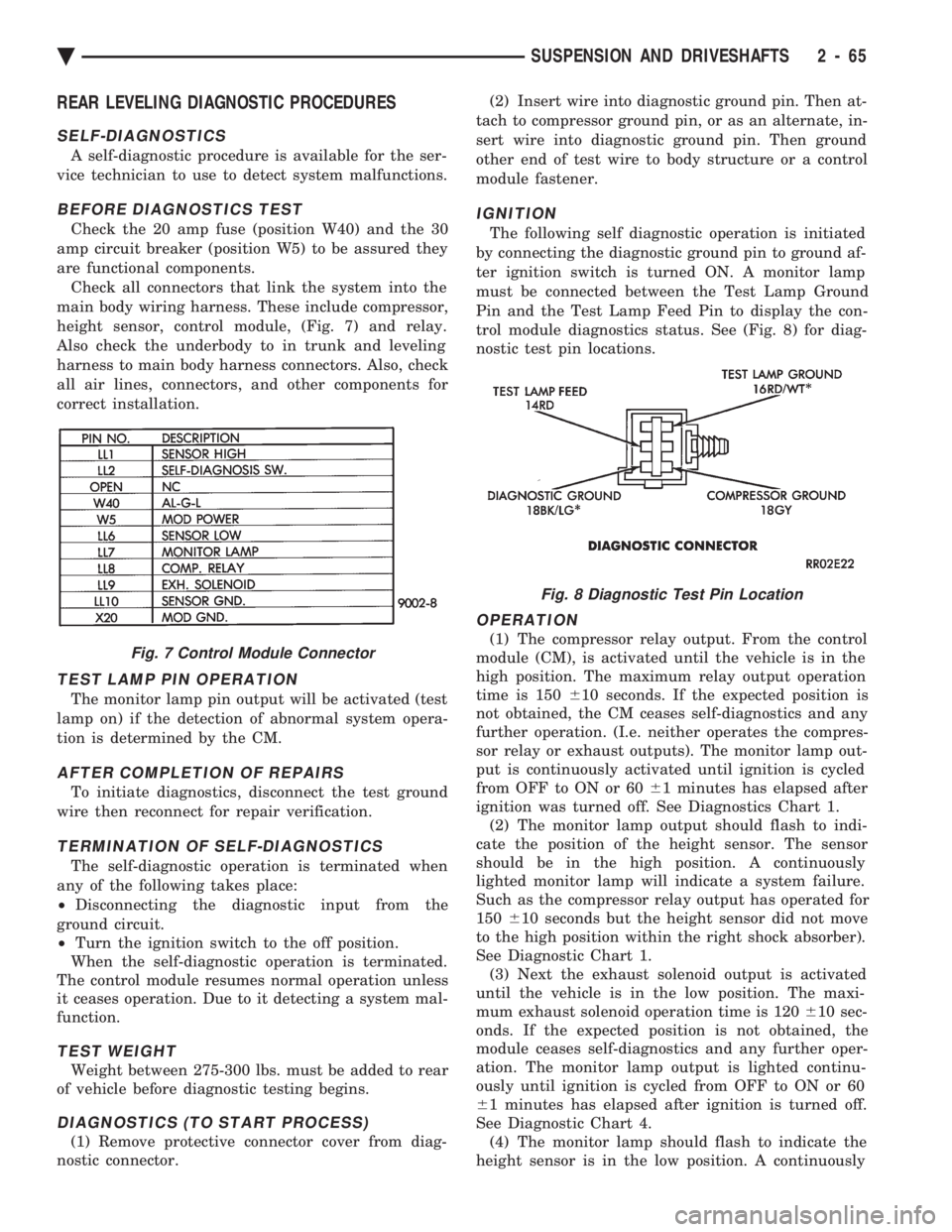
height sensor, control module, (Fig. 7) and relay.
Also check the underbody to in trunk and leveling
harness to main body harness connectors. Also, check
all air lines, connectors, and other components for
correct installation.
TEST LAMP PIN OPERATION
The monitor lamp pin output will be activated (test
lamp on) if the detection of abnormal system opera-
tion is determined by the CM.
AFTER COMPLETION OF REPAIRS
To initiate diagnostics, disconnect the test ground
wire then reconnect for repair verification.
TERMINATION OF SELF-DIAGNOSTICS
The self-diagnostic operation is terminated when
any of the following takes place:
² Disconnecting the diagnostic input from the
ground circuit.
² Turn the ignition switch to the off position.
When the self-diagnostic operation is terminated.
The control module resumes normal operation unless
it ceases operation. Due to it detecting a system mal-
function.
TEST WEIGHT
Weight between 275-300 lbs. must be added to rear
of vehicle before diagnostic testing begins.
DIAGNOSTICS (TO START PROCESS)
(1) Remove protective connector cover from diag-
nostic connector. (2) Insert wire into diagnostic ground pin. Then at-
tach to compressor ground pin, or as an alternate, in-
sert wire into diagnostic ground pin. Then ground
other end of test wire to body structure or a control
module fastener.
IGNITION
The following self diagnostic operation is initiated
by connecting the diagnostic ground pin to ground af-
ter ignition switch is turned ON. A monitor lamp
must be connected between the Test Lamp Ground
Pin and the Test Lamp Feed Pin to display the con-
trol module diagnostics status. See (Fig. 8) for diag-
nostic test pin locations.
OPERATION
(1) The compressor relay output. From the control
module (CM), is activated until the vehicle is in the
high position. The maximum relay output operation
time is 150 610 seconds. If the expected position is
not obtained, the CM ceases self-diagnostics and any
further operation. (I.e. neither operates the compres-
sor relay or exhaust outputs). The monitor lamp out-
put is continuously activated until ignition is cycled
from OFF to ON or 60 61 minutes has elapsed after
ignition was turned off. See Diagnostics Chart 1. (2) The monitor lamp output should flash to indi-
cate the position of the height sensor. The sensor
should be in the high position. A continuously
lighted monitor lamp will indicate a system failure.
Such as the compressor relay output has operated for
150 610 seconds but the height sensor did not move
to the high position within the right shock absorber).
See Diagnostic Chart 1. (3) Next the exhaust solenoid output is activated
until the vehicle is in the low position. The maxi-
mum exhaust solenoid operation time is 120 610 sec-
onds. If the expected position is not obtained, the
module ceases self-diagnostics and any further oper-
ation. The monitor lamp output is lighted continu-
ously until ignition is cycled from OFF to ON or 60
6 1 minutes has elapsed after ignition is turned off.
See Diagnostic Chart 4. (4) The monitor lamp should flash to indicate the
height sensor is in the low position. A continuouslyFig. 7 Control Module Connector
Fig. 8 Diagnostic Test Pin Location
Ä SUSPENSION AND DRIVESHAFTS 2 - 65
Page 559 of 2438
VEHICLE SPEED SENSOR TEST
For testing of the vehicle speed sensor and related
components using DRB II, refer to the appropriate
Powertrain Diagnostics Test Procedure Manual.
PRINTED CIRCUIT BOARD REPLACEMENT
(1) Remove cluster bezel.
(2) Remove instrument cluster.
(3) Remove tachometer drive module, if equipped.
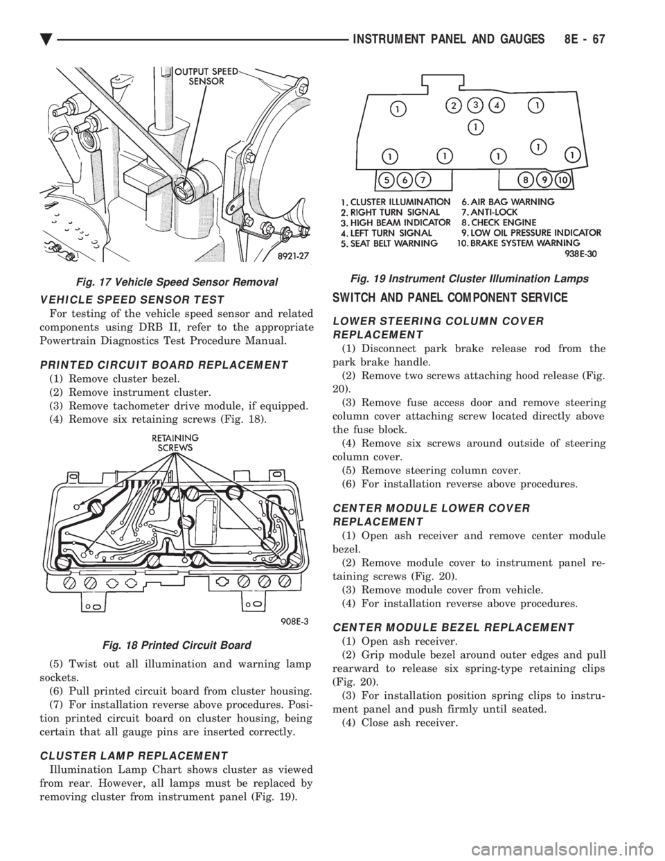
(4) Remove six retaining screws (Fig. 18).
(5) Twist out all illumination and warning lamp
sockets. (6) Pull printed circuit board from cluster housing.
(7) For installation reverse above procedures. Posi-
tion printed circuit board on cluster housing, being
certain that all gauge pins are inserted correctly.
CLUSTER LAMP REPLACEMENT
Illumination Lamp Chart shows cluster as viewed
from rear. However, all lamps must be replaced by
removing cluster from instrument panel (Fig. 19).
SWITCH AND PANEL COMPONENT SERVICE
LOWER STEERING COLUMN COVER REPLACEMENT
(1) Disconnect park brake release rod from the
park brake handle. (2) Remove two screws attaching hood release (Fig.
20). (3) Remove fuse access door and remove steering
column cover attaching screw located directly above
the fuse block. (4) Remove six screws around outside of steering
column cover. (5) Remove steering column cover.
(6) For installation reverse above procedures.
CENTER MODULE LOWER COVER REPLACEMENT
(1) Open ash receiver and remove center module
bezel. (2) Remove module cover to instrument panel re-
taining screws (Fig. 20). (3) Remove module cover from vehicle.
(4) For installation reverse above procedures.
CENTER MODULE BEZEL REPLACEMENT
(1) Open ash receiver.
(2) Grip module bezel around outer edges and pull
rearward to release six spring-type retaining clips
(Fig. 20). (3) For installation position spring clips to instru-
ment panel and push firmly until seated. (4) Close ash receiver.
Fig. 17 Vehicle Speed Sensor Removal
Fig. 18 Printed Circuit Board
Fig. 19 Instrument Cluster Illumination Lamps
Ä INSTRUMENT PANEL AND GAUGES 8E - 67
Page 623 of 2438
(3) Secure arm to pivot with attaching nut and
tighten 17 to 22 N Im (155 to 195 in. lbs.) torque.
(4) Close head cover and remove pin from arm pin
hole.
WIPER ARM ADJUSTMENT
FRONT ARM ADJUSTMENT
(1) Cycle the wiper motor into the PARK position.
(2) Check the tips of the blades in blackout area.
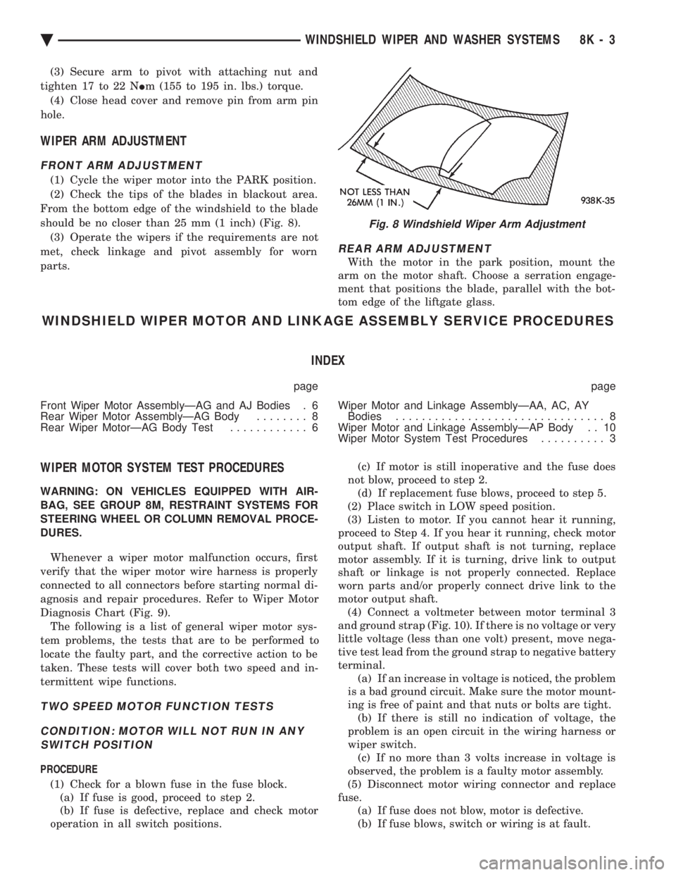
From the bottom edge of the windshield to the blade
should be no closer than 25 mm (1 inch) (Fig. 8). (3) Operate the wipers if the requirements are not
met, check linkage and pivot assembly for worn
parts.
REAR ARM ADJUSTMENT
With the motor in the park position, mount the
arm on the motor shaft. Choose a serration engage-
ment that positions the blade, parallel with the bot-
tom edge of the liftgate glass.
WINDSHIELD WIPER MOTOR AND LINKAGE ASSEMBLY SERVICE PROCEDURES
INDEX
page page
Front Wiper Motor AssemblyÐAG and AJ Bodies . 6
Rear Wiper Motor AssemblyÐAG Body ........ 8
Rear Wiper MotorÐAG Body Test ............ 6 Wiper Motor and Linkage AssemblyÐAA, AC, AY
Bodies ................................ 8
Wiper Motor and Linkage AssemblyÐAP Body . . 10
Wiper Motor System Test Procedures .......... 3
WIPER MOTOR SYSTEM TEST PROCEDURES
WARNING: ON VEHICLES EQUIPPED WITH AIR-
BAG, SEE GROUP 8M, RESTRAINT SYSTEMS FOR
STEERING WHEEL OR COLUMN REMOVAL PROCE-
DURES.
Whenever a wiper motor malfunction occurs, first
verify that the wiper motor wire harness is properly
connected to all connectors before starting normal di-
agnosis and repair procedures. Refer to Wiper Motor
Diagnosis Chart (Fig. 9). The following is a list of general wiper motor sys-
tem problems, the tests that are to be performed to
locate the faulty part, and the corrective action to be
taken. These tests will cover both two speed and in-
termittent wipe functions.
TWO SPEED MOTOR FUNCTION TESTS
CONDITION: MOTOR WILL NOT RUN IN ANY SWITCH POSITION
PROCEDURE
(1) Check for a blown fuse in the fuse block. (a) If fuse is good, proceed to step 2.
(b) If fuse is defective, replace and check motor
operation in all switch positions. (c) If motor is still inoperative and the fuse does
not blow, proceed to step 2. (d) If replacement fuse blows, proceed to step 5.
(2) Place switch in LOW speed position.
(3) Listen to motor. If you cannot hear it running,
proceed to Step 4. If you hear it running, check motor
output shaft. If output shaft is not turning, replace
motor assembly. If it is turning, drive link to output
shaft or linkage is not properly connected. Replace
worn parts and/or properly connect drive link to the
motor output shaft. (4) Connect a voltmeter between motor terminal 3
and ground strap (Fig. 10). If there is no voltage or very
little voltage (less than one volt) present, move nega-
tive test lead from the ground strap to negative battery
terminal. (a) If an increase in voltage is noticed, the problem
is a bad ground circuit. Make sure the motor mount-
ing is free of paint and that nuts or bolts are tight. (b) If there is still no indication of voltage, the
problem is an open circuit in the wiring harness or
wiper switch. (c) If no more than 3 volts increase in voltage is
observed, the problem is a faulty motor assembly.
(5) Disconnect motor wiring connector and replace
fuse. (a) If fuse does not blow, motor is defective.
(b) If fuse blows, switch or wiring is at fault.
Fig. 8 Windshield Wiper Arm Adjustment
Ä WINDSHIELD WIPER AND WASHER SYSTEMS 8K - 3
Page 727 of 2438
POWER WINDOWS
CONTENTS
page page
BENCH REPAIR OF REGULATOR AND MOTOR CONVENTIONAL REGULATORS .......... 5
GEAR AND PINION REPLACEMENT AND LUBRICATION ....................... 3
GENERAL INFORMATION .................. 1
MOTOR REPLACEMENT ................... 7
MOTOR REPLACEMENT CONVENTIONAL REGULATORS ....................... 3
MOTOR REPLACEMENTÐFLEX DRIVE REGULATORS ......................... 5 POWER WINDOW CABLE HOUSING/MOTOR RE-
PLACEMENTÐAC and AY BODIES ........ 7
QUARTER WINDOW MOTOR REPLACEMENTÐ AJ BODY ............................. 9
QUARTER WINDOW REPLACEMENTÐ AJ BODY ............................. 8
WINDOW LIFT MOTOR TEST .............. 1
WINDOW LIFT SWITCH TEST .............. 1
WIRING VOLTAGE TEST .................. 1
GENERAL INFORMATION
Front and rear door window lift motors are of the
permanent magnet type. A positive and negative bat-
tery connection to either of the two motor terminals
will cause the motor to rotate in one direction. Re-
versing current through these same two connections
will cause the motor to rotate in the opposite direc-
tion. Each individual motor is grounded through the
master switch by a black wire attached to the left
cowl panel. It is necessary that the window be free to slide up
and down in the glass channels or tubes and tracks.
If the window is not free to move up and down, the
window lift motor will not be able to move the glass. To determine if the glass is free is to disconnect the
regulator from the glass lift plate, and slide the win-
dow up and down by hand. For conventional arm-sec-
tor regulators, after the lift plate is detached from
the glass, it will slide off the regulator drive arm.
Flex-drive regulators may be detached the same way
or by removing one screw holding the flex rack to the
lift plate drive arm.
WIRING VOLTAGE TEST
The following wiring test determines whether or
not voltage is continuous through the body harness
to switch. After removing switch for testing purposes, care-
fully separate multiple terminal block on wiring har-
ness from switch body. With ignition switch ON
connect one lead of test light to black (or gray) wire
terminal and touch other test light lead to tan wire
terminal. If the test light comes on, the wiring cir-
cuit between the battery and switch is functional. If
light does not come on, check 30 amp main fuse (cir- cuit breaker) or for a broken wire. For wiring, spe-
cific connector type and location, refer to Group 8W,
Wiring Diagrams.
WINDOW LIFT SWITCH TEST
For switch testing, remove the switch from its
mounting. Using an ohmmeter, refer to Window
Switch Continuity Charts to determine if continuity
is correct. If the results are not obtained, replace the
switch. AC and AY Bodies are equipped with an Auto-
Down feature. This feature allows the operator to
lower the driver's window without having to hold the
switch in the down position. The Auto-Down feature
can be activated by pressing the down switch past
the first detent (Stop). To test the auto-down feature, operate the window
in the normal up and down mode. If the window
works correctly in the normal mode, but not in the
auto-down mode, replace the switch. To test the window switch (other than Auto-Down
mode), install a known good switch.
WINDOW LIFT MOTOR TEST
(1) Connect positive (+) lead from a test battery to
either of the two motor terminals. (2) Connect negative (-) lead from test battery to
remaining motor terminal. (3) The motor should now rotate in one direction to
either move window up or down. (a) If window happens to already be in full UP
position and motor is connected so as to rotate in
UP direction no movement will be observed. (b) Likewise, motor connected to DOWN direc-
tion rotation, no movement will be observed if win-
dow is already in full DOWN position.
Ä POWER WINDOWS 8S - 1
Page 751 of 2438
GENERAL INFORMATION
CONTENTS
page page
CIRCUIT IDENTIFICATION ................. 3
COMPONENT IDENTIFICATION ............. 3
CONNECTORS ........................... 4
FUSIBLE LINKS ......................... 4
HARNESS REPAIR ....................... 4
LOCATING A SYSTEM .................... 3 SECONDARY IGNITION WIRING
............ 1
SPLICE LOCATIONS ...................... 3
SYMBOLS, FUSES AND RELAYS ........... 7
TROUBLESHOOTING WIRING PROBLEMS .... 4
WIRE CODE IDENTIFICATION .............. 2
WIRING DIAGRAM SHEETS AND INDEXES . . . 1
The wiring diagrams contain the latest information
at the time of publication. Throughout this group ref-
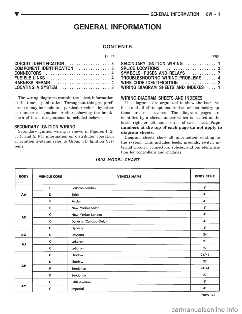
erences may be made to a particular vehicle by letter
or number designation. A chart showing the break-
down of these designations is included below.
SECONDARY IGNITION WIRING
Secondary ignition wiring is shown in Figures 1, 2,
3, 4, and 5. For information on distributor operation
or ignition systems refer to Group 8D Ignition Sys-
tems.
WIRING DIAGRAM SHEETS AND INDEXES
The diagrams are organized to show the basic ve-
hicle and all of its options. Add-on or non-factory op-
tions are not covered. The diagram pages are
identified by a sheet number which is located at the
lower right or left hand corner of each sheet. Page
numbers at the top of each page do not apply to
diagram sheets. Diagram sheets show all information relating to
the system. This includes feeds, grounds, switch in-
ternal circuity, connectors, splices, and pin identifica-
tion for controllers and modules.
1993 MODEL CHART
Ä GENERAL INFORMATION 8W - 1
Page 753 of 2438
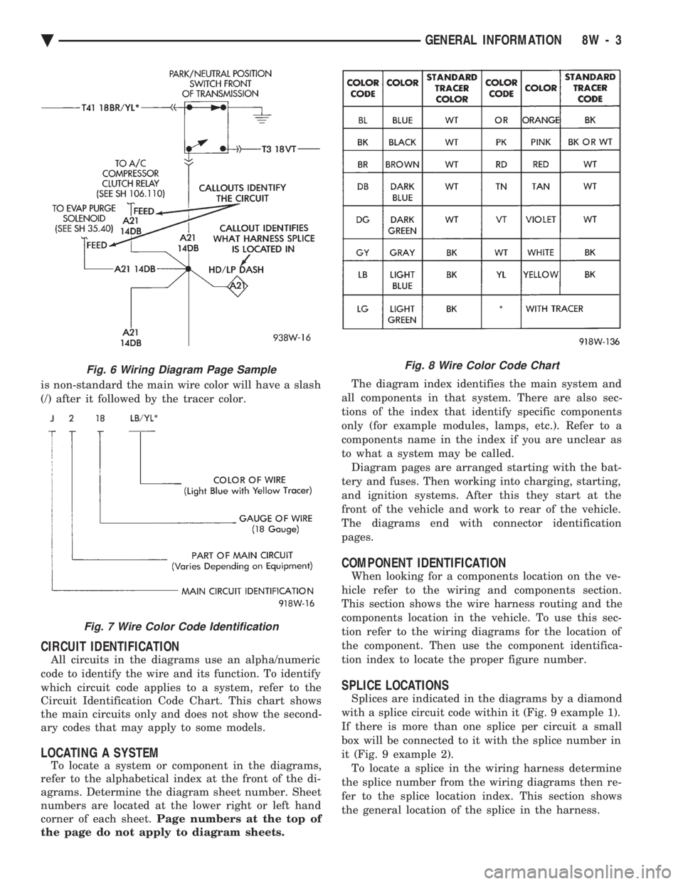
is non-standard the main wire color will have a slash
(/) after it followed by the tracer color.
CIRCUIT IDENTIFICATION
All circuits in the diagrams use an alpha/numeric
code to identify the wire and its function. To identify
which circuit code applies to a system, refer to the
Circuit Identification Code Chart. This chart shows
the main circuits only and does not show the second-
ary codes that may apply to some models.
LOCATING A SYSTEM
To locate a system or component in the diagrams,
refer to the alphabetical index at the front of the di-
agrams. Determine the diagram sheet number. Sheet
numbers are located at the lower right or left hand
corner of each sheet. Page numbers at the top of
the page do not apply to diagram sheets. The diagram index identifies the main system and
all components in that system. There are also sec-
tions of the index that identify specific components
only (for example modules, lamps, etc.). Refer to a
components name in the index if you are unclear as
to what a system may be called. Diagram pages are arranged starting with the bat-
tery and fuses. Then working into charging, starting,
and ignition systems. After this they start at the
front of the vehicle and work to rear of the vehicle.
The diagrams end with connector identification
pages.
COMPONENT IDENTIFICATION
When looking for a components location on the ve-
hicle refer to the wiring and components section.
This section shows the wire harness routing and the
components location in the vehicle. To use this sec-
tion refer to the wiring diagrams for the location of
the component. Then use the component identifica-
tion index to locate the proper figure number.
SPLICE LOCATIONS
Splices are indicated in the diagrams by a diamond
with a splice circuit code within it (Fig. 9 example 1).
If there is more than one splice per circuit a small
box will be connected to it with the splice number in
it (Fig. 9 example 2). To locate a splice in the wiring harness determine
the splice number from the wiring diagrams then re-
fer to the splice location index. This section shows
the general location of the splice in the harness.
Fig. 6 Wiring Diagram Page Sample
Fig. 7 Wire Color Code Identification
Fig. 8 Wire Color Code Chart
Ä GENERAL INFORMATION 8W - 3
Page 754 of 2438
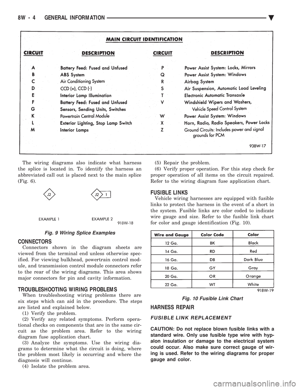
The wiring diagrams also indicate what harness
the splice is located in. To identify the harness an
abbreviated call out is placed next to the main splice
(Fig. 6).
CONNECTORS
Connectors shown in the diagram sheets are
viewed from the terminal end unless otherwise spec-
ified. For viewing bulkhead, powertrain control mod-
ule, and transmission control module connectors refer
to the rear of the wiring diagrams. This area shows
major connectors for pin and cavity information.
TROUBLESHOOTING WIRING PROBLEMS
When troubleshooting wiring problems there are
six steps which can aid in the procedure. The steps
are listed and explained below. (1) Verify the problem.
(2) Verify any related symptoms. Perform opera-
tional checks on components that are in the same cir-
cuit as the problem area. Refer to the wiring
diagram fuse application chart. (3) Analyze the symptoms. Use the wiring dia-
grams to determine what the circuit is doing, where
the problem most likely is occurring and where the
diagnosis will continue. (4) Isolate the problem area. (5) Repair the problem.
(6) Verify proper operation. For this step check for
proper operation of all items on the circuit repaired.
Refer to the wiring diagram fuse application chart.
FUSIBLE LINKS
Vehicle wiring harnesses are equipped with fusible
links to protect the harness in the event of a short in
the system. Fusible links are color coded to indicate
wire gauge and size. Refer to the fusible link chart
for color and gauge identification (Fig. 10).
HARNESS REPAIR
FUSIBLE LINK REPLACEMENT
CAUTION: Do not replace blown fusible links with a
standard wire. Only use fusible type wire with hyp-
alon insulation or damage to the electrical system
could occur. Also make sure correct gauge of wir-
ing is used. Refer to the wiring diagrams for proper
gauge and color.
Fig. 9 Wiring Splice Examples
Fig. 10 Fusible Link Chart
8W - 4 GENERAL INFORMATION Ä
Page 757 of 2438
(14) Center the heat shrink tubing over the joint
and heat using a heat gun. Heat the joint until the
tubing is tightly sealed and sealant comes out of both
ends of the tubing. (15) Insert the repaired wire into the connector.
(16) Install the connector locking wedge and recon-
nect the connector to its mating half. (17) Re-tape the wire harness starting 1-1/2 inches
behind the connector and 2 inches past the repair. (18) Connect battery and test all affected systems.
SYMBOLS, FUSES AND RELAYS
Various symbols are used throughout the wiring
diagrams. These symbols can be identified by refer-
ring to the symbol identification chart (Fig. 15). For fuse block, relay bank, or power distribution
center information refer to the fuse charts and relay
bank section.
CAUTION: When replacing a blown fuse it is impor-
tant to replace it with a fuse having the correct am-
perage rating. The use of a fuse with a rating other
than indicated may result in an electrical overload.
If a proper rated fuse continues to blow, it indicates
a problem that should be corrected.
Ä GENERAL INFORMATION 8W - 7
Page 759 of 2438

FUSE CHARTS AND RELAY BANKS
INDEX
Caption Fig.
Fuse Block and Relay Bank AA Body .................1
Fuse Block AC, AY Body .........................2
Fuse Block AG, AJ Body .........................3
Fuse Block and Relay Bank AP Body .................4Caption Fig.
Power Distribution Center AC, AY Body ................7
Power Distribution Center AG, AJ Body ................8
Relay Bank AC, AY Body .........................5
Relay Bank AG, AJ Body .........................6
Ä FUSE CHARTS AND RELAY BANKS 8W - 9