fuses CHEVROLET DYNASTY 1993 Service Manual
[x] Cancel search | Manufacturer: CHEVROLET, Model Year: 1993, Model line: DYNASTY, Model: CHEVROLET DYNASTY 1993Pages: 2438, PDF Size: 74.98 MB
Page 136 of 2438
(3) Check solenoid to volume canister joint.
² Front strut to solenoid valve connection.
² Rear spring to solenoid valve connection.
(4) Check air line for ruptures, cuts, splits or heat
damage. Use a soap and water solution or a liquid de-
veloped for leak detection.
SYSTEM OPERATION
ENGINE RUN OPERATION
The system will compensate for load
addition/removal when.
² The trunk and all doors are closed.
² The engine speed exceeds 600 R.P.M.
² Throttle angle is less than 65 degrees.
² The brake is not applied.
² You are not cornering above 10 mph.
² There is not a charging system problem with the
vehicle.
ENGINE OFF OPERATION
After passengers/load is removed from the vehicle
the system will correct the vehicle attitude after:
² The trunk and all doors are closed.
² The ignition switch is in the OFF position.
Opening the a door or trunk wakes up the body
computer and the air suspension module. The air
suspension system is now capable of leveling, if
required.
LONG TERM IGNITION OFF OPERATION
The system is capable of one an additional leveling
cycle. After 2 continuous hours of ignition key off and
no door open or trunk open activities. This feature is
implemented to eliminate possible ice freeze-up be-
tween the tire and the inner fender shield.
SYSTEM OPERATION INHIBITORS
The air suspension system is inhibited when:
² The trunk is open.
² A door(s) is/are open.
² The brake pedal is engaged.
² The throttle is at the wide open position.
² The charging system fails.
The maximum compressor pump or exhaust
time is 3 minutes.
SYSTEM FAILURES
Vehicles equipped with air suspension and overhead
console. Will alert the driver of an air suspension
system malfunction. A warning Check Air Suspension
will appear on the overhead console screen.
SAFETY CONCERNS
WARNING: REAR AIR SPRINGS MUST BE DEFLATED
BEFORE BEING REMOVED FROM THE VEHICLE.
WARNING: OPEN TRUNK, OR DOOR(S) OR REMOVE
GROUND STRAP FROM BATTERY BEFORE HOIST-
ING OR JACKING A VEHICLE DURING MECHANICAL
REPAIRS.
WARNING: IF THE VEHICLE NEEDS SERVICE OR
REPAIR OF THE REAR SHOCK ABSORBERS OR
REAR AXLE PIVOT BUSHINGS. THE REAR AIR
SPRINGS MUST HAVE THE AIR PRESSURE RE-
MOVED BEFORE THE VEHICLE CAN BE SERVICED
SAFELY.
SHIPPING MODE
(1) Removing shipping height signal for customer
use.
² Use DRB II tester and 1991 Chassis (Air Suspen-
sion) service cartridge.
² Follow DRB II requirements to cancel shipping
height message in the body computer.
² Connect the Ignition Off Draw (I.O.D.) circuit.
The connection of the IOD circuit will cancel
the Shipping height signal. (2) Return to shipping height.
² Set shipping command in the body computer using
the DRB II and the 1991 Chassis (Air suspension)
service cartridge.
² Disconnect the I.O.D. connector.
DIAGNOSIS
INITIAL DIAGNOSTIC CHECK
(1) Check for blown or missing fuses.
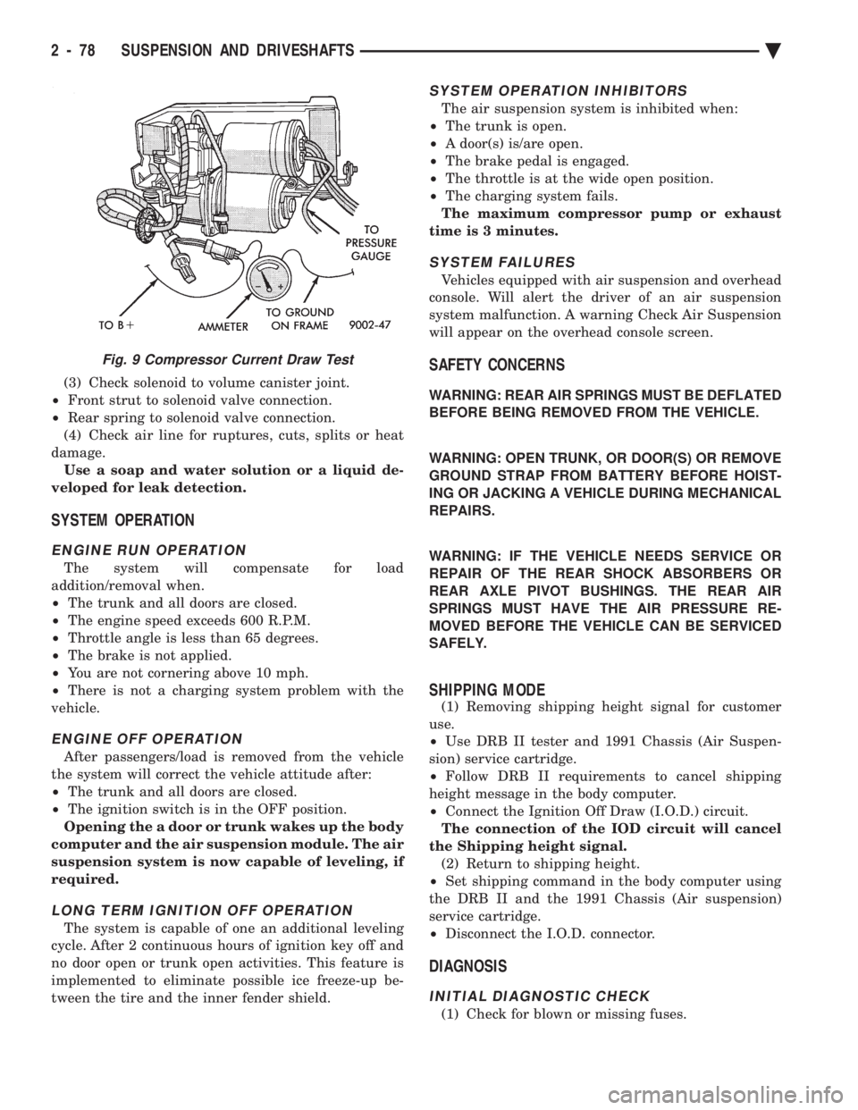
Fig. 9 Compressor Current Draw Test
2 - 78 SUSPENSION AND DRIVESHAFTS Ä
Page 238 of 2438
In order to effectively diagnose an Anti-Lock Brake
System (ABS) condition. It is important to read Sec-
tion 1 of this manual, Anti-Lock Brake System De-
scription. This section will give you information on
the function of the ABS components. Then follow the
diagnostic procedures outlined in this section. Many conditions that generate customer com-
plaints of the ABS system may be normal operating
conditions. These conditions though are judged to be
a problem due to unfamiliarity with the ABS system.
These conditions can be recognized without perform-
ing extensive diagnostic work, given adequate under-
standing of operating principles and performance
characteristics of the ABS system. See Section 1 of
this manual to familiarize yourself with the operat-
ing principles of the ABS system.
DEFINITIONS
Several abbreviations are used in this manual.
They are presented here for reference.
² CABÐController Anti-Lock Brake
² ABSÐAnti-Lock Brake System
² PSIÐPounds per Square Inch (pressure)
² WSSÐWheel Speed Sensor
ABS CONTROLLER ANTI-LOCK BRAKE (CAB) SER-
VICE PRECAUTIONS
The ABS system uses an electronic control module,
the (CAB). This module is designed to withstand nor-
mal current draws associated with vehicle operation.
However care must be taken to avoid overloading the
(CAB) circuits. In testing for open or short circuits, do
not ground or apply voltage to any of the circuits unless
instructed to do so by the appropriate diagnostic pro-
cedure. These circuits should only be tested using a
high impedance multi-meter, special tools or the DRB
II tester as described in this section. Power should
never be removed or applied to any control module with
the ignition in the ON position. Before removing or
connecting battery cables, fuses, or connectors, always
turn the ignition to the OFF position.
ABS SYSTEM GENERAL SERVICE PRECAUTIONS
TEST DRIVING ABS COMPLAINT VEHICLES
Most ABS complaints will require a test drive as a
part of the diagnostic procedure. The purpose of the
test drive is to duplicate the condition. Before test driving a brake complaint vehicle,
especially if the Red Brake Warning Lamp is on.
Test the brake function at low speed to be sure
that the car will stop normally. Remember that
conditions that result in illumination of the Red
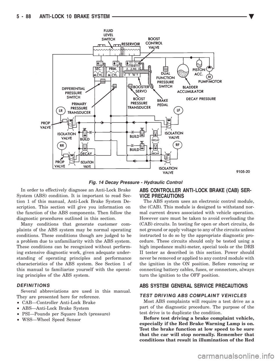
Fig. 14 Decay Pressure - Hydraulic Control
5 - 88 ANTI-LOCK 10 BRAKE SYSTEM Ä
Page 274 of 2438
In order to effectively diagnose an Anti-Lock Brake
System (ABS) condition. It is important to read Anti-
Lock Brake System Description. And to follow the
diagnostic procedures outlined in this section. Many conditions that generate customer complaints
may be normal operating conditions, but are judged to
be a problem due to not being familiar with the ABS
system. These conditions can be recognized without
performing extensive diagnostic work. Given adequate
understanding of the operating principles and perfor-
mance characteristics of the ABS system. See Section 1
of this manual to familiarize yourself with the operat-
ing principles of the ABS system.
DEFINITIONS
Several abbreviations are used in this manual. They
are presented here for reference.
² CABÐController Anti-Lock Brake
² ABSÐAnti-Lock Brake System
² PSIÐPounds per Square Inch (pressure)
² WSSÐWheel Speed Sensor
ABS COMPUTER SYSTEM SERVICE PRECAUTIONS
The ABS system uses an electronic control module,
the (CAB). This module is designed to withstand nor-
mal current draws associated with vehicle operation.
However care must be taken to avoid overloading the
(CAB) circuits. In testing for open or short circuits,
do not ground or apply voltage to any of the
circuits unless instructed to do so by the appro-
priate diagnostic procedure. These circuits should
only be tested using a high impedance multi-meter,
special tools or the DRB II tester as described in this
section. Power should never be removed or applied to
any control module with the ignition in the ON posi-
tion. Before removing or connecting battery cables,
fuses, or connectors, always turn the ignition to the
OFF position.
ABS GENERAL SERVICE PRECAUTIONS
TEST DRIVING ABS COMPLAINT VEHICLES
Most ABS complaints will require a test drive as a
part of the diagnostic procedure. The purpose of the
test drive is to duplicate the condition. Remember conditions that result in the turn-
ing on of the Red Brake Warning Lamp may
indicate reduced braking ability. The following
procedure should be used to test drive an ABS
complaint vehicle. Before test driving a brake complaint vehicle, note
whether the Red or Amber Brake Warning Lamp is
turned on. If it is the Red Brake Warning Lamp, refer
to the standard brake, Control Valves Section in the
brake group of this manual. If the Amber Anti-Lock
Warning light was/is on, read record and erase the
fault. While the Amber ABS Warning Lamp is on the
ABS system is not functional. When the Am- ber Anti-Lock Warning Lamp is on only the Anti-Lock
function of the brake system if affected. The standard
brake system and the ability to stop the car is not be
affected if only the Amber Anti-Lock Warning Lamp is
on. (1) Turn the key to the off position and then back to
the on position. Note whether the Amber ABS Warning
Lamp continues to stay on. If it does refer to the 1993
M.Y. Bendix Anti-Lock 6 Diagnostic Manual for the
required test procedures. (2) If the Amber ABS Warning Lamp goes out, shift
into gear and drive the car to a speed of 5 mph to
complete the ABS start up cycle. If at this time the
Amber ABS Warning Lamp goes on refer to the Bendix
Anti-Lock 6 Diagnostic Manual. (3) If the Amber ABS Warning Lamp remains OUT,
drive the vehicle a short distance. During this test
drive be sure that the vehicle achieves at least 25 mph.
Brake to at least one complete stop and again acceler-
ate to 25 mph. (4) If a functional problem with the A.B.S. system is
determined while test driving a vehicle. Refer to the
Bendix Anti-Lock 6 Diagnostics Manual for required
test procedures and proper use of the DRB II tester.
ABS BRAKE SYSTEM ON VEHICLE SERVICE
The following are general precautions which
should be observed when servicing and diagnos-
ing the ABS system and/or other vehicle systems.
Failure to observe these precautions may result
in ABS system damage. (1) If welding work is to be performed on a vehicle
using an arc welder, the (CAB) should be disconnected
before the welding operation begins. (2) The (CAB) and modulator assembly 10 way con-
nector should never be connected or disconnected with
the ignition in the on position. (3) Some components of the ABS system are not
serviced separately and must be serviced as complete
assemblies. Do not disassemble any component which
is designated as non-serviceable.
CAUTION: Brake fluid will damage painted surfaces.
If brake fluid is spilled on any painted surfaces, wash
off with water immediately.
WHEEL SPEED SENSOR CABLES
Proper installation of the Wheel Speed Sensor Cables
is critical to continued system operation. Be sure that
cables are installed, routed and clipped properly. Fail-
ure to install speed sensor cables as shown in the on
car service section of this manual. May result in
contact with moving parts or over extension of cables,
resulting in component failure and an open circuit.
5 - 124 ANTI-LOCK 6 BRAKE SYSTEM Ä
Page 309 of 2438
earlier in this service manual supplement. Then follow
the diagnostic procedures outlined in this section. Many conditions that generate customer complaints
may be normal operating conditions, but are judged to
be a problem due to not being familiar with the ABS
system. These conditions can be recognized without
performing extensive diagnostic work, given adequate
understanding of the operating principles and perfor-
mance characteristics of the ABS system.
DEFINITIONS
Several abbreviations are used in this manual. They
are presented here for reference.
² CABÐController Antilock Brake
² ABSÐAntilock Brake System
² PSIÐPounds per Square Inch (pressure)
² WSSÐWheel Speed Sensor
² ACÐAlternating Current
ABS COMPUTER SYSTEM SERVICE PRECAUTIONS
The ABS system uses an electronic control module,
the CAB. This module is designed to withstand normal
current draws associated with vehicle operation. How-
ever care must be taken to avoid overloading the CAB
circuits. In testing for open or short circuits, do
not ground or apply voltage to any of the circuits
unless instructed to do so by the appropriate
diagnostic procedure. These circuits should only be
tested using a high impedance multi-meter, special
tools or the DRB II tester as described in this section.
Power should never be removed or applied to any
control module with the ignition in the ON position.
Before removing or connecting battery cables, fuses, or
connectors, always turn the ignition to the OFF posi-
tion.
ABS GENERAL SERVICE PRECAUTIONS
TEST DRIVING ABS COMPLAINT VEHICLES
Most ABS complaints will require a test drive as a
part of the diagnostic procedure. The purpose of the
test drive is to duplicate the condition. Remember conditions that result in the turn-
ing on of the Red Brake Warning Lamp may
indicate reduced braking ability. The following
procedure should be used to test drive an ABS
complaint vehicle. Before test driving a brake complaint vehicle, note
whether the Red or Amber Brake Warning Lamp is
turned on. If the Red Brake Warning Lamp, is
turned on, refer to the base brake Control Valves
Section in the Front Wheel Drive, chassis service
manual. If the Amber Antilock Warning light was or
is on, read record and erase the faults. While the
Amber ABS Warning Lamp is on the ABS system is
not functional. The standard brake system and abil- ity to stop the car is not affected, if only the Amber
Antilock Warning Lamp is on.
(1) Turn ignition key to the off position and then
back to the on position. Note whether the Amber ABS
Warning Lamp continues to stay on. If it does refer to
the 1994 Bendix Antilock 4 Brake System Diagnostic
Manual for the required diagnostic test procedures. (2) If the Amber ABS Warning Lamp goes out, shift
vehicle into gear and drive car to a speed of 5 mph to
complete the ABS drive-off cycle. If at this time, the
Amber ABS Warning Lamp goes on refer to the 1994
Bendix Antilock 4 Brake System Diagnostic Manual. (3) If the Amber ABS Warning Lamp remains OUT,
continue to drive the vehicle a short distance. During
this test drive be sure that the vehicle achieves at least
25 mph. Brake to at least one complete stop and again
accelerate to 25 mph. (4) If a functional problem with the ABS system is
determined while test driving a vehicle. Refer to the
Bendix Antilock 4 Brake System Diagnostics Manual
for required diagnostic test procedures and proper use
of the DRB II tester.
ABS BRAKE SYSTEM ON VEHICLE SERVICE
The following are general precautions which
should be observed whenever servicing and or
diagnosing the ABS system and other vehicle
electronic systems. Failure to observe these pre-
cautions may result in ABS system damage. (1) If welding work is to be performed on a vehicle
using an arc welder. The wiring harness connector
should be disconnected from the CAB before beginning
any welding operation. (2) The CAB 60 way connector and modulator as-
sembly 10 way connector, should never be connected or
disconnected with the ignition in the on position. (3) Some components of Bendix Antilock 4 Brake
System assemblies can not be serviced separately from
the assembly and will require replacement of the
complete assembly for servicing. Do not disassemble
any component which is designated as non-serviceable.
CAUTION: Brake fluid will damage painted surfaces.
If brake fluid is spilled on any painted surfaces, wash
off with water immediately.
WHEEL SPEED SENSOR CABLES
Proper installation and routing of the Wheel Speed
Sensor Cables is critical to continued system opera-
tion. Be sure that cables are installed, routed and
clipped properly. Failure to install speed sensor ca-
bles as shown in the on car service section of this
Ä ANTILOCK 4 BRAKE SYSTEM 5 - 23
Page 505 of 2438
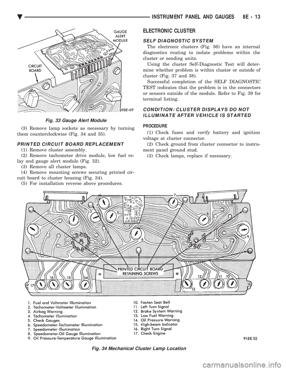
(3) Remove lamp sockets as necessary by turning
them counterclockwise (Fig. 34 and 35).
PRINTED CIRCUIT BOARD REPLACEMENT
(1) Remove cluster assembly.
(2) Remove tachometer drive module, low fuel re-
lay and gauge alert module (Fig. 32). (3) Remove all cluster lamps.
(4) Remove mounting screws securing printed cir-
cuit board to cluster housing (Fig. 34). (5) For installation reverse above procedures.
ELECTRONIC CLUSTER
SELF DIAGNOSTIC SYSTEM
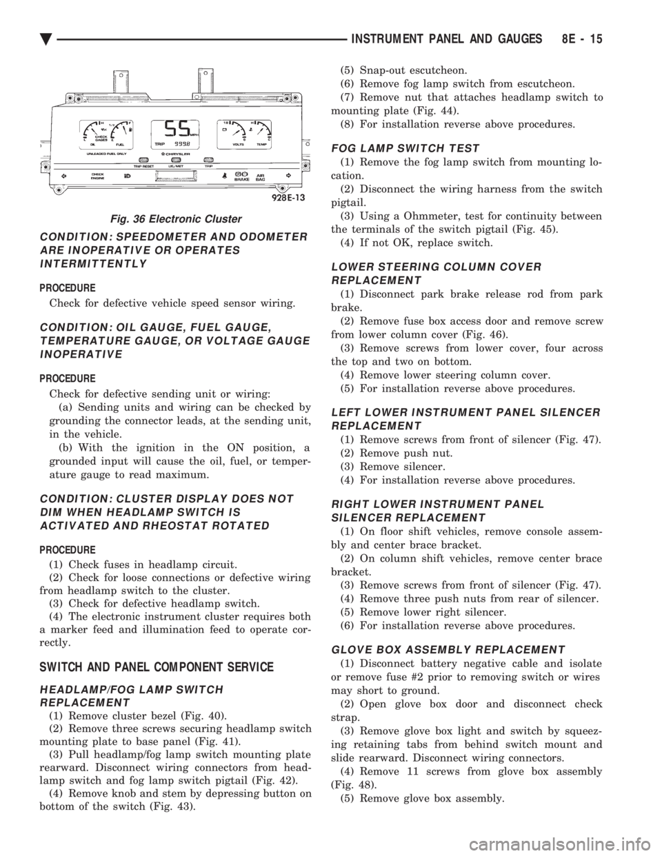
The electronic clusters (Fig. 36) have an internal
diagnostics routing to isolate problems within the
cluster or sending units. Using the cluster Self-Diagnostic Test will deter-
mine whether problem is within cluster or outside of
cluster (Fig. 37 and 38). Successful completion of the SELF DIAGNOSTIC
TEST indicates that the problem is in the connectors
or sensors outside of the module. Refer to Fig. 39 for
terminal listing.
CONDITION: CLUSTER DISPLAYS DO NOT ILLUMINATE AFTER VEHICLE IS STARTED
PROCEDURE
(1) Check fuses and verify battery and ignition
voltage at cluster connector. (2) Check ground from cluster connector to instru-
ment panel ground stud. (3) Check lamps, replace if necessary.
Fig. 34 Mechanical Cluster Lamp Location
Fig. 33 Gauge Alert Module
Ä INSTRUMENT PANEL AND GAUGES 8E - 13
Page 507 of 2438
CONDITION: SPEEDOMETER AND ODOMETER ARE INOPERATIVE OR OPERATESINTERMITTENTLY
PROCEDURE
Check for defective vehicle speed sensor wiring.
CONDITION: OIL GAUGE, FUEL GAUGE, TEMPERATURE GAUGE, OR VOLTAGE GAUGEINOPERATIVE
PROCEDURE
Check for defective sending unit or wiring: (a) Sending units and wiring can be checked by
grounding the connector leads, at the sending unit,
in the vehicle. (b) With the ignition in the ON position, a
grounded input will cause the oil, fuel, or temper-
ature gauge to read maximum.
CONDITION: CLUSTER DISPLAY DOES NOT DIM WHEN HEADLAMP SWITCH ISACTIVATED AND RHEOSTAT ROTATED
PROCEDURE
(1) Check fuses in headlamp circuit.
(2) Check for loose connections or defective wiring
from headlamp switch to the cluster. (3) Check for defective headlamp switch.
(4) The electronic instrument cluster requires both
a marker feed and illumination feed to operate cor-
rectly.
SWITCH AND PANEL COMPONENT SERVICE
HEADLAMP/FOG LAMP SWITCH REPLACEMENT
(1) Remove cluster bezel (Fig. 40).
(2) Remove three screws securing headlamp switch
mounting plate to base panel (Fig. 41). (3) Pull headlamp/fog lamp switch mounting plate
rearward. Disconnect wiring connectors from head-
lamp switch and fog lamp switch pigtail (Fig. 42). (4) Remove knob and stem by depressing button on
bottom of the switch (Fig. 43). (5) Snap-out escutcheon.
(6) Remove fog lamp switch from escutcheon.
(7) Remove nut that attaches headlamp switch to
mounting plate (Fig. 44). (8) For installation reverse above procedures.
FOG LAMP SWITCH TEST
(1) Remove the fog lamp switch from mounting lo-
cation. (2) Disconnect the wiring harness from the switch
pigtail. (3) Using a Ohmmeter, test for continuity between
the terminals of the switch pigtail (Fig. 45). (4) If not OK, replace switch.
LOWER STEERING COLUMN COVERREPLACEMENT
(1) Disconnect park brake release rod from park
brake. (2) Remove fuse box access door and remove screw
from lower column cover (Fig. 46). (3) Remove screws from lower cover, four across
the top and two on bottom. (4) Remove lower steering column cover.
(5) For installation reverse above procedures.
LEFT LOWER INSTRUMENT PANEL SILENCER REPLACEMENT
(1) Remove screws from front of silencer (Fig. 47).
(2) Remove push nut.
(3) Remove silencer.
(4) For installation reverse above procedures.
RIGHT LOWER INSTRUMENT PANEL SILENCER REPLACEMENT
(1) On floor shift vehicles, remove console assem-
bly and center brace bracket. (2) On column shift vehicles, remove center brace
bracket. (3) Remove screws from front of silencer (Fig. 47).
(4) Remove three push nuts from rear of silencer.
(5) Remove lower right silencer.
(6) For installation reverse above procedures.
GLOVE BOX ASSEMBLY REPLACEMENT
(1) Disconnect battery negative cable and isolate
or remove fuse #2 prior to removing switch or wires
may short to ground. (2) Open glove box door and disconnect check
strap. (3) Remove glove box light and switch by squeez-
ing retaining tabs from behind switch mount and
slide rearward. Disconnect wiring connectors. (4) Remove 11 screws from glove box assembly
(Fig. 48). (5) Remove glove box assembly.
Fig. 36 Electronic Cluster
Ä INSTRUMENT PANEL AND GAUGES 8E - 15
Page 526 of 2438
ELECTRONIC CLUSTER
SELF DIAGNOSTIC SYSTEM
The electronic clusters have an internal diagnostics
routing to isolate problems within the cluster or CCD
Bus. Using the cluster Self-Diagnostic Test will deter-
mine whether the problem is within the cluster or
outside of cluster (Fig. 29 and 30). Successful completion of the Self Diagnostic Test
indicates that the problem is in the CCD Bus, inter-
facing modules, connectors, or sensors outside of the
cluster. Refer to Fig. 31 for terminal listing.
CONDITION: CLUSTER DISPLAYS DO NOT ILLUMINATE AFTER VEHICLE IS STARTED
PROCEDURE
(1) Check fuses and verify battery and ignition
voltage at cluster connector. (2) Check ground from cluster connector to instru-
ment panel ground stud.
CONDITION: CLUSTER ASTERISK (*) FLASHES, CLUSTER DISPLAYS NOTINDICATING CORRECT DATA.
PROCEDURE
CCD bus problem. Use the Body Chassis Diagnos-
tic Manual to diagnose CCD Bus.
CONDITION: SPEEDOMETER AND ODOMETER ARE INOPERATIVE OR OPERATESINTERMITTENTLY
PROCEDURE
(1) If speedometer reads 0, or odometer is blank,
and cluster asterisk is flashing, use the Body Chassis
Diagnostic Manual to diagnose CCD Bus problem. (2) If cluster asterisk is not flashing, check for de-
fective vehicle speed sensor or speed sensor wiring.
CONDITION: OIL GAUGE, FUEL GAUGE, TEMPERATURE GAUGE, OR VOLTAGE GAUGEINOPERATIVE
PROCEDURE
If any gauge gives no indication and cluster aster-
isk is flashing, use the Body Chassis Manual to diag-
nose CCD Bus problem. If cluster asterisk is not flashing:
(1) Check for defective sending unit or wiring. (a) Sending units and wiring can be checked by
grounding the connector leads, at the sending unit,
in the vehicle. (b) With the ignition in the ON position, a
grounded input will cause the oil, fuel, or temper-
ature gauge to read maximum. (2) If the problem is with the oil, temperature, or
fuel gauge, check the body controller. If the problem
is with the voltage gauge, check the powertrain con-
trol module operation.
CONDITION: CLUSTER DISPLAY DOES NOT DIM WHEN HEADLAMP SWITCH ISACTIVATED AND RHEOSTAT ROTATED
PROCEDURE
If the cluster asterisk is flashing, Refer to the Body
Chassis Diagnostic Manual to diagnose the CCD Bus. If the cluster asterisk is not flashing:
(1) Check fuses in headlamp circuit.
(2) Check for loose connections or defective wiring
for headlamp switch to body controller. (3) Check for defective headlamp switch. The elec-
tronic instrument cluster receives the display inten-
sity status from the body controller via the CCD Bus.
CONDITION: SEAT BELT WARNING LAMP DOES NOT ILLUMINATE
PROCEDURE
Turn on ignition. Lamp should illuminate for six
seconds. If not: (1) Check for burned out lamp and retest.
(2) Replace cluster.
CONDITION: LOW WASHER, DOOR/DECK, OR MALFUNCTION INDICATOR (CHECK ENGINE)LAMP, DO NOT ILLUMINATE
PROCEDURE
(1) Perform cluster self-diagnostics to determine if
lamp will illuminate. If lamp does not, check for
burned out lamp, replace and retest. (2) If cluster asterisk is flashing, Refer to the Body
Chassis Diagnostic Manual to diagnose CCD Bus. (3) If cluster asterisk is not flashing:(a) For low washer fluid or door/deck, check in-
puts to body controller. (b) For malfunction indicator (check engine),
check powertrain control module operation.
CONDITION: ODOMETER DISPLAY IS BLANK. THE ODOMETER VALUE IS NO LONGERRETAINED IN THIS ELECTRONIC CLUSTER.THIS TAKES PLACE IN THE BODYCONTROLLER
PROCEDURE
(1) If cluster asterisk is flashing, Refer to the Body
Chassis Diagnostic Manual to diagnose CCD Bus. (2) If cluster asterisk is not flashing, perform clus-
ter self-diagnostics. If code 921 appears in the odom-
eter display, replace body controller for odometer
failure.
8E - 34 INSTRUMENT PANEL AND GAUGES Ä
Page 543 of 2438
Perform cluster Self Diagnostic Test to determine
whether problem is within cluster or outside of clus-
ter. Refer to Fig. 24 and 25.
Successful completion of the SELF DIAGNOSTIC
TEST indicates that the problem is in the wiring,
connectors or sensors out side of the cluster.
CLUSTER ASSEMBLY REMOVAL
The electronic cluster which is serviced as an as-
sembly is removed with the same procedure as the
conventional cluster.
CONDITION: CLUSTER DISPLAYS DO NOT ILLUMINATE AFTER VEHICLE IS STARTED
(1) Check fuses and verify battery and ignition
voltage at cluster connector. (2) Check ground from cluster connector to instru-
ment panel ground stud.
SWITCH AND PANEL COMPONENT SERVICE
HEADLAMP SWITCH
The headlamp switch is located on the left side of
the switch pod. The switch controls the headlamps,
parking lamps, fog lamps and instrument light dim- ming. If any of the switches require replacement the
entire headlamp switch assembly must be replaced
(Fig. 26 and 27).
REMOVAL
(1) Remove switch pod assembly from the instru-
ment panel. DO NOT attempt to remove instrument
cluster dimmer switch or wiper delay switch knob,
they are not removable. (2) Remove turn signal switch lever by pulling
straight out of switch pod. (3) Remove screws from bottom of switch pod.
(4) Separate inner and outer switch pod halves and
remove turn signal switch to gain access to screw. (5) Remove five inner switch pod panel screws and
3 screws from underneath the switch pod. Separate
the inner bezel from the outer bezel. (6) Remove switch mounting screws before discon-
necting linkage. (7) Disconnect switch linkage from buttons. Pull
the linkage straight up from the switch/button to dis-
engage it and remove switch.
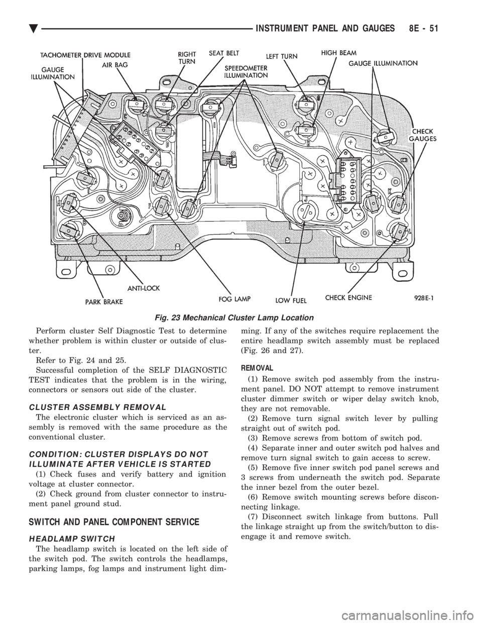
Fig. 23 Mechanical Cluster Lamp Location
Ä INSTRUMENT PANEL AND GAUGES 8E - 51
Page 632 of 2438
INTERMITTENT WINDSHIELD WIPER MOTOR AND SWITCH SERVICE PROCEDURES
INDEX
page page
Intermittent Windshield Wiper Switch Tests ..... 12
Intermittent Wipe Switch Test ............... 14
Intermittent Wiper Function Tests ............ 14
Intermittent Wiper Motor System Test ......... 12 Pulse Intermittent Windshield Wiper Controller
(PIWWC) .............................. 15
Standard Wiper Switch Test ................ 14
Wiper Switch Service Procedure ............. 15
INTERMITTENT WIPER MOTOR SYSTEM TEST
Intermittent Wiper Motor Service Procedures for
diagnosis of problems which do not involve the delay
function, refer to the Two-Speed Motor Function
Tests. The two-speed functions of all wiper motors
are identical. If a problem occurs, only in the DELAY mode, the
following tests are to be performed.
INTERMITTENT WINDSHIELD WIPER SWITCH
TESTS
WARNING: ON VEHICLES EQUIPPED WITH AIR-
BAG, SEE GROUP 8M, RESTRAINT SYSTEMS FOR
STEERING WHEEL OR COLUMN REMOVAL PROCE-
DURES.
The intermittent wipe function on AC, AG, AJ and
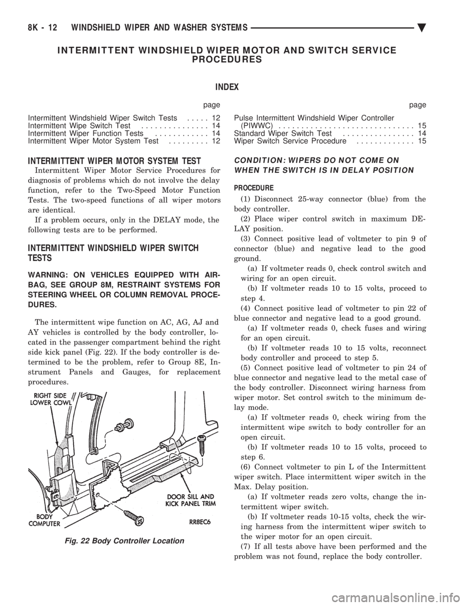
AY vehicles is controlled by the body controller, lo-
cated in the passenger compartment behind the right
side kick panel (Fig. 22). If the body controller is de-
termined to be the problem, refer to Group 8E, In-
strument Panels and Gauges, for replacement
procedures.
CONDITION: WIPERS DO NOT COME ON WHEN THE SWITCH IS IN DELAY POSITION
PROCEDURE
(1) Disconnect 25-way connector (blue) from the
body controller. (2) Place wiper control switch in maximum DE-
LAY position. (3) Connect positive lead of voltmeter to pin 9 of
connector (blue) and negative lead to the good
ground. (a) If voltmeter reads 0, check control switch and
wiring for an open circuit. (b) If voltmeter reads 10 to 15 volts, proceed to
step 4.
(4) Connect positive lead of voltmeter to pin 22 of
blue connector and negative lead to a good ground. (a) If voltmeter reads 0, check fuses and wiring
for an open circuit. (b) If voltmeter reads 10 to 15 volts, reconnect
body controller and proceed to step 5.
(5) Connect positive lead of voltmeter to pin 24 of
blue connector and negative lead to the metal case of
the body controller. Disconnect wiring harness from
wiper motor. Set control switch to the minimum de-
lay mode. (a) If voltmeter reads 0, check wiring from the
intermittent wipe switch to body controller for an
open circuit. (b) If voltmeter reads 10 to 15 volts, proceed to
step 6.
(6) Connect voltmeter to pin L of the Intermittent
wiper switch. Place intermittent wiper switch in the
Max. Delay position. (a) If voltmeter reads zero volts, change the in-
termittent wiper switch. (b) If voltmeter reads 10-15 volts, check the wir-
ing harness from the intermittent wiper switch to
the wiper motor for an open circuit.
(7) If all tests above have been performed and the
problem was not found, replace the body controller.
Fig. 22 Body Controller Location
8K - 12 WINDSHIELD WIPER AND WASHER SYSTEMS Ä
Page 643 of 2438

LAMPS
CONTENTS
page page
BULB APPLICATION TABLE ............... 38
CONCEALED HEADLAMPS ................ 27
EXTERIOR LAMP SWITCHES AND HEADLAMP ALIGNMENT ........................... 3
EXTERIOR LAMP SYSTEMS .............. 25
EXTERIOR LAMPSÐAA BODY ............. 7
EXTERIOR LAMPSÐAC BODY ............ 10 EXTERIOR LAMPSÐAG BODY
............ 14
EXTERIOR LAMPSÐAJ BODY ............ 16
EXTERIOR LAMPSÐAP BODY ............ 19
EXTERIOR LAMPSÐAY-BODY ............ 22
GENERAL INFORMATION .................. 1
ILLUMINATED ENTRY SYSTEM ........... 33
GENERAL INFORMATION
Each vehicle is equipped with lamps used for illumi-
nating and indicating purposes. A circuit must have a
good ground to be complete. Circuit ground occurs
when the lamp socket makes contact with the metal
body. On vehicles with plastic lamps, a wire between
the socket and the body makes the grounds. When changing lamp bulbs, check the socket for
corrosion. If corrosion is present, clean contacts with a
wire brush and coat the inside of the socket with
Mopar tMulti-purpose Grease or equivalent.
CAUTION: Do not touch the glass of halogen bulbs
with fingers or any possibly oily surface, reduced
bulb life will result.
BODY IDENTIFICATION
Throughout this Group, references are made to the
vehicle family or body code. To decode the vehicle
identification plates, refer to the Introduction Section
at the front of this manual.
DIAGNOSTIC PROCEDURES
Begin electrical system failure diagnosis by testing
all related fuses and circuit breakers in the fuse block
and engine compartment. When a vehicle experiences problems with the head-
lamp system, verify the condition of the battery con-
nections, charging system, headlamp bulbs, wire con-
nectors, relay, high beam dimmer switch and headlamp
switch. Refer to Wiring Diagrams manual for compo-
nent locations and circuit information.
SYMPTOM
Headlamps are dim when engine is idling of
with ignition turned OFF. Canada cars must
have lamps ON. ACTION
² Clean battery terminal clamps and posts. Refer to
Group 8B, Battery/Starter/Generator Service for
proper procedures.
² Test charging system output. Refer to Group 8A,
Battery/Starting/Charging Systems Diagnostics for
proper testing procedures.
² Test for high resistance in headlamp circuits.
² Defective headlamp bulb.
SYMPTOM
Bulbs burn out frequently.
ACTION
² Test charging system output. Refer to Group 8A,
Battery/Starting/Charging Systems Diagnostics for
proper testing procedures.
² Check for loose or corroded connector terminals or
splices in headlamp circuits. Refer to Wiring Diagrams
manual for component and splice locations.
SYMPTOM
Headlamps are dim with engine running above
idle. Canada cars must have lamps ON.
ACTION
² Test charging system output. Refer to Group 8A,
Battery/Starting/Charging Systems Diagnostics for
proper testing procedures.
² Test for high resistance in headlamp circuits.
² Defective headlamp bulb.
SYMPTOM
Headlamps flash randomly.
ACTION
² Test for poor circuit ground.
² Test for high resistance in headlamp circuits.
Ä LAMPS 8L - 1