capacities CHEVROLET EXPRESS 2004 Owners Manual
[x] Cancel search | Manufacturer: CHEVROLET, Model Year: 2004, Model line: EXPRESS, Model: CHEVROLET EXPRESS 2004Pages: 370, PDF Size: 2.42 MB
Page 1 of 370

Seats and Restraint Systems........................... 1-1
Front Seats
............................................... 1-3
Rear Seats
............................................... 1-6
Safety Belts
.............................................1-10
Child Restraints
.......................................1-31
Airbag System
.........................................1-59
Restraint System Check
............................1-70
Features and Controls..................................... 2-1
Keys
........................................................ 2-2
Doors and Locks
....................................... 2-7
Windows
.................................................2-15
Theft-Deterrent Systems
............................2-18
Starting and Operating Your Vehicle
...........2-18
Mirrors
....................................................2-29
OnStar
®System
......................................2-31
Storage Areas
.........................................2-32
Instrument Panel............................................. 3-1
Instrument Panel Overview
.......................... 3-4
Climate Controls
......................................3-18
Warning Lights, Gages, and Indicators
........3-22
Audio System(s)
.......................................3-39
Driving Your Vehicle....................................... 4-1
Your Driving, the Road, and Your Vehicle
........ 4-2
Towing
...................................................4-34Service and Appearance Care.......................... 5-1
Service
..................................................... 5-3
Fuel
......................................................... 5-5
Checking Things Under the Hood
...............5-10
All-Wheel Drive
........................................5-43
Rear Axle
...............................................5-44
Front Axle
...............................................5-44
Noise Control System
...............................5-45
Bulb Replacement
....................................5-46
Windshield Wiper Blade Replacement
.........5-51
Tires
......................................................5-52
Appearance Care
.....................................5-82
Vehicle Identication
.................................5-91
Electrical System
......................................5-92
Capacities and Specications
.....................5-97
Maintenance Schedule..................................... 6-1
Maintenance Schedule
................................ 6-2
Customer Assistance and Information.............. 7-1
Customer Assistance and Information
........... 7-2
Reporting Safety Defects
...........................7-10
Index.................................................................1
2005 Chevrolet Express Owner ManualM
Page 232 of 370
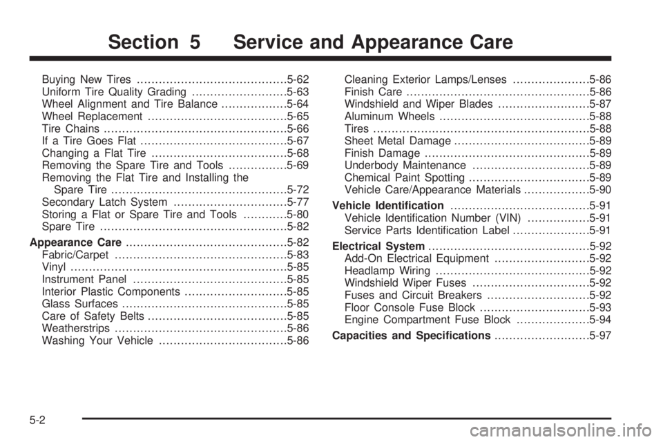
Buying New Tires.........................................5-62
Uniform Tire Quality Grading..........................5-63
Wheel Alignment and Tire Balance..................5-64
Wheel Replacement......................................5-65
Tire Chains..................................................5-66
If a Tire Goes Flat........................................5-67
Changing a Flat Tire.....................................5-68
Removing the Spare Tire and Tools................5-69
Removing the Flat Tire and Installing the
Spare Tire................................................5-72
Secondary Latch System...............................5-77
Storing a Flat or Spare Tire and Tools............5-80
Spare Tire...................................................5-82
Appearance Care............................................5-82
Fabric/Carpet...............................................5-83
Vinyl...........................................................5-85
Instrument Panel..........................................5-85
Interior Plastic Components............................5-85
Glass Surfaces.............................................5-85
Care of Safety Belts......................................5-85
Weatherstrips...............................................5-86
Washing Your Vehicle...................................5-86Cleaning Exterior Lamps/Lenses.....................5-86
Finish Care..................................................5-86
Windshield and Wiper Blades.........................5-87
Aluminum Wheels.........................................5-88
Tires...........................................................5-88
Sheet Metal Damage.....................................5-89
Finish Damage.............................................5-89
Underbody Maintenance................................5-89
Chemical Paint Spotting.................................5-89
Vehicle Care/Appearance Materials..................5-90
Vehicle Identication......................................5-91
Vehicle Identication Number (VIN).................5-91
Service Parts Identication Label.....................5-91
Electrical System............................................5-92
Add-On Electrical Equipment..........................5-92
Headlamp Wiring..........................................5-92
Windshield Wiper Fuses................................5-92
Fuses and Circuit Breakers............................5-92
Floor Console Fuse Block..............................5-93
Engine Compartment Fuse Block....................5-94
Capacities and Specications..........................5-97
Section 5 Service and Appearance Care
5-2
Page 244 of 370

When to Add Engine Oil
If the oil is at or below the cross-hatched area at the tip
of the dipstick, then you will need to add at least one
quart of oil. But you must use the right kind. This section
explains what kind of oil to use. For engine oil
crankcase capacity, seeCapacities and Specications
on page 5-97.
Notice:Do not add too much oil. If your engine has
so much oil that the oil level gets above the
cross-hatched area that shows the proper operating
range, your engine could be damaged.SeeEngine Compartment
Overview on page 5-12for
the location of the
engine oil ll cap.
Be sure to add enough oil to put the level somewhere in
the proper operating range. Push the dipstick all the
way back in when you are through.
What Kind of Engine Oil to Use
Look for two things:
GM6094M
Your vehicle’s engine requires oil meeting GM
Standard GM6094M. You should look for and use
only an oil that meets GM Standard GM6094M.
5-14
Page 289 of 370

A Tire and Loading Information label is attached to the
vehicle’s center pillar (B-pillar), below the driver’s
door latch. This label shows your vehicle’s original
equipment tires and the correct ination pressures for
your tires when they are cold. The recommended
cold tire ination pressure, shown on the label, is the
minimum amount of air pressure needed to support your
vehicle’s maximum load carrying capacity.
For additional information regarding how much weight
your vehicle can carry, and an example of the tire
and loading information label, seeLoading Your Vehicle
on page 4-29. How you load your vehicle affects
vehicle handling and ride comfort, never load your
vehicle with more weight than it was designed to carry.
When to Check
Check your tires once a month or more.
Also, check the tire pressure of the spare tire.
How to Check
Use a good quality pocket-type gage to check tire
pressure. You cannot tell if your tires are properly
inated simply by looking at them. Radial tires may
look properly inated even when they’re underinated.
Check the tire’s ination pressure when the tires
are cold. Cold means your vehicle has been sitting
for at least three hours or driven no more than
1 mile (1.6 km).Remove the valve cap from the tire valve stem. Press
the tire gage rmly onto the valve to get a pressure
measurement. If the cold tire ination pressure matches
the recommended pressure on the tire and loading
information label, no further adjustment is necessary. If
the pressure is low, add air until you reach the
recommended amount.
If you overll the tire, release air by pushing on the
metal stem in the center of the tire valve. Recheck the
tire pressure with the tire gage.
Be sure to put the valve caps back on the valve stems.
They help prevent leaks by keeping out dirt and
moisture.
Dual Tire Operation
When the vehicle is new, or whenever a wheel,
wheel bolt or wheel nut is replaced, check the wheel
nut torque after 100, 1,000 and 6,000 miles
(160, 1 600 and 10 000 km) of driving. For proper wheel
nut tightening information, see “Removing the Flat
Tire and Installing the Spare Tire” later in this section,
underChanging a Flat Tire on page 5-68. Also see
“Wheel Nut Torque” underCapacities and Specications
on page 5-97.
5-59
Page 291 of 370

If your vehicle has dual rear wheels, always use one of
the correct rotation patterns shown here when rotating
your tires.
When you install dual wheels, be sure that vent holes in
the inner and outer wheels on each side are lined up.
After the tires have been rotated, adjust the front
and rear ination pressures as shown on the Tire and
Loading Information label. SeeLoading Your Vehicle on
page 4-29. Make certain that all wheel nuts are
properly tightened. See “Wheel Nut Torque” under
Capacities and Specications on page 5-97.
{CAUTION:
Rust or dirt on a wheel, or on the parts to
which it is fastened, can make wheel nuts
become loose after a time. The wheel could
come off and cause an accident. When you
change a wheel, remove any rust or dirt from
places where the wheel attaches to the vehicle.
In an emergency, you can use a cloth or a
paper towel to do this; but be sure to use a
scraper or wire brush later, if you need to, to
get all the rust or dirt off. SeeChanging a Flat
Tire on page 5-68. Dual Rear Wheels
5-61
Page 295 of 370

Wheel Replacement
Replace any wheel that is bent, cracked, or badly rusted
or corroded. If wheel nuts keep coming loose, the
wheel, wheel bolts and wheel nuts should be replaced.
If the wheel leaks air, replace it (except some
aluminum wheels, which can sometimes be repaired).
See your dealer if any of these conditions exist.
Your dealer will know the kind of wheel you need.
Each new wheel should have the same load-carrying
capacity, diameter, width, offset and be mounted
the same way as the one it replaces.
If you need to replace any of your wheels, wheel
bolts or wheel nuts, replace them only with new
GM original equipment parts. This way, you will be sure
to have the right wheel, wheel bolts and wheel nuts
for your vehicle.{CAUTION:
Using the wrong replacement wheels, wheel
bolts or wheel nuts on your vehicle can be
dangerous. It could affect the braking and
handling of your vehicle, make your tires lose
air and make you lose control. You could have
a collision in which you or others could be
injured. Always use the correct wheel, wheel
bolts and wheel nuts for replacement.
Notice:The wrong wheel can also cause problems
with bearing life, brake cooling, speedometer or
odometer calibration, headlamp aim, bumper height,
vehicle ground clearance and tire or tire chain
clearance to the body and chassis.
Whenever a wheel, wheel bolt or wheel nut is replaced
on a dual wheel setup, check the wheel nut torque
after 100, 1,000 and 6,000 miles (160, 1 600 and
10 000 km) of driving. For proper torque, see “Wheel Nut
Torque” underCapacities and Specications on
page 5-97.
SeeChanging a Flat Tire on page 5-68for more
information.
5-65
Page 307 of 370

{CAUTION:
Incorrect wheel nuts or improperly tightened
wheel nuts can cause the wheel to come loose
and even come off. This could lead to an
accident. Be sure to use the correct wheel
nuts. If you have to replace them, be sure to
get new GM original equipment wheel nuts.
Stop somewhere as soon as you can and have
the nuts tightened with a torque wrench to the
proper torque specication. SeeCapacities
and Specifications on page 5-97for wheel nut
torque specication.
Notice:Improperly tightened wheel nuts can lead
to brake pulsation and rotor damage. To avoid
expensive brake repairs, evenly tighten the wheel
nuts in the proper sequence and to the proper
torque specication. SeeCapacities and
Specifications on page 5-97for the wheel nut
torque specication.9. Tighten the nuts rmly in a crisscross sequence as
shown. Turn the wheel wrench clockwise.
10. Put the wheel cover or the center cap and plastic
wheel nut caps back on. Remove any wheel
blocks.
Secondary Latch System
Your vehicle has an underbody mounted tire hoist
assembly equipped with a secondary latch system. It is
designed to stop the spare tire from suddenly falling
off the vehicle if the cable holding the spare tire is
damaged. For the secondary latch to work, the tire must
be stowed with the valve stem pointing down.
5-77
Page 327 of 370

Capacities and Specications
The following approximate capacities are given in English and metric conversions. SeeRecommended Fluids and
Lubricants on page 6-13for more information. When adding, be sure to ll to the appropriate level or as
recommended in this manual.
See refrigerant charge label under the hood for charge capacity information and requirements.
ApplicationCapacities
English Metric
Air Conditioning Refrigerant R134a
Front A/C
Front and Rear A/C1.8 lbs
3.1 lbs0.81 kg
1.41 kg
Cooling System
4300 V6
4800 V8, 5300 V8
6000 V811.0 quarts
13.4 quarts
14.8 quarts10.4 L
12.7 L
14.0 L
Cooling System with Rear Heat
4300 V6
4800 V8, 5300 V8
6000 V814.0 quarts
16.4 quarts
17.8 quarts13.2 L
15.5 L
17.0 L
Engine Oil with Filter
4300 V6
4800 V, 5300 V8
6000 V84.5 quarts
6.0 quarts
6.0 quarts4.3 L
5.7 L
5.7 L
5-97
Page 328 of 370

ApplicationCapacities
English Metric
Fuel Tank
Standard Tank (Passenger and Cargo)
Standard Tank (Cab and Chassis)
Optional Tank (Cab and Chassis)*
* 159 inch (4 039 mm) wheelbase or 177 inch (4 496 mm)
wheel base only31.0 gallons
33.0 gallons
57.0 gallons117.3 L
124.9 L
215.7 L
Wheel Nut Torque 140 ft lb 190Y
All capacities are approximate. When adding, be sure to ll to the approximate level, as recommended in this
manual. Recheck uid level after lling.
Engine Specications
Engine VIN Code Transmission Spark Plug Gap
VORTEC™ 4300 V6 W Automatic 0.040 inches (1.01 mm)
VORTEC™ 4800 V8 V Automatic 0.040 inches (1.01 mm)
VORTEC™ 5300 V8 T Automatic 0.040 inches (1.01 mm)
VORTEC™ 6000 V8 U Automatic 0.040 inches (1.01 mm)
5-98
Page 338 of 370

Owner Checks and Services
These owner checks and services should be performed
at the intervals specied to help ensure the safety,
dependability and emission control performance of your
vehicle. Your GM Goodwrench dealer can assist you
with these checks and services.
Be sure any necessary repairs are completed at once.
Whenever any uids or lubricants are added to your
vehicle, make sure they are the proper ones, as shown
inRecommended Fluids and Lubricants on page 6-13.
At the First 100, 1,000 and
6,000 Miles (160, 1 600
and 10 000km)
For vehicles with dual wheels, check dual wheel nut
torque. For proper torque, seeCapacities and
Specications on page 5-97.
At Each Fuel Fill
It is important to perform these underhood checks at
each fuel ll.
Engine Oil Level Check
Check the engine oil level and add the proper oil if
necessary. SeeEngine Oil on page 5-13for further
details.
Notice:It is important to check your oil regularly
and keep it at the proper level. Failure to keep your
engine oil at the proper level can cause damage
to your engine not covered by your warranty.
Engine Coolant Level Check
Check the engine coolant level and add
DEX-COOL®coolant mixture if necessary. SeeEngine
Coolant on page 5-22for further details.
Windshield Washer Fluid Level Check
Check the windshield washer uid level in the windshield
washer tank and add the proper uid if necessary.
At Least Once a Month
Tire Ination Check
Visually inspect your tires and make sure tires are
inated to the correct pressures. Do not forget to check
your spare tire. SeeTires on page 5-52for further
details. Check to make sure the spare tire is stored
securely. Push, pull and then try to turn the spare tire. If
it moves, tighten it. SeeChanging a Flat Tire on
page 5-68.
6-10