AUX CHEVROLET KODIAK 2004 Owners Manual
[x] Cancel search | Manufacturer: CHEVROLET, Model Year: 2004, Model line: KODIAK, Model: CHEVROLET KODIAK 2004Pages: 366, PDF Size: 6.87 MB
Page 115 of 366
A. Air Outlets. SeeOutlet Adjustment on page 3-22.
B. Instrument Panel Cluster. SeeInstrument Panel
Cluster on page 3-24.
C. Shift Lever. SeeStarting Your Gasoline Engine on
page 2-12,Starting Your Diesel Engine on page 2-14
andStarting Your DURAMAX™ Diesel Engine on
page 2-19.
D. Air Brake Controls. See ‘‘Air Brake’’ underParking
on page 2-33.
E. Auxiliary Gages. SeeWarning Lights, Gages, and
Indicators on page 3-23.
F. Exterior Lamp Control. SeeExterior Lamps on
page 3-13.
G. Turn Signal/Multifunction Lever. SeeTurn
Signal/Multifunction Lever on page 3-7.
H. Hazard Warning Flashers Button. SeeHazard
Warning Flashers on page 3-5.
I. Audio System(s). SeeAudio System(s) on
page 3-45.
J. Climate Controls. SeeClimate Control System on
page 3-19.
K. Instrument Panel Switchbank. SeeInstrument Panel
Switchbank on page 3-16.
L. Air Bag Off Switch. SeeAir Bag Off Switch on
page 1-55.
M. Accessory Power Outlets. SeeAccessory Power
Outlets on page 3-17.Hazard Warning Flashers
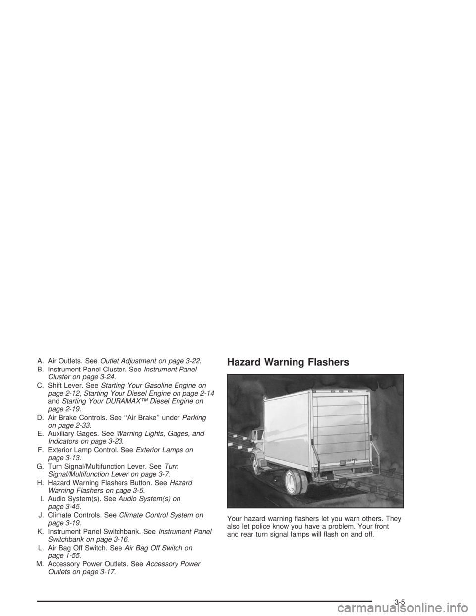
Your hazard warning flashers let you warn others. They
also let police know you have a problem. Your front
and rear turn signal lamps will flash on and off.
3-5
Page 127 of 366
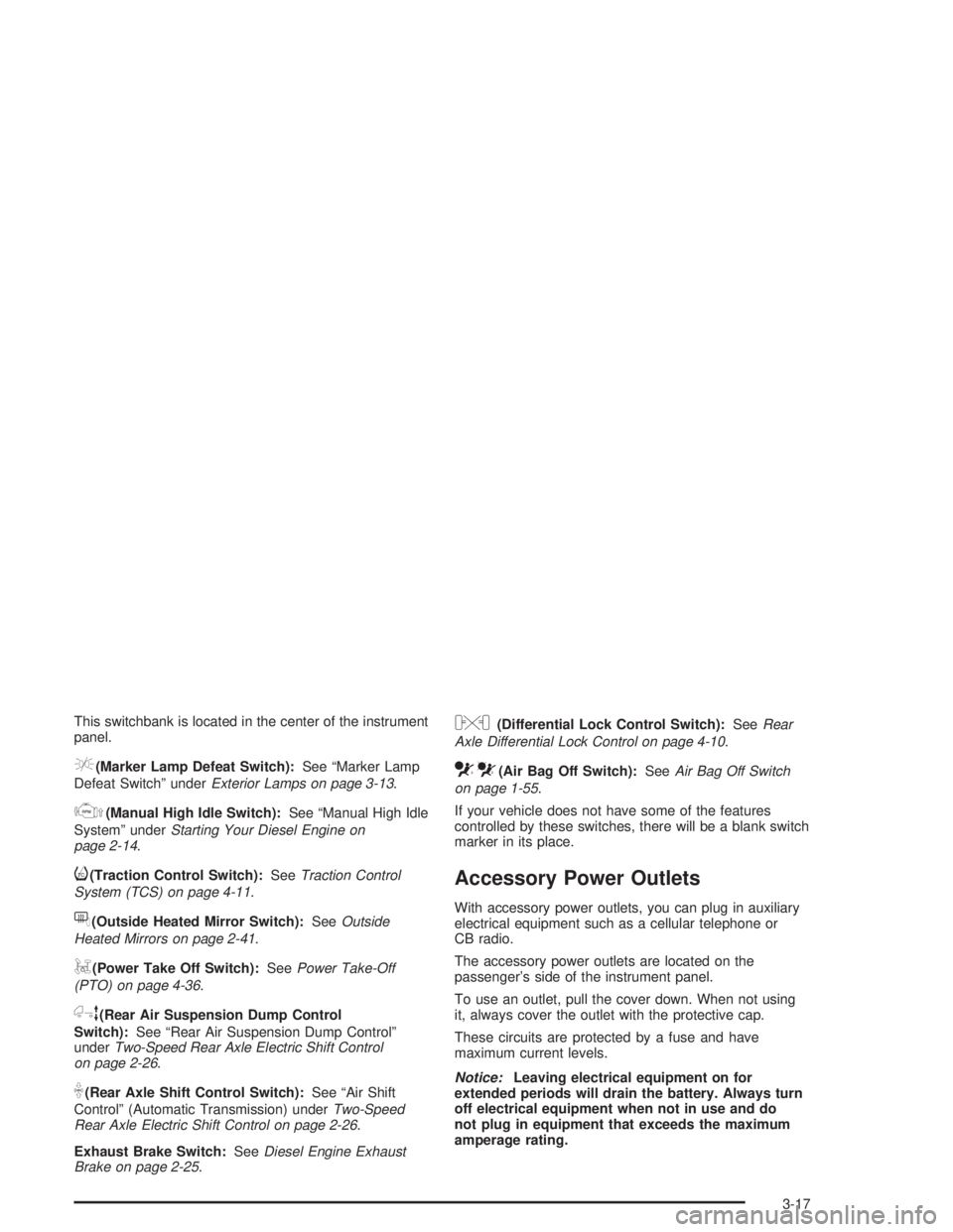
This switchbank is located in the center of the instrument
panel.
e(Marker Lamp Defeat Switch):See “Marker Lamp
Defeat Switch” underExterior Lamps on page 3-13.
j(Manual High Idle Switch):See “Manual High Idle
System” underStarting Your Diesel Engine on
page 2-14.
i(Traction Control Switch):SeeTraction Control
System (TCS) on page 4-11.
f(Outside Heated Mirror Switch):SeeOutside
Heated Mirrors on page 2-41.
g(Power Take Off Switch):SeePower Take-Off
(PTO) on page 4-36.
h(Rear Air Suspension Dump Control
Switch):See “Rear Air Suspension Dump Control”
underTwo-Speed Rear Axle Electric Shift Control
on page 2-26.
k(Rear Axle Shift Control Switch):See “Air Shift
Control” (Automatic Transmission) underTwo-Speed
Rear Axle Electric Shift Control on page 2-26.
Exhaust Brake Switch:SeeDiesel Engine Exhaust
Brake on page 2-25.
l(Differential Lock Control Switch):SeeRear
Axle Differential Lock Control on page 4-10.
cd(Air Bag Off Switch):SeeAir Bag Off Switch
on page 1-55.
If your vehicle does not have some of the features
controlled by these switches, there will be a blank switch
marker in its place.
Accessory Power Outlets
With accessory power outlets, you can plug in auxiliary
electrical equipment such as a cellular telephone or
CB radio.
The accessory power outlets are located on the
passenger’s side of the instrument panel.
To use an outlet, pull the cover down. When not using
it, always cover the outlet with the protective cap.
These circuits are protected by a fuse and have
maximum current levels.
Notice:Leaving electrical equipment on for
extended periods will drain the battery. Always turn
off electrical equipment when not in use and do
not plug in equipment that exceeds the maximum
amperage rating.
3-17
Page 140 of 366
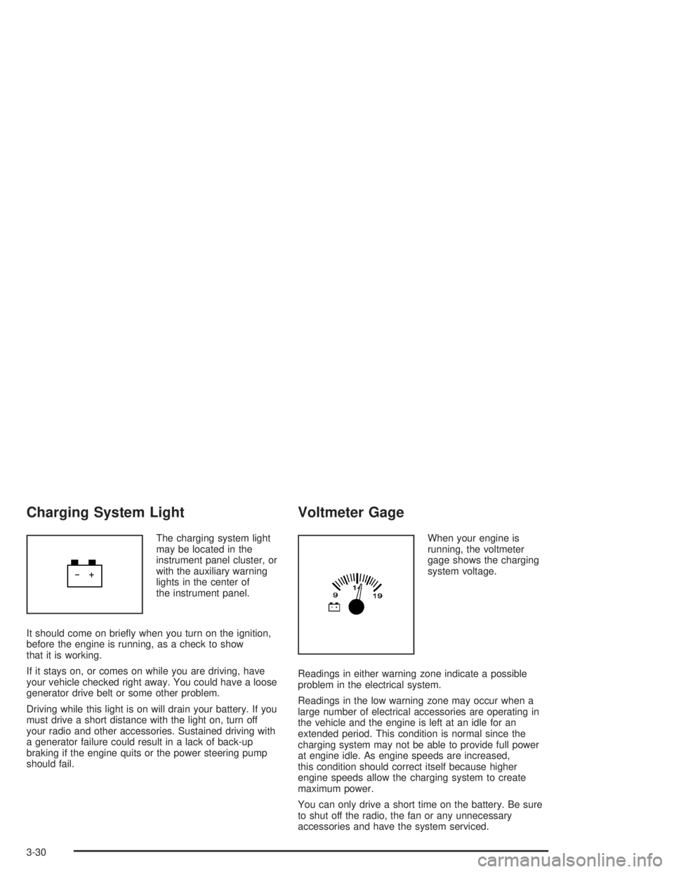
Charging System Light
The charging system light
may be located in the
instrument panel cluster, or
with the auxiliary warning
lights in the center of
the instrument panel.
It should come on briefly when you turn on the ignition,
before the engine is running, as a check to show
that it is working.
If it stays on, or comes on while you are driving, have
your vehicle checked right away. You could have a loose
generator drive belt or some other problem.
Driving while this light is on will drain your battery. If you
must drive a short distance with the light on, turn off
your radio and other accessories. Sustained driving with
a generator failure could result in a lack of back-up
braking if the engine quits or the power steering pump
should fail.
Voltmeter Gage
When your engine is
running, the voltmeter
gage shows the charging
system voltage.
Readings in either warning zone indicate a possible
problem in the electrical system.
Readings in the low warning zone may occur when a
large number of electrical accessories are operating in
the vehicle and the engine is left at an idle for an
extended period. This condition is normal since the
charging system may not be able to provide full power
at engine idle. As engine speeds are increased,
this condition should correct itself because higher
engine speeds allow the charging system to create
maximum power.
You can only drive a short time on the battery. Be sure
to shut off the radio, the fan or any unnecessary
accessories and have the system serviced.
3-30
Page 141 of 366
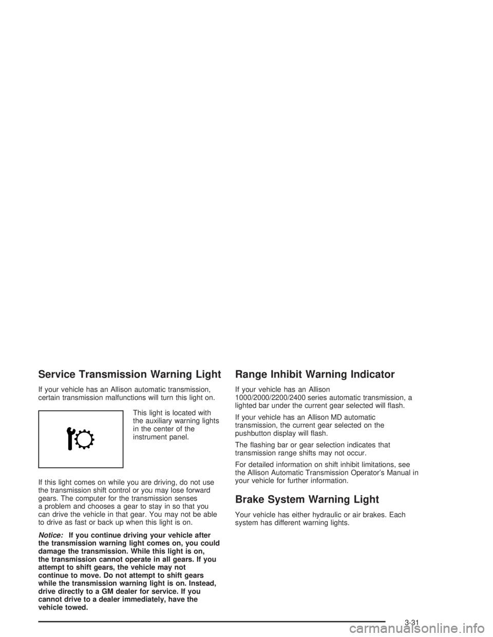
Service Transmission Warning Light
If your vehicle has an Allison automatic transmission,
certain transmission malfunctions will turn this light on.
This light is located with
the auxiliary warning lights
in the center of the
instrument panel.
If this light comes on while you are driving, do not use
the transmission shift control or you may lose forward
gears. The computer for the transmission senses
a problem and chooses a gear to stay in so that you
can drive the vehicle in that gear. You may not be able
to drive as fast or back up when this light is on.
Notice:If you continue driving your vehicle after
the transmission warning light comes on, you could
damage the transmission. While this light is on,
the transmission cannot operate in all gears. If you
attempt to shift gears, the vehicle may not
continue to move. Do not attempt to shift gears
while the transmission warning light is on. Instead,
drive directly to a GM dealer for service. If you
cannot drive to a dealer immediately, have the
vehicle towed.
Range Inhibit Warning Indicator
If your vehicle has an Allison
1000/2000/2200/2400 series automatic transmission, a
lighted bar under the current gear selected will flash.
If your vehicle has an Allison MD automatic
transmission, the current gear selected on the
pushbutton display will flash.
The flashing bar or gear selection indicates that
transmission range shifts may not occur.
For detailed information on shift inhibit limitations, see
the Allison Automatic Transmission Operator’s Manual in
your vehicle for further information.
Brake System Warning Light
Your vehicle has either hydraulic or air brakes. Each
system has different warning lights.
3-31
Page 296 of 366
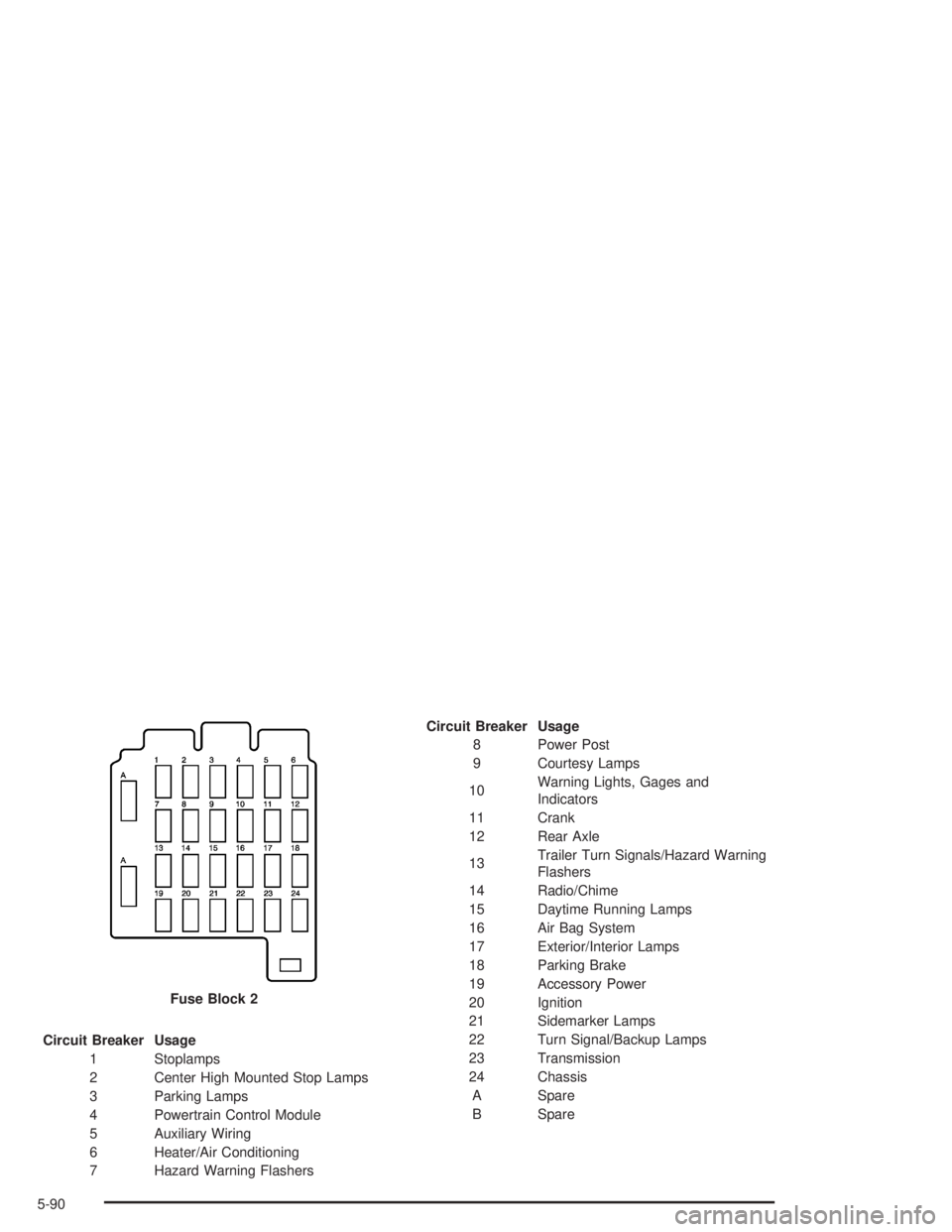
Circuit Breaker Usage
1 Stoplamps
2 Center High Mounted Stop Lamps
3 Parking Lamps
4 Powertrain Control Module
5 Auxiliary Wiring
6 Heater/Air Conditioning
7 Hazard Warning FlashersCircuit Breaker Usage
8 Power Post
9 Courtesy Lamps
10Warning Lights, Gages and
Indicators
11 Crank
12 Rear Axle
13Trailer Turn Signals/Hazard Warning
Flashers
14 Radio/Chime
15 Daytime Running Lamps
16 Air Bag System
17 Exterior/Interior Lamps
18 Parking Brake
19 Accessory Power
20 Ignition
21 Sidemarker Lamps
22 Turn Signal/Backup Lamps
23 Transmission
24 Chassis
A Spare
B Spare Fuse Block 2
5-90
Page 302 of 366
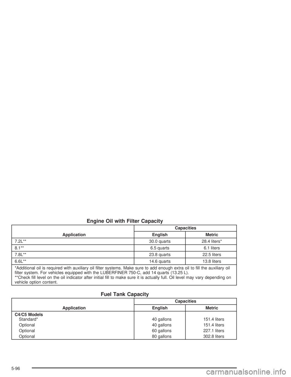
Engine Oil with Filter Capacity
ApplicationCapacities
English Metric
7.2L** 30.0 quarts 28.4 liters*
8.1** 6.5 quarts 6.1 liters
7.8L** 23.8 quarts 22.5 liters
6.6L** 14.6 quarts 13.8 liters
*Additional oil is required with auxiliary oil filter systems. Make sure to add enough extra oil to fill the auxiliary oil
filter system. For vehicles equipped with the LUBERFINER 750-C, add 14 quarts (13.25 L).
**Check fill level on the oil indicator after initial fill to make sure it is actually full. Oil level may vary depending on
vehicle option content.
Fuel Tank Capacity
ApplicationCapacities
English Metric
C4/C5 Models
Standard*
Optional
Optional
Optional40 gallons
40 gallons
60 gallons
80 gallons151.4 liters
151.4 liters
227.1 liters
302.8 liters
5-96