fuses CHEVROLET MALIBU 2020 Owner's Manual
[x] Cancel search | Manufacturer: CHEVROLET, Model Year: 2020, Model line: MALIBU, Model: CHEVROLET MALIBU 2020Pages: 358, PDF Size: 3.27 MB
Page 4 of 358
Chevrolet Malibu Owner Manual (GMNA-Localizing-U.S./Canada/Mexico-
13555849) - 2020 - CRC - 8/16/19
Introduction 3
{Danger
Danger indicates a hazard with a
high level of risk which will result
in serious injury or death.
{Warning
Warning indicates a hazard that
could result in injury or death.
Caution
Caution indicates a hazard that
could result in property or vehicle
damage.
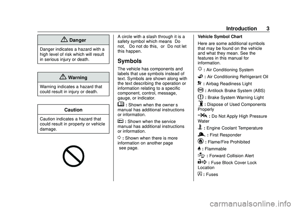
A circle with a slash through it is a
safety symbol which means“Do
not,” “Do not do this,” or“Do not let
this happen.”
Symbols
The vehicle has components and
labels that use symbols instead of
text. Symbols are shown along with
the text describing the operation or
information relating to a specific
component, control, message,
gauge, or indicator.
M: Shown when the owner ’s
manual has additional instructions
or information.
*: Shown when the service
manual has additional instructions
or information.
0: Shown when there is more
information on another page —
“see page.” Vehicle Symbol Chart
Here are some additional symbols
that may be found on the vehicle
and what they mean. See the
features in this manual for
information.
u:
Air Conditioning System
G:Air Conditioning Refrigerant Oil
9:Airbag Readiness Light
!:Antilock Brake System (ABS)
$:Brake System Warning Light
9:Dispose of Used Components
Properly
P: Do Not Apply High Pressure
Water
B: Engine Coolant Temperature
g: First Responder
_:Flame/Fire Prohibited
H:Flammable
[:Forward Collision Alert
R: Fuse Block Cover Lock
Location
+: Fuses
Page 92 of 358
Chevrolet Malibu Owner Manual (GMNA-Localizing-U.S./Canada/Mexico-
13555849) - 2020 - CRC - 8/16/19
Instruments and Controls 91
Compass
The vehicle may have a compass
display on the Driver Information
Center (DIC). The compass receives
its heading and other information
from the Global Positioning
System (GPS) antenna, StabiliTrak/
Electronic Stability Control (ESC),
and vehicle speed information.
The compass system is designed to
operate for a certain number of
miles or degrees of turn before
needing a signal from the GPS
satellites. When the compass
display shows CAL, drive the
vehicle for a short distance in an
open area where it can receive a
GPS signal. The compass system
will automatically determine when a
GPS signal is restored and provide
a heading again.
Clock
The time and date for the clock can
be set using the infotainment
system. See“Time/Date”in
“System” under“Settings” in the
infotainment manual.
Power Outlets
Power Outlet 12-Volt Direct
Current
The accessory power outlets can be
used to plug in electrical equipment,
such as a cell phone or MP3 player.
There are two accessory power
outlets:
. One on the center stack below
the climate control system
. One on the rear of the center
console
The outlet is powered when the
ignition is on or in ACC/
ACCESSORY, or until the driver
door is opened within 10 minutes of
turning off the vehicle. See Retained
Accessory Power (RAP) 0160.
Open the protective cover to use the
accessory power outlet.
Certain electrical accessories may
not be compatible with the
accessory power outlets and could
overload vehicle or adapter fuses.
If there is a problem, see your
dealer. When adding electrical equipment,
be sure to follow the installation
instructions included with the
equipment. See
Add-On Electrical
Equipment 0210.
Caution
Hanging heavy equipment from
the power outlet can cause
damage not covered by the
vehicle warranty. The power
outlets are designed for
accessory power plugs only, such
as cell phone charge cords.
Always unplug electrical equipment
when not in use and do not plug in
equipment that exceeds the
maximum 20 amps rating.
Power Outlet 110/120-Volt
Alternating Current
If equipped, this power outlet can be
used to plug in electrical equipment
that uses a maximum limit of 150
watts.
Page 130 of 358
Chevrolet Malibu Owner Manual (GMNA-Localizing-U.S./Canada/Mexico-
13555849) - 2020 - CRC - 8/16/19
Lighting 129
Turn and Lane-Change
Signals
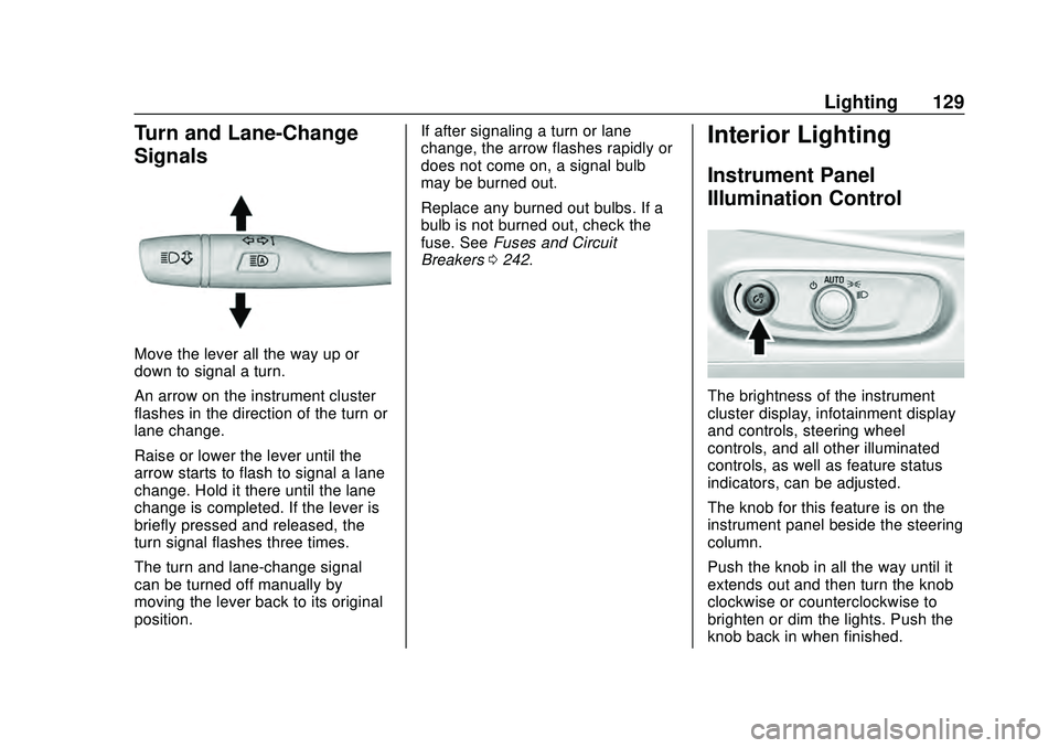
Move the lever all the way up or
down to signal a turn.
An arrow on the instrument cluster
flashes in the direction of the turn or
lane change.
Raise or lower the lever until the
arrow starts to flash to signal a lane
change. Hold it there until the lane
change is completed. If the lever is
briefly pressed and released, the
turn signal flashes three times.
The turn and lane-change signal
can be turned off manually by
moving the lever back to its original
position.If after signaling a turn or lane
change, the arrow flashes rapidly or
does not come on, a signal bulb
may be burned out.
Replace any burned out bulbs. If a
bulb is not burned out, check the
fuse. See
Fuses and Circuit
Breakers 0242.
Interior Lighting
Instrument Panel
Illumination Control
The brightness of the instrument
cluster display, infotainment display
and controls, steering wheel
controls, and all other illuminated
controls, as well as feature status
indicators, can be adjusted.
The knob for this feature is on the
instrument panel beside the steering
column.
Push the knob in all the way until it
extends out and then turn the knob
clockwise or counterclockwise to
brighten or dim the lights. Push the
knob back in when finished.
Page 212 of 358
Chevrolet Malibu Owner Manual (GMNA-Localizing-U.S./Canada/Mexico-
13555849) - 2020 - CRC - 8/21/19
Vehicle Care 211
Vehicle Care
General Information
General Information . . . . . . . . . . 212
California Proposition65 Warning . . . . . . . . . . . . . . . . . 213
California Perchlorate Materials Requirements . . . . . 213
Accessories and Modifications . . . . . . . . . . . . . . . . 213
Vehicle Checks
Doing Your OwnService Work . . . . . . . . . . . . . . . 214
Hood . . . . . . . . . . . . . . . . . . . . . . . . . 214
Engine Compartment Overview . . . . . . . . . . . . . . . . . . . . 216
Engine Oil . . . . . . . . . . . . . . . . . . . . 219
Engine Oil Life System . . . . . . . 221
Automatic Transmission Fluid . . . . . . . . . . . . . . . . . . . . . . . . 222
Engine Air Filter Life System . . . . . . . . . . . . . . . . . . . . . . 223
Engine Air Cleaner/Filter . . . . . . 223
Cooling System . . . . . . . . . . . . . . 225
Engine Overheating . . . . . . . . . . 228
Washer Fluid . . . . . . . . . . . . . . . . . 229
Brakes . . . . . . . . . . . . . . . . . . . . . . . 230
Brake Fluid . . . . . . . . . . . . . . . . . . . 231 Battery - North America . . . . . . 232
Starter Switch Check . . . . . . . . . 234
Automatic Transmission Shift
Lock Control Function
Check . . . . . . . . . . . . . . . . . . . . . . . 234
Park Brake and P (Park) Mechanism Check . . . . . . . . . . 235
Wiper Blade Replacement . . . . 235
Windshield Replacement . . . . . 236
Gas Strut(s) . . . . . . . . . . . . . . . . . . 236
Headlamp Aiming
Front Headlamp Aiming . . . . . . 237
Bulb Replacement
Bulb Replacement . . . . . . . . . . . . 238
Halogen Bulbs . . . . . . . . . . . . . . . . 238
LED Lighting . . . . . . . . . . . . . . . . . 238
Headlamps, Front Turn Signal, Sidemarker, and Parking
Lamps . . . . . . . . . . . . . . . . . . . . . . 238
Taillamps, Turn Signal, Stoplamps, and Back-Up
Lamps (LS and LT) . . . . . . . . . . 239
Taillamps, Turn Signal, Stoplamps, and Back-Up
Lamps (LT and Premier) . . . . . 240
License Plate Lamp . . . . . . . . . . 240
Electrical System
High Voltage Devices and Wiring . . . . . . . . . . . . . . . . . . . . . . . 241
Electrical System Overload . . . 242
Fuses and Circuit Breakers . . . 242
Engine Compartment Fuse Block . . . . . . . . . . . . . . . . . . . . . . . . 243
Instrument Panel Fuse Block . . . . . . . . . . . . . . . . . . . . . . . . 247
Wheels and Tires
Tires . . . . . . . . . . . . . . . . . . . . . . . . . . 250
All-Season Tires . . . . . . . . . . . . . . 251
Winter Tires . . . . . . . . . . . . . . . . . . 251
Low-Profile Tires . . . . . . . . . . . . . 251
Summer Tires . . . . . . . . . . . . . . . . 252
Tire Sidewall Labeling . . . . . . . . 252
Tire Designations . . . . . . . . . . . . . 254
Tire Terminology andDefinitions . . . . . . . . . . . . . . . . . . 255
Tire Pressure . . . . . . . . . . . . . . . . . 257
Tire Pressure for High-Speed Operation . . . . . . . . . . . . . . . . . . . 259
Tire Pressure Monitor System . . . . . . . . . . . . . . . . . . . . . . 259
Tire Pressure Monitor Operation . . . . . . . . . . . . . . . . . . . 260
Tire Inspection . . . . . . . . . . . . . . . . 264
Tire Rotation . . . . . . . . . . . . . . . . . 265
Page 243 of 358
Chevrolet Malibu Owner Manual (GMNA-Localizing-U.S./Canada/Mexico-
13555849) - 2020 - CRC - 8/21/19
242 Vehicle Care
Electrical System
Overload
The vehicle has fuses and circuit
breakers to protect against an
electrical system overload.
When the current electrical load is
too heavy, the circuit breaker opens
and closes, protecting the circuit
until the current load returns to
normal or the problem is fixed. This
greatly reduces the chance of circuit
overload and fire caused by
electrical problems.
Fuses and circuit breakers protect
power devices in the vehicle.
Replace a bad fuse with a new one
of the identical size and rating.
If there is a problem on the road and
a fuse needs to be replaced, the
same amperage fuse can be
borrowed. Choose some feature of
the vehicle that is not needed and
replace it as soon as possible.
Headlamp Wiring
An electrical overload may cause
the lamps to go on and off, or in
some cases to remain off. Have the
headlamp wiring checked
right away.
Windshield Wipers
If the wiper motor overheats due to
heavy snow or ice, the windshield
wipers will stop until the motor cools
and will then restart.
Although the circuit is protected
from electrical overload, overload
due to heavy snow or ice may
cause wiper linkage damage.
Always clear ice and heavy snow
from the windshield before using the
windshield wipers.
If the overload is caused by an
electrical problem and not snow or
ice, be sure to get it fixed.
Fuses and Circuit
Breakers
The wiring circuits in the vehicle are
protected from short circuits by a
combination of fuses and circuitbreakers. This greatly reduces the
chance of damage caused by
electrical problems.
{Danger
Fuses and circuit breakers are
marked with their ampere rating.
Do not exceed the
specified amperage rating when
replacing fuses and circuit
breakers. Use of an oversized
fuse or circuit breaker can result
in a vehicle fire. You and others
could be seriously injured or
killed.
To check a fuse, look at the
silver-colored band inside the fuse.
If the band is broken or melted,
replace the fuse. Be sure to replace
a bad fuse with a new one of the
identical size and rating.
Fuses of the same amperage can
be temporarily borrowed from
another fuse location, if a fuse goes
out. Replace the fuse as soon as
possible.
Page 244 of 358
Chevrolet Malibu Owner Manual (GMNA-Localizing-U.S./Canada/Mexico-
13555849) - 2020 - CRC - 8/21/19
Vehicle Care 243
Engine Compartment
Fuse Block
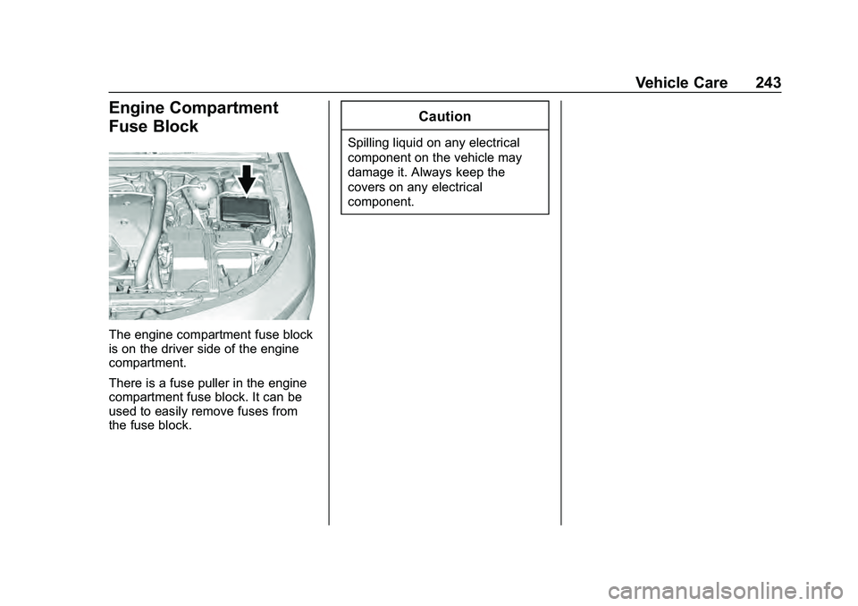
The engine compartment fuse block
is on the driver side of the engine
compartment.
There is a fuse puller in the engine
compartment fuse block. It can be
used to easily remove fuses from
the fuse block.
Caution
Spilling liquid on any electrical
component on the vehicle may
damage it. Always keep the
covers on any electrical
component.
Page 246 of 358
Chevrolet Malibu Owner Manual (GMNA-Localizing-U.S./Canada/Mexico-
13555849) - 2020 - CRC - 8/21/19
Vehicle Care 245
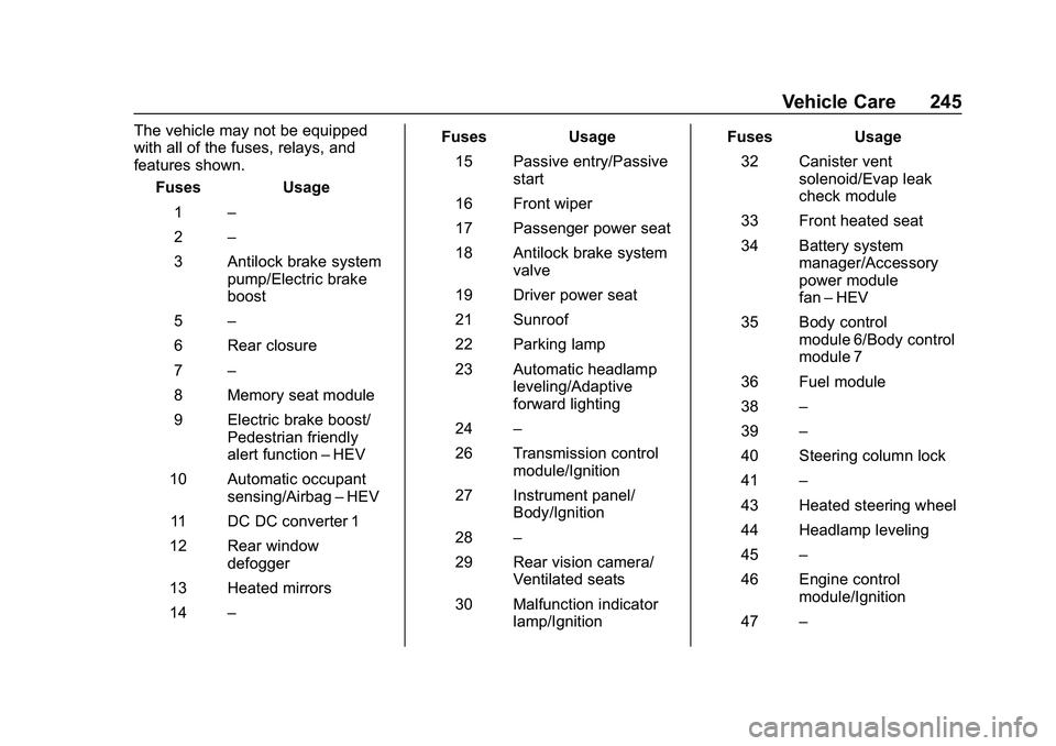
The vehicle may not be equipped
with all of the fuses, relays, and
features shown.Fuses Usage
1 –
2 –
3 Antilock brake system pump/Electric brake
boost
5 –
6 Rear closure
7 –
8 Memory seat module
9 Electric brake boost/ Pedestrian friendly
alert function –HEV
10 Automatic occupant sensing/Airbag –HEV
11 DC DC converter 1
12 Rear window defogger
13 Heated mirrors
14 – Fuses Usage
15 Passive entry/Passive start
16 Front wiper
17 Passenger power seat
18 Antilock brake system valve
19 Driver power seat
21 Sunroof
22 Parking lamp
23 Automatic headlamp leveling/Adaptive
forward lighting
24 –
26 Transmission control module/Ignition
27 Instrument panel/ Body/Ignition
28 –
29 Rear vision camera/ Ventilated seats
30 Malfunction indicator lamp/Ignition Fuses Usage
32 Canister vent solenoid/Evap leak
check module
33 Front heated seat
34 Battery system manager/Accessory
power module
fan–HEV
35 Body control module 6/Body control
module 7
36 Fuel module
38 –
39 –
40 Steering column lock
41 –
43 Heated steering wheel
44 Headlamp leveling
45 –
46 Engine control module/Ignition
47 –
Page 247 of 358
Chevrolet Malibu Owner Manual (GMNA-Localizing-U.S./Canada/Mexico-
13555849) - 2020 - CRC - 8/21/19
246 Vehicle Care
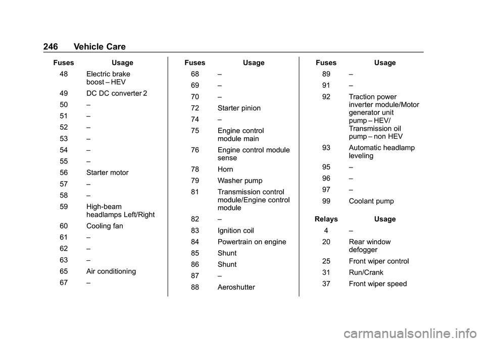
FusesUsage
48 Electric brake boost–HEV
49 DC DC converter 2
50 –
51 –
52 –
53 –
54 –
55 –
56 Starter motor
57 –
58 –
59 High-beam headlamps Left/Right
60 Cooling fan
61 –
62 –
63 –
65 Air conditioning
67 – Fuses
Usage
68 –
69 –
70 –
72 Starter pinion
74 –
75 Engine control module main
76 Engine control module sense
78 Horn
79 Washer pump
81 Transmission control module/Engine control
module
82 –
83 Ignition coil
84 Powertrain on engine
85 Shunt
86 Shunt
87 –
88 Aeroshutter Fuses
Usage
89 –
91 –
92 Traction power inverter module/Motor
generator unit
pump–HEV/
Transmission oil
pump –non HEV
93 Automatic headlamp leveling
95 –
96 –
97 –
99 Coolant pump
Relays Usage
4 –
20 Rear window defogger
25 Front wiper control
31 Run/Crank
37 Front wiper speed
Page 248 of 358
Chevrolet Malibu Owner Manual (GMNA-Localizing-U.S./Canada/Mexico-
13555849) - 2020 - CRC - 8/21/19
Vehicle Care 247
RelaysUsage
42 –
64 Starter motor
66 Powertrain
71 –
73 Air conditioning
80 Starter pinion
90 –
94 –
98 –Instrument Panel Fuse
Block
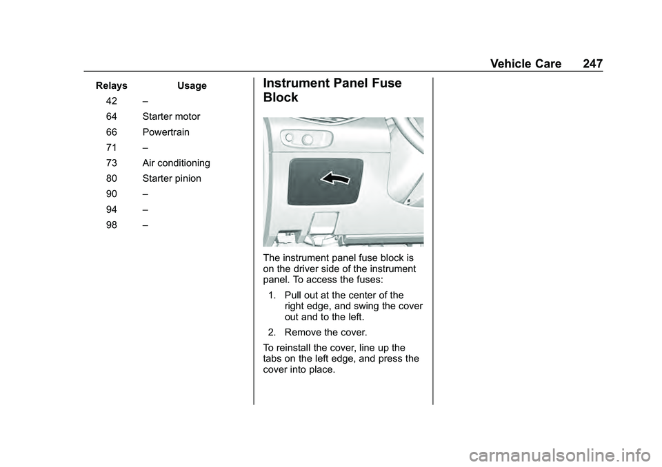
The instrument panel fuse block is
on the driver side of the instrument
panel. To access the fuses:
1. Pull out at the center of the right edge, and swing the cover
out and to the left.
2. Remove the cover.
To reinstall the cover, line up the
tabs on the left edge, and press the
cover into place.
Page 249 of 358
Chevrolet Malibu Owner Manual (GMNA-Localizing-U.S./Canada/Mexico-
13555849) - 2020 - CRC - 8/21/19
248 Vehicle Care
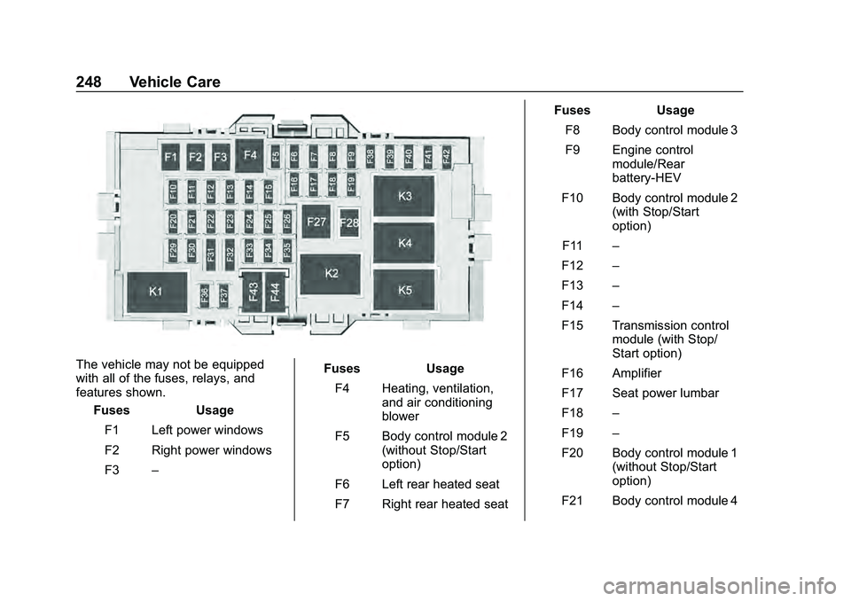
The vehicle may not be equipped
with all of the fuses, relays, and
features shown.Fuses Usage
F1 Left power windows
F2 Right power windows
F3 – Fuses Usage
F4 Heating, ventilation, and air conditioning
blower
F5 Body control module 2 (without Stop/Start
option)
F6 Left rear heated seat
F7 Right rear heated seat Fuses Usage
F8 Body control module 3
F9 Engine control module/Rear
battery-HEV
F10 Body control module 2 (with Stop/Start
option)
F11 –
F12 –
F13 –
F14 –
F15 Transmission control module (with Stop/
Start option)
F16 Amplifier
F17 Seat power lumbar
F18 –
F19 –
F20 Body control module 1 (without Stop/Start
option)
F21 Body control module 4