key CHEVROLET MONTE CARLO 1973 2.G Owners Manual
[x] Cancel search | Manufacturer: CHEVROLET, Model Year: 1973, Model line: MONTE CARLO, Model: CHEVROLET MONTE CARLO 1973 2.GPages: 86, PDF Size: 33.46 MB
Page 5 of 86
Downloaded from www.Manualslib.com manuals search engine BEFORE DRIVING YOUR MONTE CARLO
DRIVER CHECKLIST
Before Entering Car
1. See that windows , mirrors and
lights are clean.
2 . Visually note inflation condition
of tires.
3. Check that area to rear is clear
if about to back up.
Before Driving Off
1. Lock all doors.
2. Position seat and adjust head
restraints.
3. Adjust inside and outside mir
rors.
4 . Fasten seat belts.
5. Check that warning bulbs light
when key
is turned to start posi
tion.
6 . Release parking brake (and see
that brake warning light turns
off). 7
. Be sure you understand your
car and how to operate it safely.
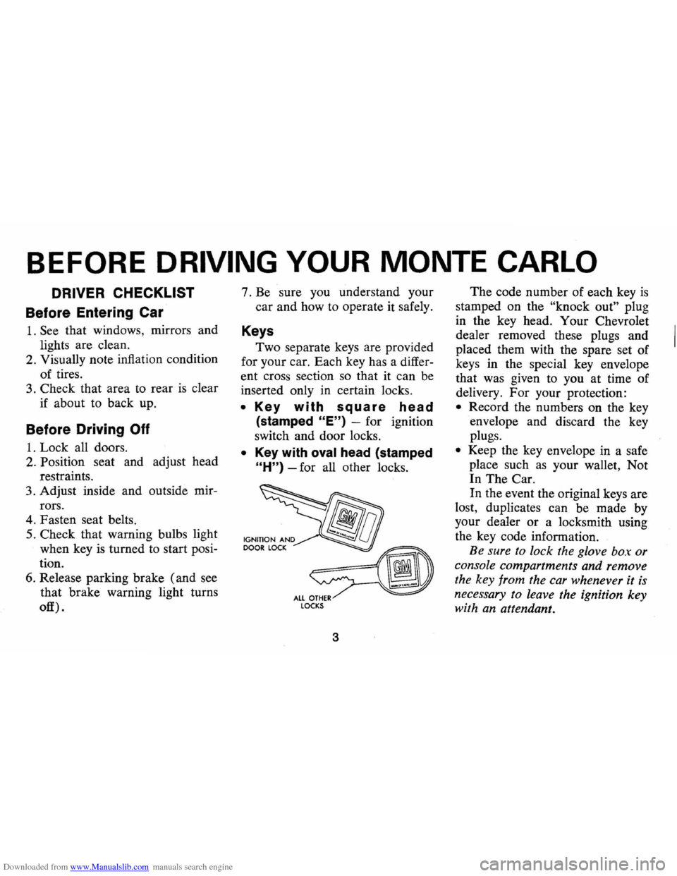
Keys
Two separate keys are provided
for your car. Each key has a differ
ent cross section so that it can be
inserted only
in certain locks.
• Key with square head
(stamped "E") -for ignition
switch and door locks.
• Key with oval head (stamped
"H") -for all other locks.
fib
~ ALL OTHER LOCKS
3
The code number of each key is
stamped on the "knock out" plug
in the key head. Your Chevrolet
dealer removed these plugs and
placed them with the spare set of
keys in the special key envelope
that was given to you at time of
delivery. For your protection:
• Record the numbers on the key
envelope and discard the key
plugs.
• Keep the key envelope in a safe
place such
as your wallet, Not
In The Car.
In the event the original keys are
lost, duplicates can be made by
your dealer or a locksmith using
the key code information.
Be sure to lock the glove box or
console compartments and remove
the key from the car whenever it
is
necessary to leave the ignition key
with an attendant.
Page 6 of 86
Downloaded from www.Manualslib.com manuals search engine Door Locks
Front side doors can be locked
from the inside by depressing the
passenger guard door lock buttons
located on the upper door panel.
All doors can be locked from the
outside by first depressing the door
lock button and closing the door.
The front doors can also be
locked by using the key.
All models have
as a standard
safety feature overriding door locks.
When the doors are locked, the
door latch mechanism
is inopera
tive, preventing inadvertent open
ing of the door by movement of the
inside handle.
REMINDER: Avoid hanging ob
jects on the right hand coat hook
in such a way that you block the
driver's vision to the right rear
quarter.
REMINDER: Always lock the
doors when driving, for greater se
curity in the event of an accident
and for security against entry by
unwelcome persons while momen
tarily stopped.
Seats
Folding seatbacks are equipped
with self-latching mechanisms and
release controls designed for the
convenience of entering and exit
ing passengers.
Manually Operated Front Seats
-The front seat can be moved
forward or rearward by moving the
control lever on the driver's side
of the seat forward and exerting
slight body pressure in the direc
tion desired. Release the lever
so
the seat will lock in the desired
position.
Back Locks-For your safety each
folding front seatback has a lock
4
which must be released before the
seatback can be folded forward.
The release lever
is located at the
lower side of each backrest nearest
the door. Move the lever upward,
then pull the seatback forward.
Keep seat belts and
bu.c~les
clear of mechanism when tlltmg
folding seats forward or backwards,
to prevent damage to these belt
restraints.
Bucket Seats
The front seats may be adjusted
to suit an individual's preference.
Simply release the seat lock mech
anism located at the front of the
seat.
Once released, exert slight
body pressure in the direction de
sired. Release the lever so the seat
will lock in the desired position.
Swivel Bucket Seats
The swivel bucket seat can be
turned towards the door opening
Page 7 of 86
Downloaded from www.Manualslib.com manuals search engine to provide front seating conve
nience and easy entrance into the
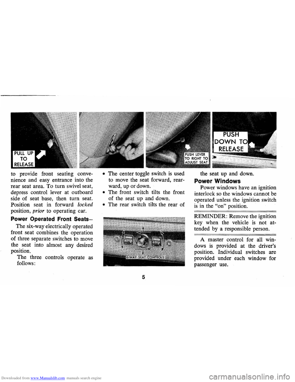
rear seat area. To turn swivel seat,
depress control lever at outboard
side of seat base, then turn seat.
Position seat in forward
locked
position, prior to operating car.
Power Operated Front Seats-
The six-way electrically operated
front seat combines the operation
of three separate switches to move
the seat into almost any desired
position.
The three controls operate
as
follows:
• The center toggle switch is used
to move the seat forward, rear
ward, up or down.
• The front switch tilts the front
of the seat up and down.
• The rear switch tilts the rear of
5
the seat up and down.
Power Windows
Power windows have an ignition
interlock so the windows cannot be
operated unless the ignition switch
is in the "on" position.
REMINDER: Remove the ignition
key when the vehicle
is not at
tended
bya responsible person.
A master control for all win
dows
is provided at the driver's
position. Individual switches are
provided under each window for
passenger use.
Page 11 of 86
Downloaded from www.Manualslib.com manuals search engine • To fasten the shoulder belt, un
stow it and place the knob on
the shoulder belt end in the
keyhole on the lap belt latch
plate. (The latch
is designed so
that this attachment can only be
completed before fastening the
lap belt.) Tilt the knob as neces
sary, to pass
it through the slot.
Pull the knob firmly upward to
seat it at the narrow end of the
keyhole, then fasten the lap belt.
• Shoulder belts are lengthened
and shortened in the same man
ner
as center seat lap belts.
• Shoulder belt should have suf
ficient slack to insert a fist's
width between your chest and
the belt. This can be checked
by inserting a clenched
fist be
tween the belt and your chest
with thumb against chest and
back of hand facing upward.
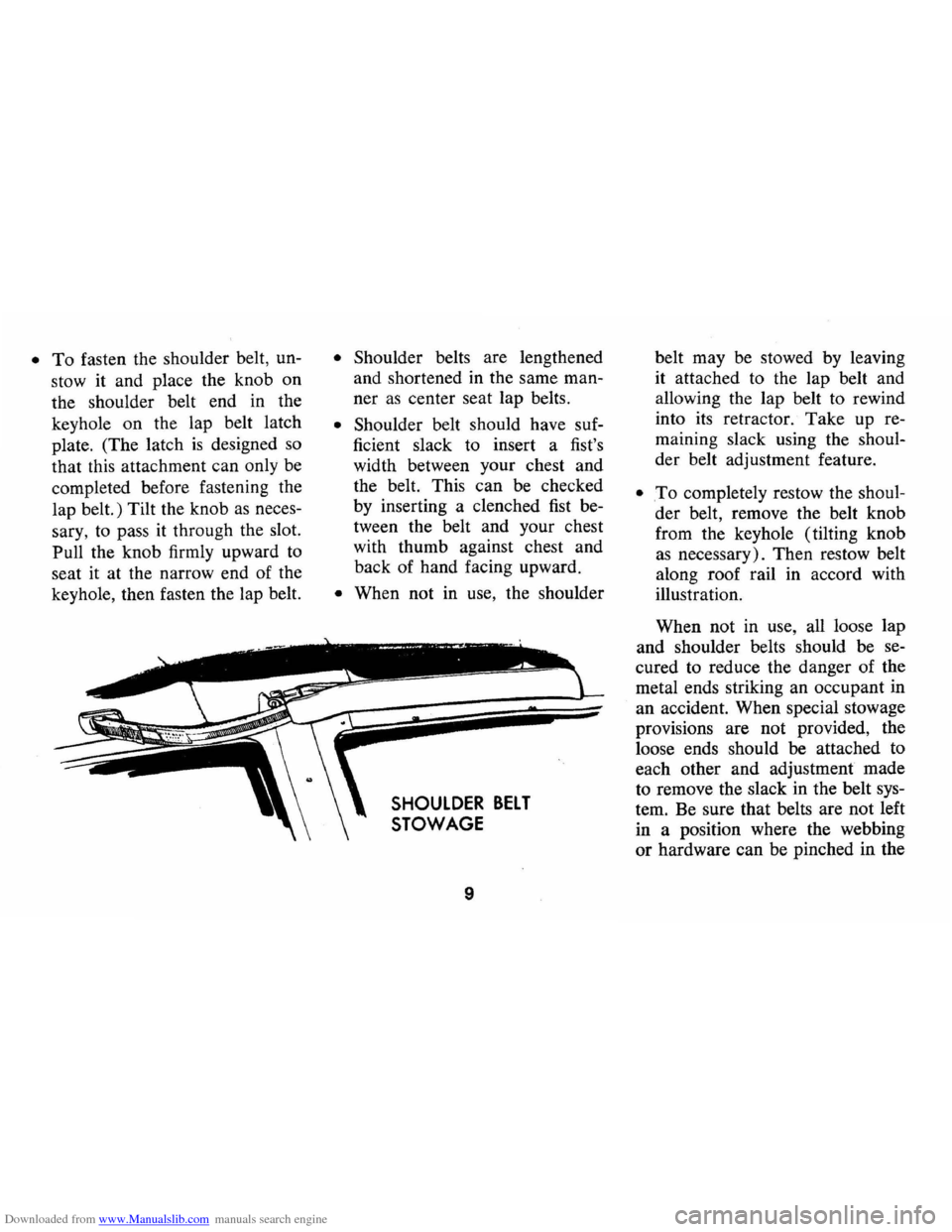
• When not in use, the shoulder
SHOULDER BELT
STOWAGE
9
belt may be stowed by leaving
it attached to the lap belt and
allowing the lap belt to rewind
into its retractor.
Take up re
maining slack using the shoul
der belt adjustment feature.
• .To completely restow the shoul
der belt, remove the belt knob
from the keyhole (tilting knob
as necessary). Then restow belt
along roof rail in accord with
illustration.
When not in use, all loose lap
and shoulder belts should be se
cured to reduce the danger of the
metal ends striking an occupant in
an accident. When special stowage
provisions are not provided, the
loose ends should be attached to
each other and adjustment made
to remove the slack in the belt sys
tem. Be sure that belts are not left
in a position where the webbing
or hardware can be pinched in the
Page 17 of 86
Downloaded from www.Manualslib.com manuals search engine STEERING COLUMN CONTROLS
Anti-Theft Steering
Column Lock
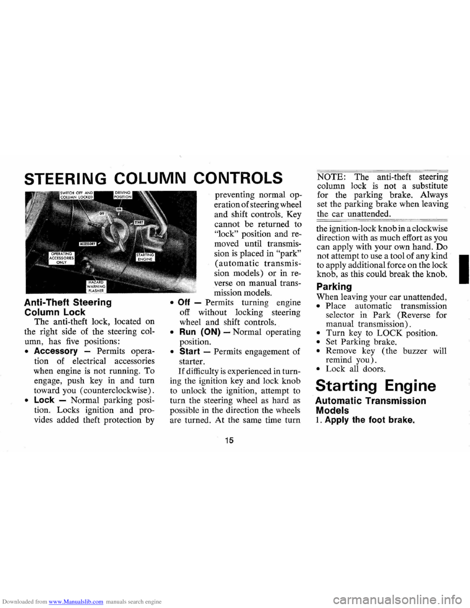
The anti-theft lock, located on
the right side of the steering col
umn, has
five positions:
• Accessory -Permits opera
tion of electrical accessories
when engine
is not running. To
engage, push key in and turn
toward you (counterclockwise).
• Lock -Normal parking posi
tion. Locks ignition and pro
vides added theft protection by preventing
normal op
eration of steering wheel
and shift controls. Key
cannot be returned to
"lock" position and re
moved until transmis
sion
is placed in "park"
(automatic transmis
sion models) or in re
verse
on manual trans
mission models.
• Off - Permits turning engine
off without locking steering
wheel and shift controls.
• Run (ON) -Normal operating
position.
• Start -Permits engagement of
starter.
If difficulty is experienced in turn
ing the ignition key and lock knob
to unlock the ignition, attempt to
turn the steering wheel
as hard as
possible in the direction the wheels
are turned.
At the same time turn
15
NOTE: The anti-theft steering
column lock
is not a substitute
for the parking brake. Always
set the parking brake when leaving
the car unattended.
the ignition-lock knob in a clockwise
direction with
as much effort as you
can apply with your own hand.
Do
not attempt to use a tool of any kind I
to apply additional force on the lock
knob,
as this could break the knob.
Parking
When leaving your car unattended,
• Place automatic transmission
selector in
Park (Reverse for
manual transmission).
• Turn key to LOCK position.
• Set Parking brake.
• Remove key ( the buzzer will
remind
you).
• Lock all doors.
Starting Engine
Automatic Transmission
Models
1. Apply the foot brake.
Page 18 of 86
Downloaded from www.Manualslib.com manuals search engine 2. Place transmission selector
in uP" or uN" (UP" preferred).
A starter safety switch prevents
starter operation while the trans
mission selector
is in any drive
position.
(If it is necessary to
re-start the engine with the car
moving, place the selector lever
in
"N".)
3. Depress accelerator pedal and
activate starter
as outlined be
low for different conditions.
• Cold Engine -Fully de
press
accelerator pedal and
slowly release.
With foot off
the pedal, crank the engine
by turning the ignition key
to the Start position-release
when engine starts.
If engine starts, but fails to
run, repeat this procedure.
When engine is running
smoothly (approximately 30
seconds), the idle speed may
be reduced by slightly de- pressing
the accelerator pedal
and then slowly releasing.
• Warm Engine -Depress ac
celerator
pedal about halfway
and hold while cranking the
engine.
• Extremely Cold Weather
(Below 0° F.) Or After Car
Has Been Standing
Idle
Several
Oays-
Fully depress and release
accelerator pedal two or three
times before cranking the
engine.
With foot off the ac
celerator pedal,
crank the
engine by turning the key to
the Start position and release
when engine starts.
Manual Transmission Models
1. Apply parking brake and shift
16
transmission to neutral.
2.
Hold clutch pedal to floor
throughout the starting proce
dure.
A starter interlock pre
vents starter operation when
clutch
is not fully depressed.
(Select the proper gear position
before releasing the clutch pedal.)
3. Operate accelerator pedal and
starter
as outlined in step 3
(under Automatic Transmission
Models).
Engine Flooded
Depress accelerator pedal aJ;ld
hold to floor while starting until
engine
is cleared of excess fuel
and
is running smoothly. Never
"pump" the accelerator pedal.
Warm-Up
Always let the engine idle for
20 to 30 seconds after starting
and drive at moderate speeds for
several miles, especially during
cold weather.
Page 21 of 86
Downloaded from www.Manualslib.com manuals search engine Driving with Manual Transmissions
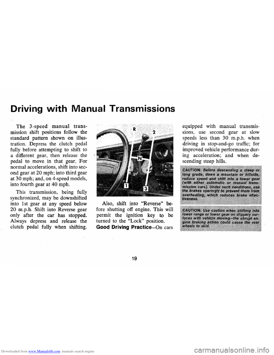
The 3-speed manual trans
mission shift positions follow the
standard pattern shown on illus
tration. Depress the clutch pedal
fully before attempting to shift
to
a different gear, then release the
pedal to move in that gear.
For
normal accelerations, shift into sec
ond gear at
20 mph; into third gear
at
30 mph; and, on 4-speed models,
into fourth gear at
40 mph.
This transmission, being fully
synchronized, may be downshifted
into 1 st gear
at any speed below
20 m.p.h. Shift into Reverse gear
only after the car has stopped.
Always depress and release the
clutch pedal fully when shifting. Also,
shift into
"Reverse" be
fore shutting
off engine. This will
permit the ignition key to be
turned to the
"Lock" position.
Good Driving Practice-On cars
19
equipped with manual transmis
sions, use second gear at slow
speed s less than
30 m.p .h. when
driving in stop-and-go traffic; for
improved vehicle performance dur
ing acceleration; and when de
s cending steep hills.
Page 29 of 86
Downloaded from www.Manualslib.com manuals search engine Generator Indicator Light
This light provides a quick
check on the generating system
of your car. The red light will
go on when the ignition key
is
in the "on" position, but before
the engine
is started. After the
engine starts, the light should go
out and remain out.
If the light
remains on when engine
is run
ning , have your Authorized Chev
rolet Dealer locate and correct
the trouble
as soon as possible.
Engine Temperature
Indicator Light
This indicator light is provided
in the
instrument cluster to
quickly warn of an overheated
engine. With the ignition switch
in the
START position, the red
TEMP indicator will light to let
you know that it
is operating
properly. When the engine
is started, the red
light will go out immediately.
It will light up at no other time
unless for some reason the engine
reaches a dangerously high oper
ating temperature.
If the red light
should come on, the engine must
be stopped until the cause of the
overheating
is corrected. Glance
at instrument cluster frequently
as
you drive to see if this light is on.
Brake System Warning Light
The service brake system is
designed so that half of the brake
system will provide some braking
action in the event of a hydraulic
leak in the other half of the
sys
tem. If the warning light located
below the fuel gauge glows con
tinuously when the ignition
is on
and after the brakes have been
firmly applied, it may indicate that
there
is a malfunction in one half
of the brake hydraulic system.
27
• As a check on bulb condition
the light should glow with the
parking brake applied and the
ignition on. (Light
is also a
reminder to release parking
brake) .
• Have system repaired if light
does not come on during check.
• This warning light is not a sub
stitute for the visual check of
brake fluid level required
as
part of normal maintenance.
If the light glows red:
• The parking brake control is not
fully released or,
• The service brake system is
partially inoperative
What to do:
1. Check that the parking brake
is released. If it is ...
2. Pull off the road and stop,
carefully- remembering that:
Page 31 of 86
Downloaded from www.Manualslib.com manuals search engine _ '\' ' 2
1
5 , / '/ ,
[ e /~
O'v RPM !lOa -"-50
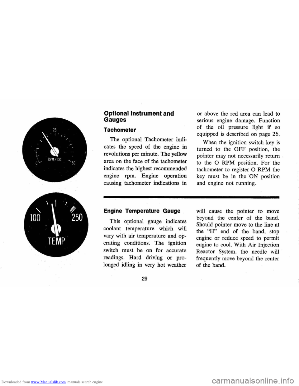
Optional Instrument and
Gauges
Tachometer
The optional Tachometer indi
cates the speed of the engine in
revolutions per minute. The yellow
area on the face of the tachometer
indicates the highest recommended
engine rpm. Engine operation
causing tachometer indications in
Engine Temperature Gauge
This optional gauge indicates
coolant temperature which will
vary with air temperature and op
erating conditions. The ignition
switch must be on for accurate
readings. Hard driving
or pro
longed idling in very hot weather
29
or above the red area can lead to
serious engine damage. Function
of the oil pressure light if
so
equipped is described on page 26.
When the ignition switch key
is
turned to the OFF position, the
pointer may not necessarily return
'
to the 0 RPM position. For the
tachometer
to register 0 RPM the
key must be in the
ON position
and engine not running.
will cause the pointer to move
beyond the center of the band.
Should pointer move to the line at
the
"H" end of the band, stop
engine
or reduce speed to permit
engine to cool. With Air Injection
Reactor System, the needle will
frequently move beyond the center
of the band.
Page 72 of 86
Downloaded from www.Manualslib.com manuals search engine as a screwdriver handle or pliers. Replace the oir cleaner and attempt to start the engine in the normal manner. (E) If the car will start but stalls when hot or has a rough idle, you can suspect a faulty IDLE ADJUSTMENT, a malfunctioning AUTOMATIC CHOKE or an extremely dirty and blocked AIR CLEANER ELEMENT. Replace paper element air cleaner if necessary. Idle adjustment or automatic choke service (other than that outlined in paragraph 0 above) should be performed by your Chevrolet
Dealer. If the above Fuel System checks and the checks suggested under
the Electrical System following do not correct the malfunction, it is recommended that you turn to your Authorized Chevrolet Dealer
for further checks, adjustments or repairs. ELECTRICAL SYSTEM If when the ignition key is turned to "Start", the engine will not turn' over, yOu have good reason to suspect electrical trouble. NOTE: Never'remove Delcotron bat lead without first disconnecting battery ground cable. IF) When there is no response at all to attempts to start the car,
check the obvious-your AUTOMATIC TRANSMISSION SELECTOR LEVER must be in Neutral or Park position (manual transmission
must have clutch depressed all the way to floor) before the engine
can be starfed. Turning the IGNITION SWITCH rapidly back and forth several times will sometimes correct a poor internal switch
contact.
(GI The BATTERY may be discharged. If so, lights will be dim and the horn will have a poor tone if it will blow at all.
Usually a garage recharge will be necessary to return the battery to operation. Occasionally, however, a long drive will recharge the battery. . , •
NOTE: If the baHery is determined to be dead, and for no apparent reason, have your :Aflthori~ed Chevrolet Dealer check the baHery, the GENERATOR and the VOLTAGE REGULATOR.
GENERATOR trouble shqiJld already have been indicated by
69
the generator indicator light on the instrument panel.
POOR BATTERY CONNECTIONS may be suspected if the car has operated properly a short time before and now not even the horn will operate. Check both ends of both battery cables. If the connections are corroded, a car may sometimes be restored to operation by removing all cable ends, scraping all contacting surfaces
clean with a pen knife, and reassembling. If the cables are broken,
they must be replaced. The power supply should now be restored unless-the battery is dead.
(HI If, however, the lights and horn work properly but the starter will still not turn over, check the STARTER connections. A "click" from the starter solenoid indicates that the wiring to the starter is properly installed. If the wiring seems to be clean and tightly installed, the trouble is probably in the starter itself and should be referred to your Authorized Chevrolet Dealer.
When the engine will "turn over" but will not start, the following
items may be checked along with the Fuel Systems Checks listed previously.
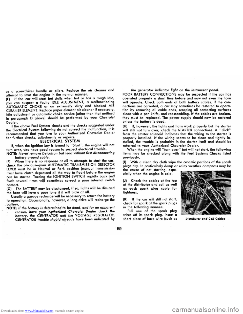
(II With a clean dry cloth wipe the ce-amic portions of the spark plugs dry. In particularly damp or rainy weather dampness may be the cause of not starting, espe
cially when the engine is cold.
(JI Check the cables at the top
of the distributor and coil as well as each spark plug cable for
tightness.
(KI If the car will still not start,
check for spark at the spark plugs in the following manner: Pull one of the spark plug
wires off its spark plug. Insert a
short piece of bare wire (such as Distributor and Coli Cables