check engine light CHEVROLET MONTE CARLO 1976 2.G Owners Manual
[x] Cancel search | Manufacturer: CHEVROLET, Model Year: 1976, Model line: MONTE CARLO, Model: CHEVROLET MONTE CARLO 1976 2.GPages: 102, PDF Size: 23.79 MB
Page 3 of 102
Downloaded from www.Manualslib.com manuals search engine ,
BEFORE DRIVING YOUR CHEVROLET
DRIVER CHECKLIST
Before Entering Car
1. See that windows ; mirrors and
lights are clean.
2. Visually note inJIation condition
of tires.
3. Check that area to rear is clear
if about to back up.
Before Driving Off
1. Lock all doors.
2. Position seat, jmd adjust head
restraints, if
so ¢quipped.
3. Adjus!insidean'd outside mirrors.
4. Fasten seat belts.
5. Check that warning bulbs light
when key
is turned to start
position. .
6. Release parking brake ( and see
that brake warning light turns
off). ,
7. Be sure you understand your car
and how
to 'operate it safely.
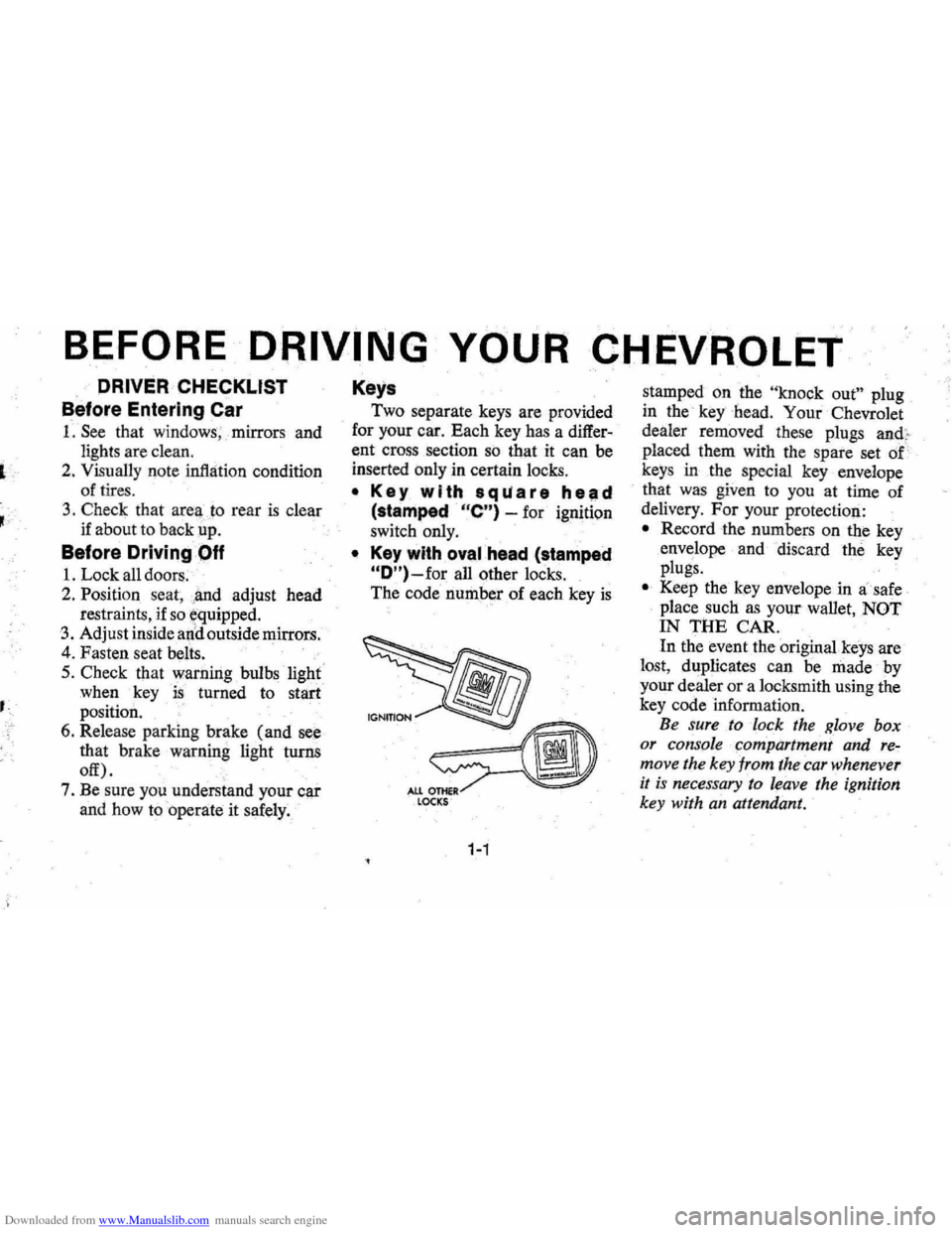
Keys
Two separate keys are provided
for your car. Each key has a
differ
ent cross section so that it can be
inserted only in certain locks.
• Key with s qua r e hell d
(stamped "e") -for ignition
switch only.
• Key with oval head (stamped
"O")-for all other locks.
,
The code number of each key is
All OTHeR LOCKS
1-1
stamped on the "knock out" plug
in the '
key-bead. Your Chevrolet
dealer removed these plugs
and,.
placed them with the spare set of
keys in the special key envelope
. that was given to you at time of
delivery.
For your protection:
• Record the numbers on the key
envdope and discard the key
plugs.
• Keep the key envelope in a safe
place such
as YOII! wallet, NOT
IN THE CAR.
In the event
the original keys are
lost,
dl!plicates can be made by
your dealer or a locksmith using the
key code information.
Be sure to lock the Klove box
or console
90mpartment and re~
move the key from the car whenever
it is necessary to leave the ignition
key with
an attendant.
Page 20 of 102
Downloaded from www.Manualslib.com manuals search engine such as changing lanes on an ex
pressway , the steering wheel
is not
turned back sufficiently after com
pleting the turn to automatically
cancel the turn signal.
For con
venience
,in such maneuvers, the
driver can flash the turn signals by
moving the turn signal lever part
way (to tlie first stop) and holding
it there. The lever returns to the
neutral
or canceled position when
the driver releases his hold on the
lever. A
green light on the instrument
cluster flashes to indicate proper
operation of the front and rear turn
signal lamps.
If the indicator lamp
. remains on and does not flash,
check for a defective lamp bulb.
If
the indicator fails to light when
the lever
is moved , check the fuse
and indicator bulb.
Power Steering
If the steering system power as
sist fails due to some malfunction, or
because the. engine has stalled,
the car can still be steered. How
ever; much greater effort is re
quired particularly in sharp turns.
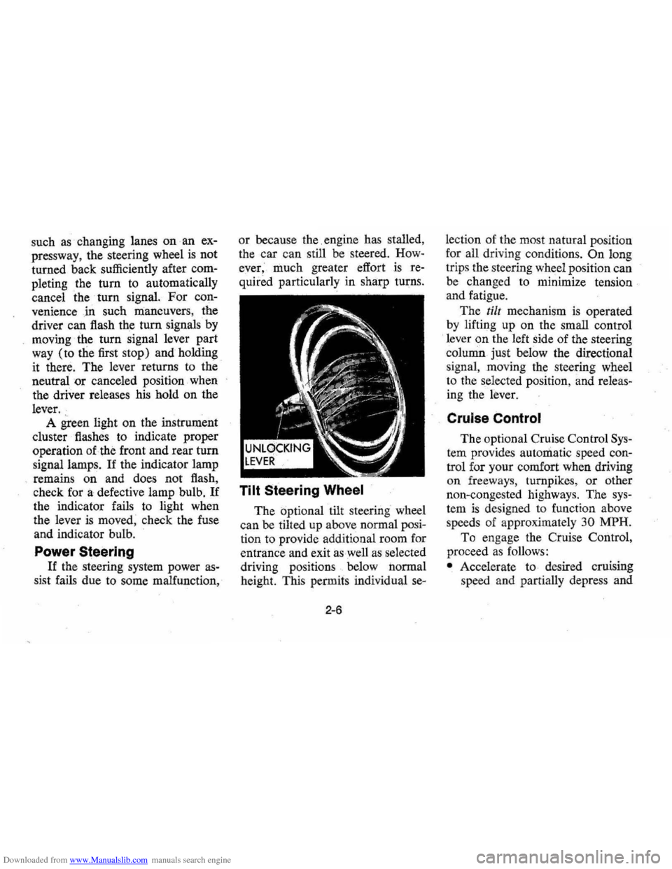
Tilt Steering Wheel
The optional tilt steering wheel
can be tilted up above normal posi
tion to provide additional room for
entrance and exit
as well as selected
driving positions below normal
height. This permits individual
se-
2-6
lection of the most natural position
for all driving conditions.
On long
trips the steering wheel position can
be changed to minimize tension
and fatigue.
The
till mechanism is operated
by lifting up on the small control
lever
on the left side of the steering
column just below the directional
s ignal , moving the steering wheel
to the selected position, and releas
ing the lever.
Cruise Control
The optional Cruise Control Sys
tem provides automatic speed con
trol for your comfort when driving
on freew a
ys, turnpikes, or other
non-congested highways. The
sys
tem is designed to function above
speeds of approximately
30 MPH.
To enga ge the Cr:uise Control,
proceed
as follows:
• Accelerate to desired cruising
speed and partially depress and
Page 23 of 102
Downloaded from www.Manualslib.com manuals search engine NOTE: "Riding the brake" by rest
ing your foot on the brake pedal
when not intending to brake can
cause abnormally
high brake tem
peratures, excessive lining wear and
possible damage to the brakes,
in
addition to wasting.gasoline.
Self-AdjustingiBrakes
• Brakes on th(i; ' car (except for ••.
the parking }prake) are self
adjusting, designed to eliminate
periodic
brake adjustments.
• Drum brake adjustment is made
automatically
as the brakes are
applied while car is moving
backwards.
• Disc brake . adjustment is made
automatical1y with each brake
application.
• If excess brakep~dal travel de
velops, drive alternately back-
ward and forward (several
times) and apply brakes firmly
in each direction.
• See )lour dealer if normal pedal
travel is not restored, or if there
is a rapid increase in pedal travel,
which could be a sign of other
brake trouble.
See y6ur dealer also if
adjust
ment of the parking brake is
required;
REMINDER: The front disc
brakes have a built-in wear indica
tor that is designed to make a high
frequency squealing,
or cricket-like
warning sound when the linings are
worn to where replacement
is re
quired. The sound will occur inter
mittently or continuously when
wheels are rolling, but will
dis
appear when the brake pedal is ap-
2-9
plied firmly. See also the various
brake checks listed in the
Chevro
let maintenance schedule folder.
Headlight Beam Switch
"High" and "low" headlight
beams are controlled by the floor
button at your left foot. The
indi
cator, located next to the speed
ometer dial, will light up when the
high beams are in use.
Page 26 of 102
Downloaded from www.Manualslib.com manuals search engine ble'can be located and corrected .
. Driying the car with low oil pillS'
sure can:cause · serious ' engine
damage.
Genera~orlndicator Light
The red light will go on when
the
ignition key is in the "on " posi,
tion, b~f before the engine is
started.'J\fter the engine starts, the
light .
sho'uld go out and remain out.
If the Hght remains on when engine
is runlling, have your Authorized
Chevrolet Dealer locate and cor,
reCI the trouble as soon as possible,
Engine Temperature
Indicator Light
, This indicator light is provided
in the instrument cluster to quickly
warn
of an overheated engine. With
the ignition switch in the
5T AR T
position, the red TEMP indicator
will light to let you know that it is
operating properly. When
the engine
is started , the
red light will go out immediately,
It will light up at no other time
unless for some reason the engine
.
reaches a dangerously high oper,
atingtemperature. If the light
comes on during
extreme driving
conditions, such
as an extended
idle, turn
off the air conditioner (if
used }.and run the engine slightly
faster than
idle. speed with the
transmission in neutral gear .
If the
light does not go
off within a short
period of time
(F2 minutes), then
tum the engine off until the cause
of the.
overheating is corrected;
Glance at the
Ins.trument cluster
frequently as you drive to see if
this light
is on. '
Brake System Warning
Light
.
The service .. brake system is a
dual system designed
so that. one
part will provide some braking
2-12
action in the event of loss of hy'
draulic pressure in the other part of
the system.
If the ,warning light
labeled
"BRAKE," located in the
speedometer face, comes on .and
stays on when the ignition
is on and
'after · the brakes have been firmly
applied, it may indicate that
there
is a malfunction in one part of the
brake system.
'
•
As ~ reminde;, the light is de,
signed:to
come on with the park,
ing brake applied and the ignition
on.
• The light is also designed to
come on, during ;engine starting
to verify that the bulb is operating
. properly.
• Have system repaired '. if light
does not come
on' during check.
• This warning light, is not a sub
stitute for the visual check of
brake fluid level required
as part
of normal maintenance.
Page 27 of 102
Downloaded from www.Manualslib.com manuals search engine If the light comes oQ:
• The :parking brake control is not
fully
relea sed or, ,,:
• The service brake system is
partially inoperative .
What to do :
1. Check that the parking brake
is released. If it is ...
2.
Pull off the road and stop, care
fully-remembering that:
'
•
Stoppin g "distances may be
greater. ' '0:
• Greater pMal effort may be
required .: ;
• Pedal
travel may be greater.
3. Try out b~ake operati on by start
ing and
stopping on road shoul
der-then :
• If you judge such operation to
be safe , proceed cautiously at
a safe speed to neare st dealer
for repair.
• Or have car towed to dealer
}or repair .
Continued operation ' of the car in '
this condition
is dangerous.
Headlight High Beam
Indicator Light
The headlights of your ' car have '
high and
low, beams to provi(je you
with proper night-time visibility
for most . driving
conditioQs. The
"low" beams are used during most
city driving. The
"high" beams are
especially useful when
drh;ing on
dark roads since
they provide ex
cellent long range illumination.
The headlight beam
indicator will
be on whenever the high beams or
"brights" are in use. The Headlight
Beam
Switch controls the headlight
beams (see
Page 2-9).
Light Switch
The three position light switch
controls the headlights " taillights,
parking lights, side marker lights,
2-13
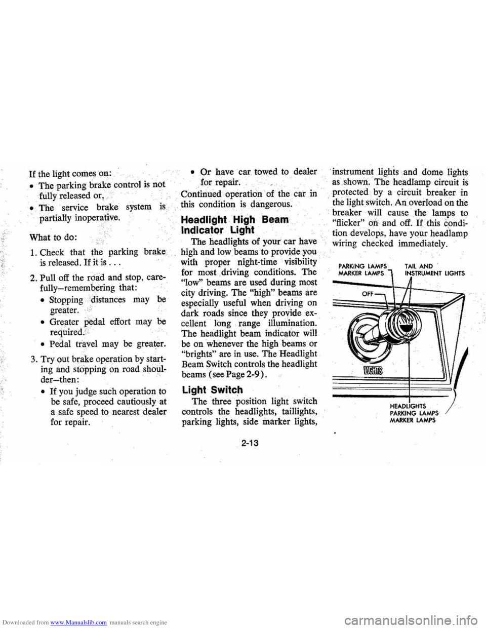
'i nstrument lighis and dome lights
a s ,shown . The headlamp circuit
is
protected·· by a circuit breaker in
, tne lightswit ch . An overload on the
breaker will cause the lamps to
"flicker" 00 and off. If this condi
ti on develop s, hav e your headlamp
wiring check ed immedi ately.
PARKING MARKER LAMPS TAIL AND
PARKING LAMPS MARKER LAMPS
LIGHTS
Page 49 of 102
Downloaded from www.Manualslib.com manuals search engine Your Chevrolet may be towed
on all four wheels , at speeds of less
than
35 mph, for distances up to
50 miles, provided the driveline,
axle , tranSmission, and steering
sys
tem are otherwise normally oper
able.
Use only towing equipment
specifically designed for this
pur'
pose following the instructions of
the
towing equipment manufac
turer.A separllte safety chain sys
tem must be used. For such towing
the steeringi;Dust be unlocked,
' transmission in neutral
an~ the
parking brake released. Attach
ments must
oe made to mai!1 ,struc
tural members of the car. Do not
attach to bumpers or
,aSsociated
brackets. ' Remember that power
brake and power steering assists
will not be ,available when engine
is inoperative,
EMERGENCY STARTING
NOTE: Do not push or low this
vehicle to start. Damage to the cata
lytic converter and / or to other parts
of the vehicle may result.
• A car with a discharged 'battery
may be started by using energy
from a battery
in' another car
call<:!d "jump starting ".
Jump Starting
Jump starting may be dangerous
and should
be attempted only if the
followi!1g three , ,~onditions are met.
If they are not, we strongly,~ecom
mend that you leave the starting to
a competent mechanic.
• The battery in the OTHER vehi
cle must be
12 volt and negatively
3-2
grounded, like the, one in TillS
car. (Check the' other car's
owner's manual
to see if it is.)
• The battery in THIS car must be
equipped with
flame arrestor
type
filler / venl caps on all filler
openings (as
was the original
equipment
De ,lco battery), or it
, must be a sealed-type battery
which does not have
fi'tler open
ings or
caps, (Each Delco bat
tery flame arrestor cap has a grey
disc rather than a small hole-see
illustration. )
•. If thebatiery is a Delco sealed
type battery without filler open
ings or
caps"its charge indicator
must be dark, with or without
green dot showing, see illustra
tion. Do
NOT attempt jump start
ing
if the charge indicator has a
light or bright center.
Page 53 of 102
Downloaded from www.Manualslib.com manuals search engine 7. Raise vehicle so tire just clears
surface, replace wheel and
slight
ly tighteawheel nuts.
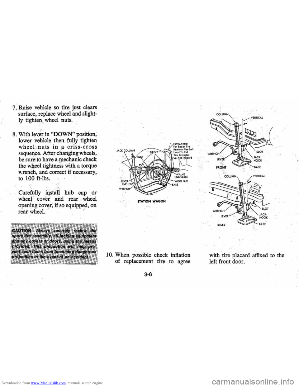
8. With leyer in "DOWN" position,
lower vehicle then fully tighten
wheeLnuts in a criss-cross
seq ueIice. After chariging wheels,
be sure,to have a mechanic check
the wheel tightness with a torque
"rench, and correct if necessary ,
to 100 ft-lbs.
Carefully instali hub cap or
wheel '
covet and rear.' wheel
opening cover, if
so equipped, on
rear wheel.
.
STATION WAGON
10. When possible check inflation
of replacement tire
to a,gree
3-6
with tire placard affixed to the
left front door.
Page 73 of 102
Downloaded from www.Manualslib.com manuals search engine Accelerator Linkage
Lubricate with engine oil every
15,000 .miles as follows:
1. V-8 Engine-lubricate cable pin
at the carburetor lever.
Hinges
The following points should be
checked and lubricated every 6
months or
7,500 miles, whichever
occurs first: hinges on all doors,
fuel filler door, trunk lid, door lock
striker and door jamb switches.
Hood Latches
Every 6 months or 7,500 miles
whichever occurs first, lubricate
hood latch assembly and hood
hinge assembly
as follows:
1. Wipe off any accumulation of
dirt or contamination on latch
parts.
2. Apply Lubriplate
or equivalent
to latch pilot bolts and latch
locking
plate,
3. Apply light engine oil to all
pivot points in release
mecha
nism, as well as primary and
secondary latch mechanisms.
4. Lubricate hood hinges.
5. Make hood hinge and latch
mechanism functional check to
5-12
asSUre the assembly is working
correctly.
Air Conditioning
Have your Chevrolet Dealer
check your Air Conditioning
sys
tem at some time during the winter
months to be sure there has been
no loss in cooling output. During
the summer, see your Chevrolet
Dealer immediately if you suspect
the system
is nof performing as it
should.
NOTE: Your car's air condition
ing system will not operate be
low ambient temperatures of 300P
( -1°C) regardless of control
position.
Page 87 of 102
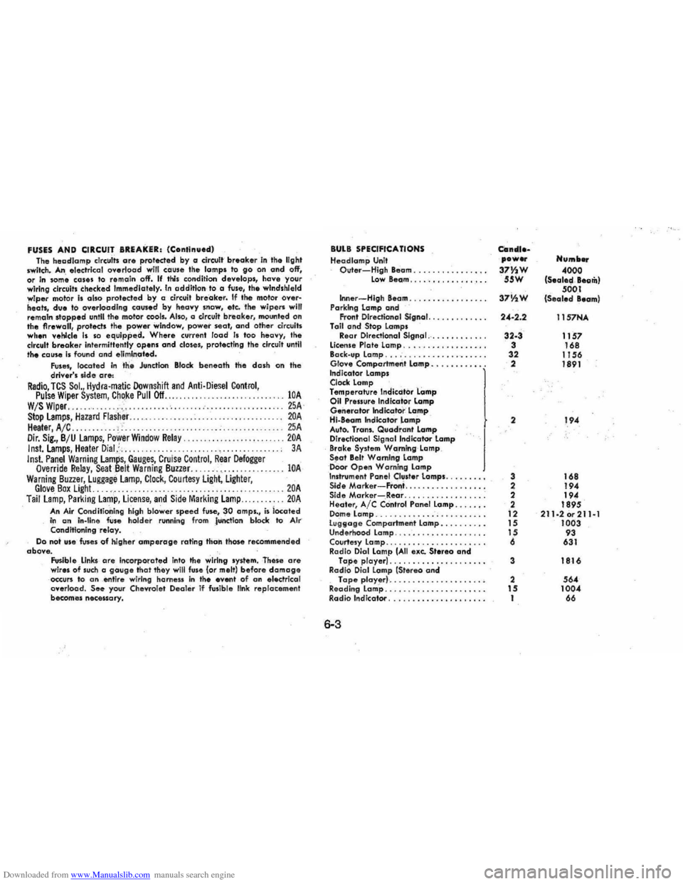
Downloaded from www.Manualslib.com manuals search engine FUSES AND CIRCUIT BREAKER: (Continued) Tho hSDdlomp clrculls are proleded by a dreult breaker In the light Iwitch. An slsc:trlcol overload will cause the lamps to go on and off, or In som~ cOles to remain off'. If this condition deve lo ps, have your
wiring circuit. checked Immediately. In addition to a fuse, the windshield
wiper mot or Is also protected by a circuit breaker. If the motor oyer· heats, due to overk>adlng caused by heClvy snow, etc. tl\e wipers will
remam stopped unltl the motor cools. Also, a c.Irc:uit brea ker. mounted on
the firewall, protects the power window, power seat, and other circuits when vehicle Is so equipp.d. Where current load Is too heavy, the
circuit breake r Intermittently opens and closes, protecting the circuit until the cause Is found and eliminated. Fuses, located in the Junction Block beneath the dash on the driver's .Ide are: Radio, TCS SoL, Hydra·matic Downshift and Anti·Diesel Control, Pulse Wiper System, ChQke Pull Off ........................ . W/S Wiper............. .• . .. . .................... . Stop Lamps, Hazard flasher..... . ......... . Heater, A /C ...... . . .. ' Dir. Sig., B /U lamps, Power Window Relay. Inst.lamps, Heater Dial,::, ..... Inst. Panel Warning Lamps, Gauges, Cruise Control, Rear Defogger Override Relay, SeaL8elt Warning Buzzer. ..... -. c •••••. Warning Buuer, Luggage Lamp, Clock, Courtesy Light, Ligflter,
lOA 25A lOA 25A .. 20A 3 A
lOA
Glove Box Light. . . . .. . . . . . . . ..... 20A Tail lamp, Parking Lamp, License, and Side Marking Lamp... . ..... 20A
An Air Conditioning high blower speed fuse, 30 amps., is located in an In-tine fuse holder runnin g from JUnction block to AI ... Conditioning -relay. Do not Ufe fuses of higher amperage rating than those recommended
obove. Fusible ,
LInks are in(:orporated into 'he wiring system. These are wires of such a gauge that they will fuse (or melt) before damage occun to an _ent ire wiring harn ess in tile even' of an electrical
overload. See your Chevrole t Deal er if fusible link re placement
becom es necessary.
BULB SPECIFICATIONS Heodlamp Unit Outer-High Beam ..........•..•.. Low 8eam .... · .•.••..••....
Inner -High Beam .......... , . •.. .. Parking lamp and Front Directional Signal. .......••... Toil and Stop Lamps Re,ar Directianal Slgn(ll .......•..... license Plate Lamp ............•..... Back.up Lamp ................•.••.. Glo .... Comportment lamp .•..••.....• Indicotor lamps Clock lamp Temperature Indicdtor Lamp 011 Pressure Indica'tor lamp Generator Indicator lamp Hi-880m Indkator lamp Auto. Trans. Quadrant Lamp
Directional Signal Indicator Lamp
Brake System W,a ,rn!ng Lamp Seat Belt Warning Lamp oOor Open Warning Lamp Inshvmen' Panel Ou.ter lamps. Sid. Morker-FrOl1i ................. . Side Marker-Rear ................. . Heater, Ale COntrol Panel Lamp .....•.
D ome Lamp ....................... . lU9t1oge Compartment Lamp ......... . Underhood lamp ................... . Courtesy Lamp ..................... .
Radio Dial Lamp (All exe. Stereo ond Tape player) . . ................ . RadiO, Oial Lamp (Stereo and Tape player) .................... .
Reading lamp ..................•... Radio Indicator .......••..••.•.••...
6-3
Can_uea power Humb ...
37Y~W 4000 55W (S.ale~, Beom)
37V1W 5001 (Sealed Beam)
24-2.2 11S7NA
32-3 1157 3 168
32 I J 56 2 1891
2 194
3 168
2 194
2
194
2 1895
12 211·2or211al 15 1003 15 93
6 631
3 1816
2 564 15 1004 I 66
Page 92 of 102
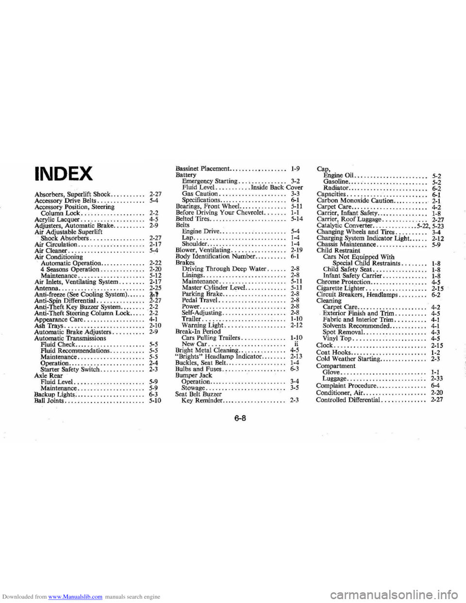
Downloaded from www.Manualslib.com manuals search engine INDEX
Absorbers, Superlift Shock. . . . . . . . . .. 2-27
Accessory Drive Belts. . . . . . . . . . . . . .. 5-4 Accessory P()sition, Steering Column Lock. . . . . . . . . . . . . . . . . . .. 2-2
Acrylic Lacquer. . . . . . . . . . . . . . . . . . .. 4-5 Adjusters, Automatic Brake. . . . . . . . .. 2-9 Air Adjustable Superlift Shock Absorbers. . . . . . . . . . . . . . . .. 2-27 Air Circulation .......... " ..••..... 2-17 Air Cleaner . . . . . . . . . . .. . . . . • • . . . . .. 5-4 Air Conditioning
Automatic Operation. .. . . . . . . . . . .. 2-22
4 Seasons Operation. . . . . . . . . . . . .. 2-20 Maintenance. . . . . . . . . . . . . . . . . . . .. 5-12 Air Inlets , Ventilating System ........ 2-17 Antenna •.......... -•....•• , . • . . . . .. 2-25 Anti-freeze (See Cooling System).... .. ~l Anti-Spin Differential. . . . . . . . . . . . . .. 2-27 Anti-Theft Key Buzzer System ........ 2-2 Anti-Theft Steering Column Lock. . . .. 2-2
Appearance Care. . . . . . . . . . . . . . . . . .. 4-1 Ash Trays. . . . . . .. .. . . .. . . . . . . . . ... 2-10 Automatic Brake Adjusters. . . . . . . . .. 2-9 Automatic Transmissions Fluid Check.. .. . . . . . . . . . . . . . . . . .. 5-5 Fluid Recommendations ... , . . . . . .. 5~5 Maintenance. . . . . . . . . . . . . . . . . . . .. 5-5 Operation ...... ,., ....... "., .... 2.4
Starter Safety Switch .. , ..•• ' .• ' . '. 2·3 Axle Rear Fluid Level ............... , . . . . .. 5-9 Maintenance .............•...... , 5·9 Backup Lights.... . . . . .. . . ... . . . . . .. 6-3 Ban Joints . . . . . . . . . . . . . . .. .. . .. . . .. 5·10
Bassinet Placement.. • . . . . . . • . . . . .. .. 1-9 Battery Emergency Starting, . , •...... , . . .. 3-2 Auid Level ........ , , .In side Back -Cover Gas Caution. .. .. . . .. . . . . . . .. . . .. 3-3 Specifications ....... , ............. 6-1 Bearings, Front Wheel. ......... , .... 5·11 Before Driving Your Chevr olet. ...... 1-1 Belted Tires .. , "., ............ , .... 5·14 Belts Engine Drive .... , . . . . . . . . . •.. . . . .. 5-4 Lap ............................. 1-4 Shoulder, ......... , ............ '. 1-4 Blower, Ventilating ................. 2-19 Body Identif ication Number .......... 6-1 Brakes D,riying Through Deep Water, . , , .. 2-8 Linings .. , ...................... , 2-8 Maintenance ..... ' . ... , . . . . . . . . . . 5-11 Master Cylind er Level ......••..... 5-11 Parking Brake.. . . . . . . . . . . .. . . . . .. 2-8 Pedal Travel ........... , . . . . . . . .. 2-8 Power, ...................• , ..... 2-8 Self-Adjusting ... , .......• " ...... 2-8 Trailer .................... ,..... I-to Warning Light. .... -.............. 2-1 2 Break-In Period Cars Pulling Trailers. . .. ...... .... 1-10 New Car ......... ,., ... ,........ ii Bright Metal Cleaning ....... '. ' . . . . .. 4-5 "Brights" Headlamp Indicator , ...... , 2-13
Buckles, Seat Belt., ........... ,. .. .. 1-4
Bulbs and Fuses .............. , . , . .. 6-3 Bumper Jack
Operation ........ , ...•••••..•.... 3-4 Stowage ............ , .••. , . . . . . .. 3-5 Seat Belt Buzzer Key Remin der ................ , . .. 2-3
6-8
Cap,
Engine Oil ...... , . . . . • . . . . . . • . . .. 5-2 Gasoline ............. , . . . . . . • . . .. 5-2
Ca~~~fti~~·:::::::::::::::::: :::::: ~: Carbon Monoxide Caution •.. , ..•.... 2-1 Carpet Care... . . . . .. . . . . . .. . . . . .. .. 4-2 Carrier, Infant Safety................ 1-8 Carrier, Roof Luggage ........ , . . . .. 2~27 Catalytic Converter ........... , .. 5-22, 5-23 Changin g Wheels and TlCes. . . . . . . . .. 3-4 Cha rging System Indicator Light...... 2-12
Chassis Maintenance. . . . . . . . . . . . . . .. 5-9 Child Restraint
Cars Not Equipped With
Special Child Restraints. , .. , ..• 1-8
Child Safety Seat. .. . .. . . . . . .. . . .. 1-8 Infant Safety carrier. .. . . . . . . . . . .. 1-8 Chrome Protection ....... , .......... 4-5 Cigarette Lighter. . . . . . . . . . . . . . . . .. . 2-15 Circuit Breakers, Headlamps. . . . . . . .. 6-2 Cleaning
Carpet Care.. . . . . . . . . . . . . . . . • . . .. 4~2 Exterior Finish and Trim. . . . . • . . .. 4-5 Fabric and Interio r Trim .......... 4-1 Solvents Recommended ........ , . .. 4-1 Spot Removal. ...... : . . .. . . .. . . .. 4-3 Vinyl Top ........ , . , . . . . . . •• . . .. 4-5 Clock ............................. 2-15 Coa t Hooks.......... ........••.... 1-2 Cold Weather Starting.. . . . . . . • • • . . .. 2-3
Comp artment
Glove., .... , .. , ....... , ...•..... 1-1 Luggage ....................... :. 2·33 Complaint Procedure. . . . . . . . . . •• . . .. 6-4 Conditioner, Air.. .. . . . . .. . . • .. . .... 2-20 Controlled Differential .......••• , . .. 2-27