transmission CHEVROLET PLYMOUTH ACCLAIM 1993 Service Manual
[x] Cancel search | Manufacturer: CHEVROLET, Model Year: 1993, Model line: PLYMOUTH ACCLAIM, Model: CHEVROLET PLYMOUTH ACCLAIM 1993Pages: 2438, PDF Size: 74.98 MB
Page 2106 of 2438

² Park
² Neutral
² Reverse
² Second Gear
No upshifts or downshifts are allowed while in the
Limp-in mode. The position of the manual valve
alone allows the three ranges that are available. Although engine performance will be reduced while
in this mode, the vehicle can be driven in for service.
DRB II SCAN TOOL
The DRB II scan tool is a diagnostic read-out box
designed by Chrysler to gain access to the on-board
diagnostics. These on-board diagnostics are found on
all Chrysler-built cars and trucks. The DRB II scan tool has a few diagnostic capabil-
ities by itself. To perform most diagnostic tests, a
program cartridge must be inserted. It contains the
diagnostic test programs. There are scan tools available from other manufac-
tures that can be used on Chrysler vehicles. How-
ever, the diagnostic test procedures in this manual
have been designed for use with the Chrysler's DRB
II scan tool. The DRB II scan tool operates by communicating
with the module of the vehicle system being tested.
To communicate with the transmission control mod-
ule, the DRB II scan tool must be connected to the blue CCD bus connector located under the instru-
ment panel. Refer to the ``Using the DRB II Scan
Tool'' manual or the Diagnostic Procedures Manual
for information on how to use the DRB II scan tool.
DIAGNOSTIC TROUBLE CODE CHARTS
Below is a brief description of what each section of
the diagnostic trouble code charts are addressing.
² DIAGNOSTIC TROUBLE CODE- Tells the code
number and name (as shown on the DRB II scan
tool).
² BACKGROUND- A brief description of the circuit
that the transmission control module is monitoring.
² WHEN CHECKED- The point of time or condition
when the transmission control module makes it's sys-
tem check.
² ARMING CONDITIONS- The parameters that
must be met before a code can be set.
² FAULT CONDITION- What the transmission con-
trol module saw that is determined to be a problem.
(ie. voltage to high or low, switch/solenoid problems)
² FAULT SET TIME- Refers to the amount of time
(in seconds) a failure must occur before a diagnostic
trouble code is set in memory.
² EFFECT- Refers to how the fault effects transaxle
operations.
² POSSIBLE CAUSE- Refers to the systems or cir-
cuits which could cause the fault to be recorded.
21 - 146 TRANSAXLE Ä
Page 2251 of 2438

HYDRAULIC SYSTEMS
The power convertible top hydraulic system con-
sists of;
² Two hydraulic cylinders
² Hydraulic lines
² Electric hydraulic pump and reservoir
² Dual relays
HYDRAULIC SYSTEM TESTS
The convertible top will raise slowly or make ab-
normal noise if the hydraulic fluid level is low. (1) Remove sling well and floor cover.
(2) With the top up and latched, remove the reser-
voir fill plug. (3) Visually inspect fluid level. If low, inspect for
leak in hydraulic system. (4) Repair or replace components, as necessary.
(5) Fill reservoir with Dexron tII, Type A, auto-
matic transmission fluid to the bottom of the fill
hole. (6) Replace fill plug and lower top.
(7) Raise top and verify fluid level.
(8) Install sling well and floor cover.
HYDRAULIC PUMP ASSEMBLY
HYDRAULIC PUMP REMOVAL (FIG. 13)
(1) Disconnect battery negative cable.
(2) Remove sling well and floor cover from behind
rear seat. (3) Disconnect pump wire connector and ground
connection. (4) Disconnect hydraulic lines from pump.
(5) Remove motor pump assembly from vehicle.
The rubber mounts are pressed and locked into the
mounting bracket. Pull up motor assembly to re-
move.
HYDRAULIC PUMP INSTALLATION
Reverse the preceding operation
HYDRAULIC CYLINDER
HYDRAULIC CYLINDER REMOVAL
(1) Disconnect battery negative cable.
(2) Remove interior trim as necessary to gain ac-
cess to hydraulic cylinders. (3) Remove cylinder mounting bracket and nut.
(4) Remove pivot bolt holding cylinder shaft to top
linkage. (5) Disconnect hydraulic lines from the cylinder.
(6) Remove cylinder from vehicle.
HYDRAULIC CYLINDER INSTALLATION
Reverse the preceding operation, and verify each
hydraulic seal is in place when connecting the line to
the cylinder. Replace seal if damaged.
HYDRAULIC PUMP LINE SEALS
HYDRAULIC PUMP LINE SEALS REMOVAL
(1) Disconnect battery negative cable.
(2) Disconnect hydraulic lines from pump and re-
move seals.
HYDRAULIC PUMP LINE SEALS INSTALLATION
Reverse the preceding operation.
HYDRAULIC CYLINDER LINE SEALS
REMOVAL
(1) Remove hydraulic cylinder to gain access to hy-
draulic line connections. (2) Disconnect hydraulic lines from cylinder and
remove seals.
INSTALLATION
Reverse the preceding operation.
Ä AJ/27-BODY 23 - 95
Page 2409 of 2438

These systems do not allow EGR at idle. The 2.2L/
2.5L EGR systems operate at all temperatures. The
3.0L, 3.3L and 3.8L EGR systems do not operate
when coolant temperature is below 4.5ÉC (40É)F at
start-up. These systems activate when coolant tem-
perature reaches 77ÉC (170ÉF).
EGR SYSTEM ON-BOARD DIAGNOSTICS
The powertrain control module (PCM) performs an
on-board diagnostic check of the EGR system on all
California vehicles with EGR systems. The diagnos-
tic system uses the Electric EGR Transducer (EET)
for the system tests. The diagnostic check activates only during selected
engine/driving conditions. When the conditions are
met, the PCM energizes the transducer solenoid to
disable the EGR. The PCM checks for a change in the oxygen sensor signal. If the air-fuel mixture goes
lean, the PCM will attempt to enrichen the mixture.
The PCM registers a fault if the EGR system has
failed or degraded. After registering a fault, the PCM
turns on the malfunction indicator lamp (instrument
panel Check Engine light). The malfunction indicator
lamp indicates the need for immediate service.
If a problem is indicated by the malfunction indicator
lamp and a diagnostic trouble code for the EGR system,
check for proper operation of the EGR system. Use the
System Test, EGR Gas Flow Test and EGR Diagnosis
Chart. If the EGR system tests properly, check the sys-
tem using the DRBII scan tool. Refer to On-Board Di-
agnosis in the General Diagnosis sections of Group 14.
Also, refer to the DRBII scan tool and the appropriate
Powertrain Diagnostics Procedure manual.
EXHAUST GAS RECIRCULATION (EGR) SYSTEM
TEST
WARNING: APPLY PARKING BRAKE AND/OR
BLOCK WHEELS BEFORE PERFORMING EGR SYS-
TEM TEST.
A failed or malfunctioning EGR system can cause
engine spark knock, sags or hesitation, rough idle,
and/or engine stalling. To ensure proper operation of
the EGR system, all passages and moving parts must
be free of deposits that could cause plugging or stick-
ing. Ensure system hoses do not leak. Replace leak-
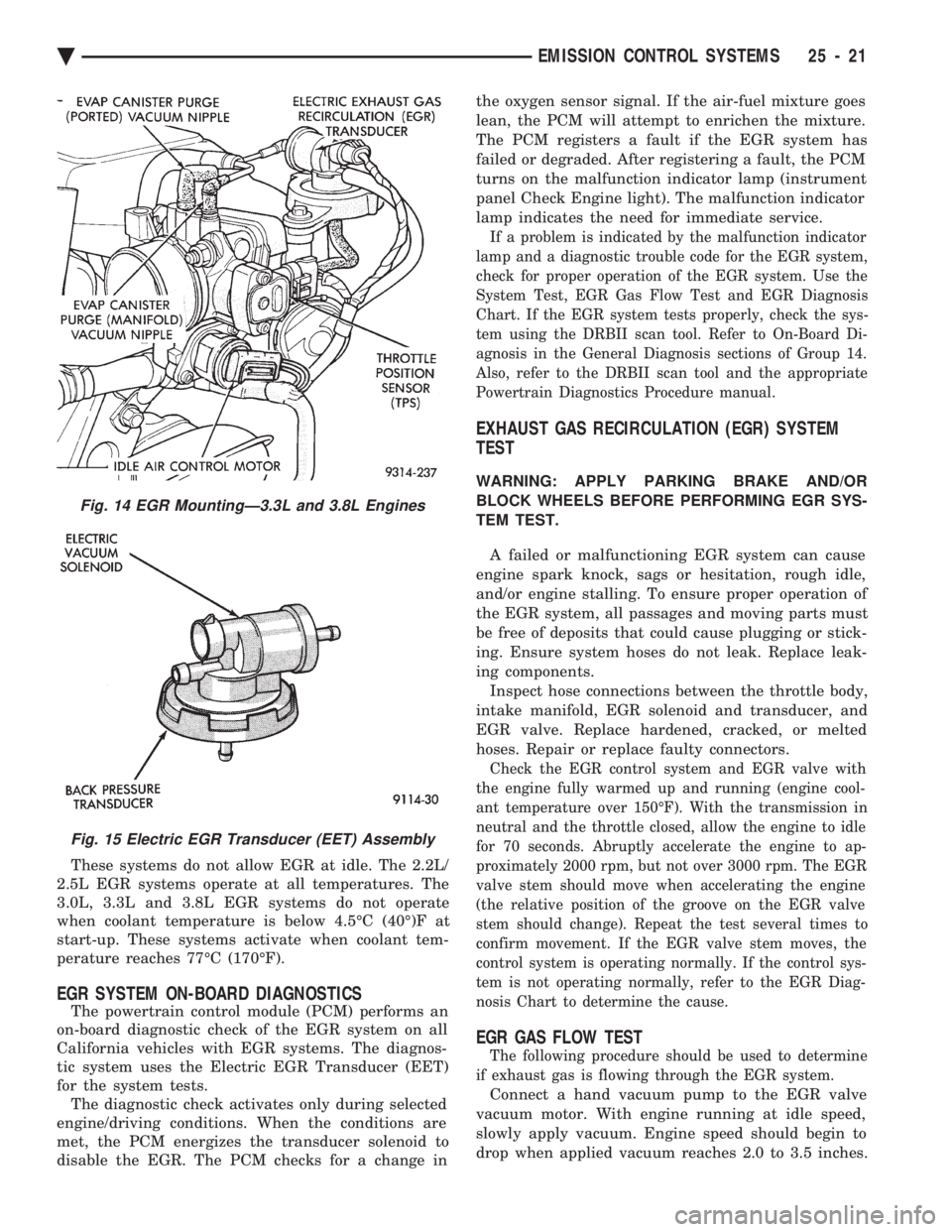
ing components. Inspect hose connections between the throttle body,
intake manifold, EGR solenoid and transducer, and
EGR valve. Replace hardened, cracked, or melted
hoses. Repair or replace faulty connectors.
Check the EGR control system and EGR valve with
the engine fully warmed up and running (engine cool-
ant temperature over 150ÉF). With the transmission in
neutral and the throttle closed, allow the engine to idle
for 70 seconds. Abruptly accelerate the engine to ap-
proximately 2000 rpm, but not over 3000 rpm. The EGR
valve stem should move when accelerating the engine
(the relative position of the groove on the EGR valve
stem should change). Repeat the test several times to
confirm movement. If the EGR valve stem moves, the
control system is operating normally. If the control sys-
tem is not operating normally, refer to the EGR Diag-
nosis Chart to determine the cause.
EGR GAS FLOW TEST
The following procedure should be used to determine
if exhaust gas is flowing through the EGR system.
Connect a hand vacuum pump to the EGR valve
vacuum motor. With engine running at idle speed,
slowly apply vacuum. Engine speed should begin to
drop when applied vacuum reaches 2.0 to 3.5 inches.
Fig. 14 EGR MountingÐ3.3L and 3.8L Engines
Fig. 15 Electric EGR Transducer (EET) Assembly
Ä EMISSION CONTROL SYSTEMS 25 - 21