CHEVROLET PLYMOUTH ACCLAIM 1993 Service Manual
Manufacturer: CHEVROLET, Model Year: 1993, Model line: PLYMOUTH ACCLAIM, Model: CHEVROLET PLYMOUTH ACCLAIM 1993Pages: 2438, PDF Size: 74.98 MB
Page 1791 of 2438
CAUTION: When using the ASD Fuel System Test,
the Auto Shutdown (ASD) Relay remains energized
for either 7 minutes, until the test is stopped, or un-
til the ignition switch is turned to the Off position. (6) With the ignition key in ON position, access
the DRBII scan tool ASD Fuel System Test to pres-
surize the fuel system. Check for leaks. (7) Reinstall air cleaner assembly.
FUEL PRESSURE REGULATOR
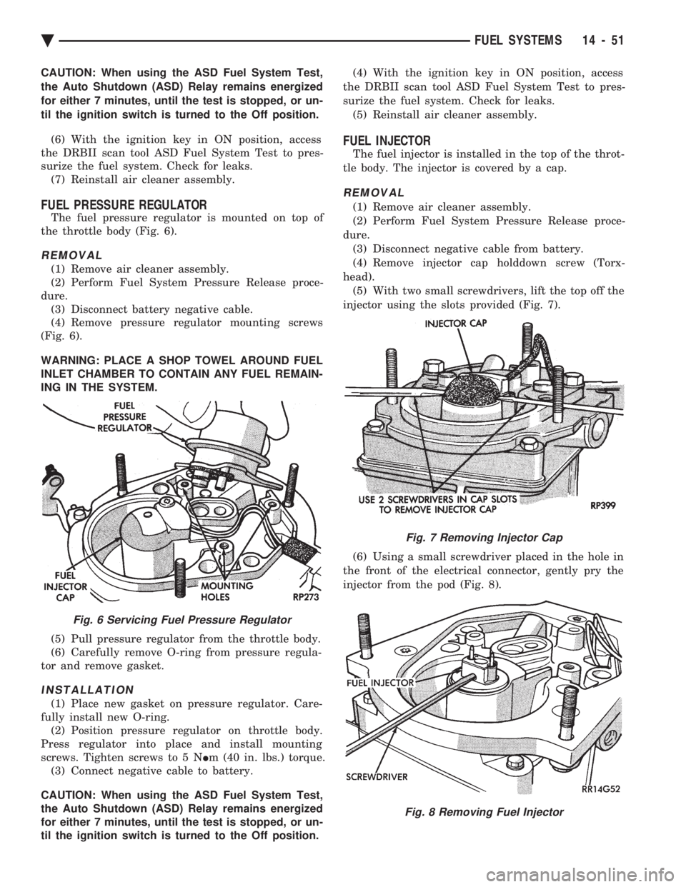
The fuel pressure regulator is mounted on top of
the throttle body (Fig. 6).
REMOVAL
(1) Remove air cleaner assembly.
(2) Perform Fuel System Pressure Release proce-
dure. (3) Disconnect battery negative cable.
(4) Remove pressure regulator mounting screws
(Fig. 6).
WARNING: PLACE A SHOP TOWEL AROUND FUEL
INLET CHAMBER TO CONTAIN ANY FUEL REMAIN-
ING IN THE SYSTEM.
(5) Pull pressure regulator from the throttle body.
(6) Carefully remove O-ring from pressure regula-
tor and remove gasket.
INSTALLATION
(1) Place new gasket on pressure regulator. Care-
fully install new O-ring. (2) Position pressure regulator on throttle body.
Press regulator into place and install mounting
screws. Tighten screws to 5 N Im (40 in. lbs.) torque.
(3) Connect negative cable to battery.
CAUTION: When using the ASD Fuel System Test,
the Auto Shutdown (ASD) Relay remains energized
for either 7 minutes, until the test is stopped, or un-
til the ignition switch is turned to the Off position. (4) With the ignition key in ON position, access
the DRBII scan tool ASD Fuel System Test to pres-
surize the fuel system. Check for leaks. (5) Reinstall air cleaner assembly.
FUEL INJECTOR
The fuel injector is installed in the top of the throt-
tle body. The injector is covered by a cap.
REMOVAL
(1) Remove air cleaner assembly.
(2) Perform Fuel System Pressure Release proce-
dure. (3) Disconnect negative cable from battery.
(4) Remove injector cap holddown screw (Torx-
head). (5) With two small screwdrivers, lift the top off the
injector using the slots provided (Fig. 7).
(6) Using a small screwdriver placed in the hole in
the front of the electrical connector, gently pry the
injector from the pod (Fig. 8).
Fig. 6 Servicing Fuel Pressure Regulator
Fig. 7 Removing Injector Cap
Fig. 8 Removing Fuel Injector
Ä FUEL SYSTEMS 14 - 51
Page 1792 of 2438
(7) Ensure the injector lower O-ring has been re-
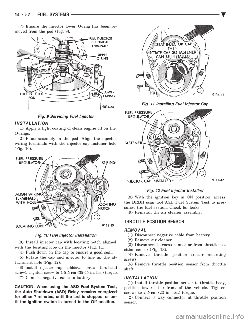
moved from the pod (Fig. 9).
INSTALLATION
(1) Apply a light coating of clean engine oil on the
O-rings. (2) Place assembly in the pod. Align the injector
wiring terminals with the injector cap fastener hole
(Fig. 10).
(3) Install injector cap with locating notch aligned
with the locating lobe on the injector (Fig. 11). (4) Push down on the cap to ensure a good seal.
(5) Rotate the cap and injector to line up the at-
tachment hole (Fig. 12).
(6) Install injector cap holddown screw (torx-head
screw). Tighten screw to 4-5 N Im (35-45 in. lbs.) torque.
(7) Connect negative cable to battery.
CAUTION: When using the ASD Fuel System Test,
the Auto Shutdown (ASD) Relay remains energized
for either 7 minutes, until the test is stopped, or un-
til the ignition switch is turned to the Off position. (8) With the ignition key in ON position, access
the DRBII scan tool ASD Fuel System Test to pres-
surize the fuel system. Check for leaks. (9) Reinstall the air cleaner assembly.
THROTTLE POSITION SENSOR
REMOVAL
(1) Disconnect negative cable from battery.
(2) Remove air cleaner.
(3) Disconnect harness connector from throttle po-
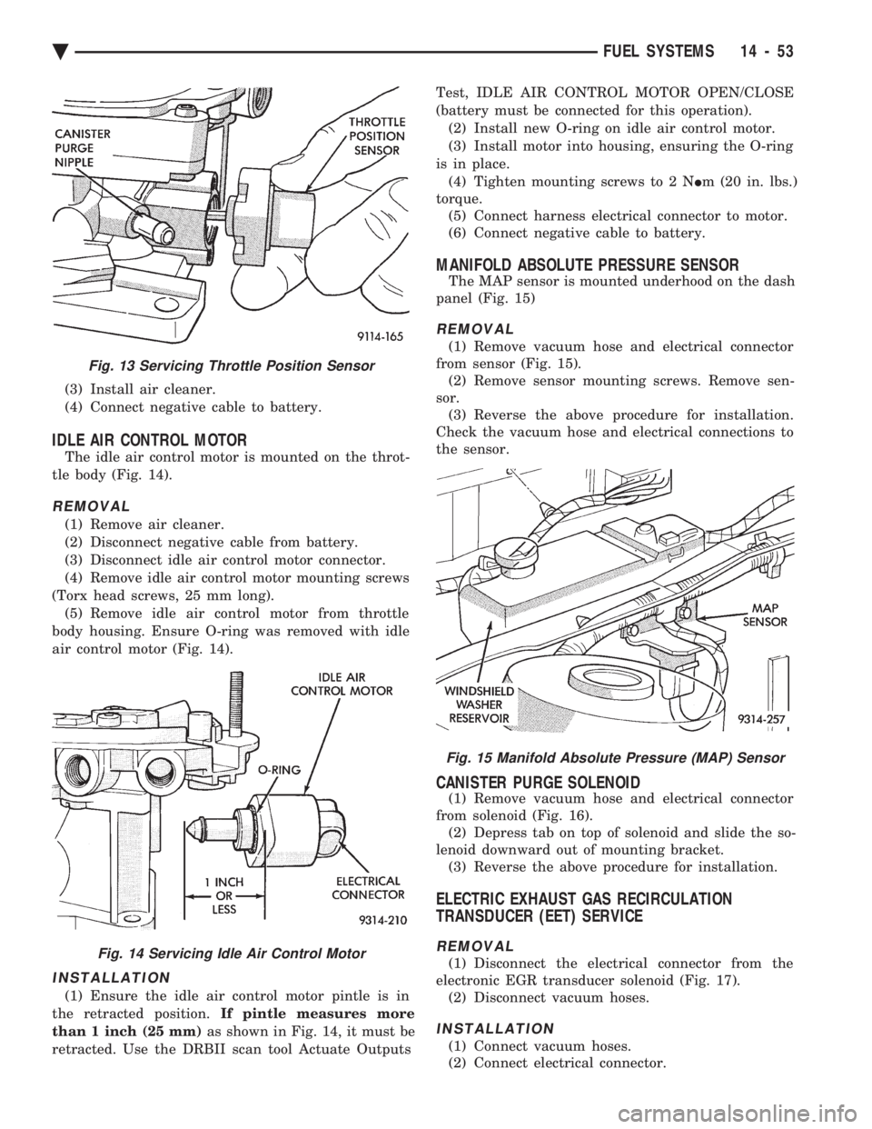
sition sensor (Fig. 13). (4) Remove throttle position sensor mounting
screws. (5) Remove throttle position sensor from throttle
shaft.
INSTALLATION
(1) Install throttle position sensor to throttle body,
position toward the front of the vehicle. Tighten
screws to 2 N Im (20 in. lbs.) torque.
(2) Connect 3 way connector at throttle position
sensor.
Fig. 9 Servicing Fuel Injector
Fig. 10 Fuel Injector Installation
Fig. 11 Installing Fuel Injector Cap
Fig. 12 Fuel Injector Installed
14 - 52 FUEL SYSTEMS Ä
Page 1793 of 2438
(3) Install air cleaner.
(4) Connect negative cable to battery.
IDLE AIR CONTROL MOTOR
The idle air control motor is mounted on the throt-
tle body (Fig. 14).
REMOVAL
(1) Remove air cleaner.
(2) Disconnect negative cable from battery.
(3) Disconnect idle air control motor connector.
(4) Remove idle air control motor mounting screws
(Torx head screws, 25 mm long). (5) Remove idle air control motor from throttle
body housing. Ensure O-ring was removed with idle
air control motor (Fig. 14).
INSTALLATION
(1) Ensure the idle air control motor pintle is in
the retracted position. If pintle measures more
than 1 inch (25 mm) as shown in Fig. 14, it must be
retracted. Use the DRBII scan tool Actuate Outputs Test, IDLE AIR CONTROL MOTOR OPEN/CLOSE
(battery must be connected for this operation). (2) Install new O-ring on idle air control motor.
(3) Install motor into housing, ensuring the O-ring
is in place. (4) Tighten mounting screws to 2 N Im (20 in. lbs.)
torque. (5) Connect harness electrical connector to motor.
(6) Connect negative cable to battery.
MANIFOLD ABSOLUTE PRESSURE SENSOR
The MAP sensor is mounted underhood on the dash
panel (Fig. 15)
REMOVAL
(1) Remove vacuum hose and electrical connector
from sensor (Fig. 15). (2) Remove sensor mounting screws. Remove sen-
sor. (3) Reverse the above procedure for installation.
Check the vacuum hose and electrical connections to
the sensor.
CANISTER PURGE SOLENOID
(1) Remove vacuum hose and electrical connector
from solenoid (Fig. 16). (2) Depress tab on top of solenoid and slide the so-
lenoid downward out of mounting bracket. (3) Reverse the above procedure for installation.
ELECTRIC EXHAUST GAS RECIRCULATION
TRANSDUCER (EET) SERVICE
REMOVAL
(1) Disconnect the electrical connector from the
electronic EGR transducer solenoid (Fig. 17). (2) Disconnect vacuum hoses.
INSTALLATION
(1) Connect vacuum hoses.
(2) Connect electrical connector.
Fig. 15 Manifold Absolute Pressure (MAP) Sensor
Fig. 13 Servicing Throttle Position Sensor
Fig. 14 Servicing Idle Air Control Motor
Ä FUEL SYSTEMS 14 - 53
Page 1794 of 2438
PCM SERVICE
(1) Remove air cleaner duct from PCM.
(2) Remove battery.
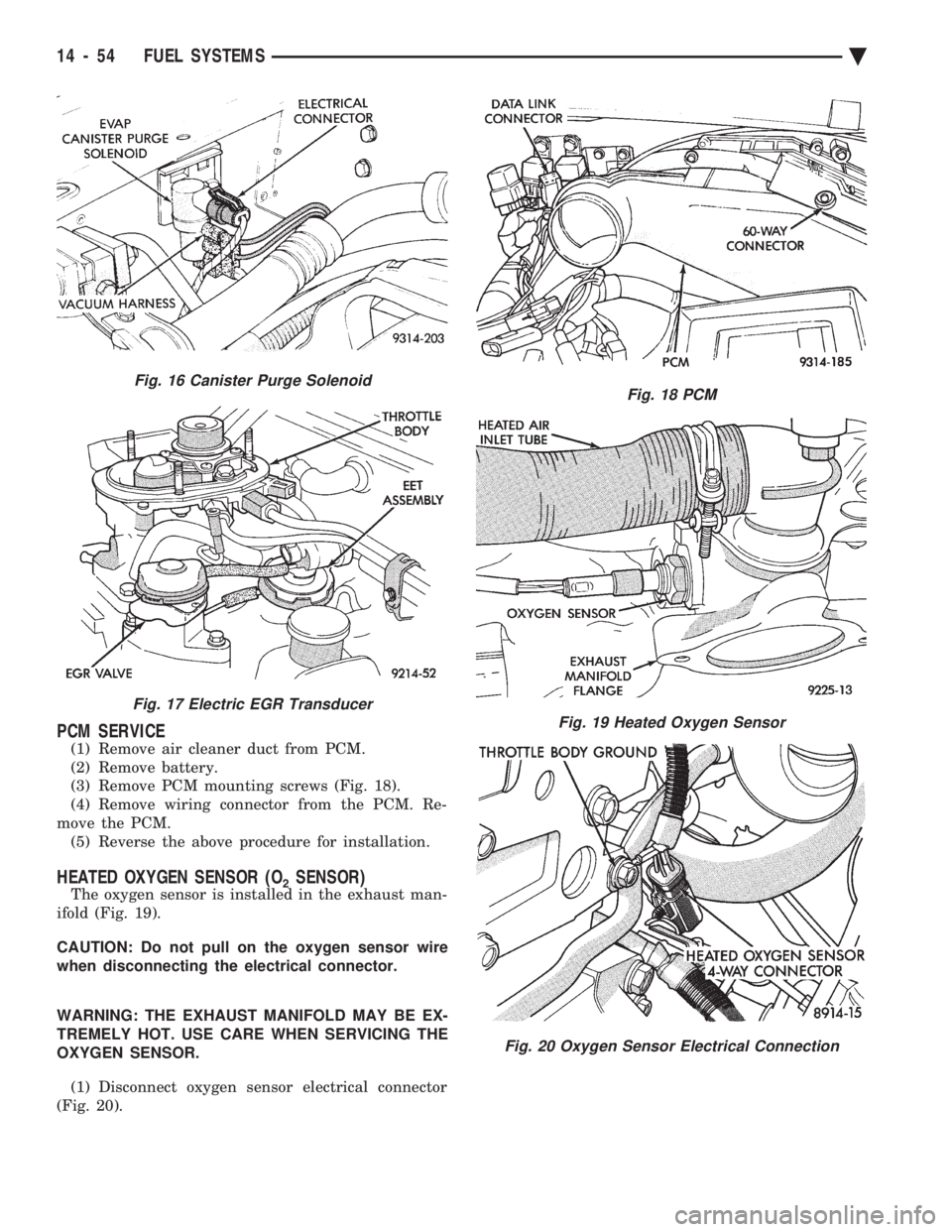
(3) Remove PCM mounting screws (Fig. 18).
(4) Remove wiring connector from the PCM. Re-
move the PCM. (5) Reverse the above procedure for installation.
HEATED OXYGEN SENSOR (O2SENSOR)
The oxygen sensor is installed in the exhaust man-
ifold (Fig. 19).
CAUTION: Do not pull on the oxygen sensor wire
when disconnecting the electrical connector.
WARNING: THE EXHAUST MANIFOLD MAY BE EX-
TREMELY HOT. USE CARE WHEN SERVICING THE
OXYGEN SENSOR.
(1) Disconnect oxygen sensor electrical connector
(Fig. 20).
Fig. 18 PCM
Fig. 19 Heated Oxygen Sensor
Fig. 20 Oxygen Sensor Electrical Connection
Fig. 16 Canister Purge Solenoid
Fig. 17 Electric EGR Transducer
14 - 54 FUEL SYSTEMS Ä
Page 1795 of 2438
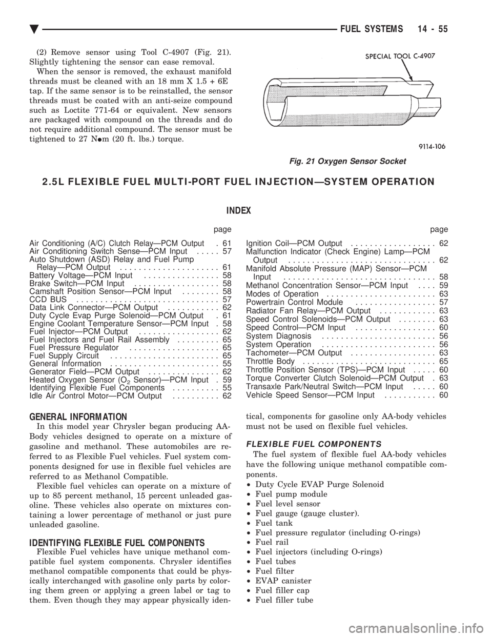
(2) Remove sensor using Tool C-4907 (Fig. 21).
Slightly tightening the sensor can ease removal. When the sensor is removed, the exhaust manifold
threads must be cleaned with an 18 mm X 1.5 + 6E
tap. If the same sensor is to be reinstalled, the sensor
threads must be coated with an anti-seize compound
such as Loctite 771-64 or equivalent. New sensors
are packaged with compound on the threads and do
not require additional compound. The sensor must be
tightened to 27 N Im (20 ft. lbs.) torque.
2.5L FLEXIBLE FUEL MULTI-PORT FUEL INJECTIONÐSYSTEM OPERATION
INDEX
page page
Air Conditioning (A/C) Clutch RelayÐPCM Output.61
Air Conditioning Switch SenseÐPCM Input ..... 57
Auto Shutdown (ASD) Relay and Fuel Pump RelayÐPCM Output ..................... 61
Battery VoltageÐPCM Input ................ 58
Brake SwitchÐPCM Input .................. 58
Camshaft Position SensorÐPCM Input ........ 58
CCD BUS .............................. 57
Data Link ConnectorÐPCM Output ........... 62
Duty Cycle Evap Purge SolenoidÐPCM Output . 61
Engine Coolant Temperature SensorÐPCM Input . 58
Fuel InjectorÐPCM Output ................. 62
Fuel Injectors and Fuel Rail Assembly ......... 65
Fuel Pressure Regulator ................... 65
Fuel Supply Circuit ....................... 65
General Information ....................... 55
Generator FieldÐPCM Output ............... 62
Heated Oxygen Sensor (O
2Sensor)ÐPCM Input . 59
Identifying Flexible Fuel Components .......... 55
Idle Air Control MotorÐPCM Output .......... 62 Ignition CoilÐPCM Output
.................. 62
Malfunction Indicator (Check Engine) LampÐPCM Output ............................... 62
Manifold Absolute Pressure (MAP) SensorÐPCM Input ................................ 58
Methanol Concentration SensorÐPCM Input .... 59
Modes of Operation ....................... 63
Powertrain Control Module ................. 57
Radiator Fan RelayÐPCM Output ............ 63
Speed Control SolenoidsÐPCM Output ........ 63
Speed ControlÐPCM Input ................. 60
System Diagnosis ........................ 56
System Operation ........................ 56
TachometerÐPCM Output .................. 63
Throttle Body ............................ 65
Throttle Position Sensor (TPS)ÐPCM Input ..... 60
Torque Converter Clutch SolenoidÐPCM Output . 63
Transaxle Park/Neutral SwitchÐPCM Input ..... 60
Vehicle Speed SensorÐPCM Input ........... 60
GENERAL INFORMATION
In this model year Chrysler began producing AA-
Body vehicles designed to operate on a mixture of
gasoline and methanol. These automobiles are re-
ferred to as Flexible Fuel vehicles. Fuel system com-
ponents designed for use in flexible fuel vehicles are
referred to as Methanol Compatible. Flexible fuel vehicles can operate on a mixture of
up to 85 percent methanol, 15 percent unleaded gas-
oline. These vehicles also operate on mixtures con-
taining a lower percentage of methanol or just pure
unleaded gasoline.
IDENTIFYING FLEXIBLE FUEL COMPONENTS
Flexible Fuel vehicles have unique methanol com-
patible fuel system components. Chrysler identifies
methanol compatible components that could be phys-
ically interchanged with gasoline only parts by color-
ing them green or applying a green label or tag to
them. Even though they may appear physically iden- tical, components for gasoline only AA-body vehicles
must not be used on flexible fuel vehicles.
FLEXIBLE FUEL COMPONENTS
The fuel system of flexible fuel AA-body vehicles
have the following unique methanol compatible com-
ponents.
² Duty Cycle EVAP Purge Solenoid
² Fuel pump module
² Fuel level sensor
² Fuel gauge (gauge cluster).
² Fuel tank
² Fuel pressure regulator (including O-rings)
² Fuel rail
² Fuel injectors (including O-rings)
² Fuel tubes
² Fuel filter
² EVAP canister
² Fuel filler cap
² Fuel filler tube
Fig. 21 Oxygen Sensor Socket
Ä FUEL SYSTEMS 14 - 55
Page 1796 of 2438
² Methanol Concentration Sensor
² Pressure relief/Rollover valve
² PCV Valve
² All fuel system and emission system hoses and
tubes
SYSTEM OPERATION
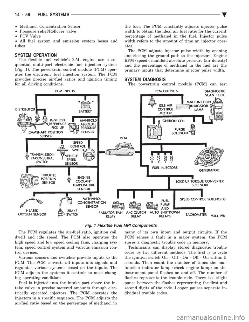
The flexible fuel vehicle's 2.5L engine use a se-
quential multi-port electronic fuel injection system
(Fig. 1). The powertrain control module (PCM) oper-
ates the electronic fuel injection system. The PCM
provides precise air/fuel ratios and ignition timing
for all driving conditions.
The PCM regulates the air-fuel ratio, ignition coil
dwell and idle speed. The PCM also operates the
high speed and low speed cooling fans, charging sys-
tem, speed control system and various emission con-
trol devices. Various sensors and switches provide inputs to the
PCM. The PCM converts all inputs into signals and
regulates various systems based on the inputs. The
PCM adjusts the systems it controls to meet chang-
ing operating conditions. Fuel is injected into the intake port above the in-
take valve in precise metered amounts through elec-
trically operated injectors. The PCM operates the
injectors in a specific sequence. The PCM adjusts the
air/fuel ratio based on the percentage of methanol in the fuel. The PCM constantly adjusts injector pulse
width to obtain the ideal air fuel ratio for the current
percentage of methanol in the fuel. Injector pulse
width refers to the amount of time an injector oper-
ates. The PCM adjusts injector pulse width by opening
and closing the ground path to the injectors. Engine
RPM (speed), manifold absolute pressure (air density)
and the percentage of methanol in the fuel are the
primary inputs that determine injector pulse width.
SYSTEM DIAGNOSIS
The powertrain control module (PCM) can test
many of its own input and output circuits. If the
PCM senses a fault in a major system, the PCM
stores a diagnostic trouble code in memory. Technicians can display stored diagnostic trouble
codes by two different methods. The first is to cycle
the ignition switch On - Off - On - Off - On within 5
seconds. Then count the number of times the mal-
function indicator lamp (check engine lamp) on the
instrument panel flashes on and off. The number of
flashes represents the trouble code. There is a slight
pause between the flashes representing the first and
second digits of the code. Longer pauses separate in-
dividual trouble codes.
Fig. 1 Flexible Fuel MPI Components
14 - 56 FUEL SYSTEMS Ä
Page 1797 of 2438
The second method of reading diagnostic trouble
codes uses the DRBII scan tool. For diagnostic trou-
ble code information, refer to the On-Board Diagnos-
tics section in this group.
CCD BUS
Various modules exchange information through a
communications port called the CCD Bus. The pow-
ertrain control module transmits vehicle load data on
the CCD Bus.
POWERTRAIN CONTROL MODULE
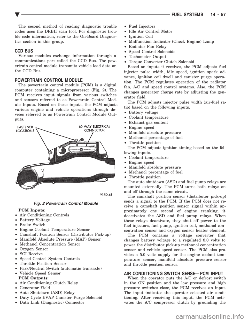
The powertrain control module (PCM) is a digital
computer containing a microprocessor (Fig. 2). The
PCM receives input signals from various switches
and sensors referred to as Powertrain Control Mod-
ule Inputs. Based on these inputs, the PCM adjusts
various engine and vehicle operations through de-
vices referred to as Powertrain Control Module Out-
puts.
PCM Inputs:
² Air Conditioning Controls
² Battery Voltage
² Brake Switch
² Engine Coolant Temperature Sensor
² Camshaft Position Sensor (Distributor Pick-up)
² Manifold Absolute Pressure (MAP) Sensor
² Methanol Concentration Sensor
² Oxygen Sensor
² SCI Receive
² Speed Control System Controls
² Throttle Position Sensor
² Park/Neutral Switch (automatic transaxle)
² Vehicle Speed Sensor
PCM Outputs:
² Air Conditioning Clutch Relay
² Generator Field
² Auto Shutdown (ASD) Relay
² Duty Cycle EVAP Canister Purge Solenoid
² Data Link (Diagnostic) Connector ²
Fuel Injectors
² Idle Air Control Motor
² Ignition Coil
² Malfunction Indicator (Check Engine) Lamp
² Radiator Fan Relay
² Speed Control Solenoids
² Tachometer Output
² Torque Converter Clutch Solenoid
Based on inputs it receives, the PCM adjusts fuel
injector pulse width, idle speed, ignition spark ad-
vance, ignition coil dwell and canister purge opera-
tion. The PCM regulates operation of the radiator
fan, A/C and speed control systems. Also, the PCM
changes generator charge rate by adjusting the gen-
erator field. The PCM adjusts injector pulse width (air-fuel ra-
tio) based on the following inputs.
² Battery voltage
² Coolant temperature
² Exhaust gas content
² Engine speed
² Manifold absolute pressure
² Methanol percentage of fuel
² Throttle position
The PCM adjusts ignition timing based on the fol-
lowing inputs.
² Coolant temperature
² Engine speed
² Manifold absolute pressure
² Methanol percentage of fuel
² Throttle position
The auto shutdown (ASD) and fuel pump relays are
mounted externally. The PCM turns both relays on
and off through the same circuit. The camshaft position sensor (distributor pick-up)
sends a signal to the PCM. If the PCM does not re-
ceive a camshaft position sensor signal within ap-
proximately one second of engine cranking, it
deactivates the ASD and fuel pump relays. When
these relays deactivate, they shut off power to the
fuel injectors, fuel pump, ignition coil, methanol con-
centration sensor and oxygen sensor heater element. The PCM contains a voltage converter that
changes battery voltage to a regulated 8.0 volts to
power the distributor pick-up methanol concentration
sensor and vehicle speed sensor. The PCM also pro-
vides a 5.0 volts supply for the engine coolant tem-
perature sensor, manifold absolute pressure sensor
and throttle position sensor.
AIR CONDITIONING SWITCH SENSEÐPCM INPUT
When the operator puts the A/C or defrost switch
in the ON position and the low pressure and high
pressure switches close, the PCM receives an input.
The input indicates the operator selected air condi-
tioning. After receiving this input, the PCM acti-
vates the A/C compressor clutch by grounding the
Fig. 2 Powertrain Control Module
Ä FUEL SYSTEMS 14 - 57
Page 1798 of 2438
A/C clutch relay. To compensate for increased engine
load, the PCM also adjusts idle speed to a scheduled
RPM.
BATTERY VOLTAGEÐPCM INPUT
The powertrain control module (PCM) monitors the
battery voltage input to determine fuel injector pulse
width and generator field control. If battery voltage
is low, the PCM increases injector pulse width to
compensate.
BRAKE SWITCHÐPCM INPUT
When the brake switch activates, the powertrain
control module (PCM) receives an input indicating
that the brakes are being applied. After receiving the
input, the PCM vents the speed control servo. Vent-
ing the servo turns the speed control system off.
ENGINE COOLANT TEMPERATURE SENSORÐPCM
INPUT
The coolant temperature sensor is installed behind
the thermostat housing and ignition coil in the ther-
mostat housing (hot box). The PCM supplies 5 volts
to the coolant temperature sensor. The sensor pro-
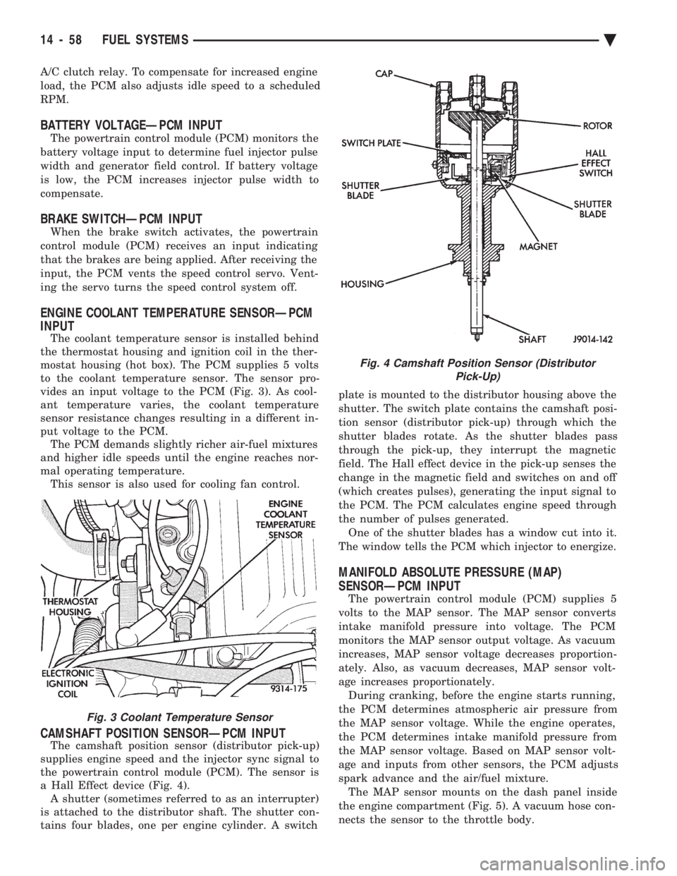
vides an input voltage to the PCM (Fig. 3). As cool-
ant temperature varies, the coolant temperature
sensor resistance changes resulting in a different in-
put voltage to the PCM. The PCM demands slightly richer air-fuel mixtures
and higher idle speeds until the engine reaches nor-
mal operating temperature. This sensor is also used for cooling fan control.
CAMSHAFT POSITION SENSORÐPCM INPUT
The camshaft position sensor (distributor pick-up)
supplies engine speed and the injector sync signal to
the powertrain control module (PCM). The sensor is
a Hall Effect device (Fig. 4). A shutter (sometimes referred to as an interrupter)
is attached to the distributor shaft. The shutter con-
tains four blades, one per engine cylinder. A switch plate is mounted to the distributor housing above the
shutter. The switch plate contains the camshaft posi-
tion sensor (distributor pick-up) through which the
shutter blades rotate. As the shutter blades pass
through the pick-up, they interrupt the magnetic
field. The Hall effect device in the pick-up senses the
change in the magnetic field and switches on and off
(which creates pulses), generating the input signal to
the PCM. The PCM calculates engine speed through
the number of pulses generated. One of the shutter blades has a window cut into it.
The window tells the PCM which injector to energize.
MANIFOLD ABSOLUTE PRESSURE (MAP)
SENSORÐPCM INPUT
The powertrain control module (PCM) supplies 5
volts to the MAP sensor. The MAP sensor converts
intake manifold pressure into voltage. The PCM
monitors the MAP sensor output voltage. As vacuum
increases, MAP sensor voltage decreases proportion-
ately. Also, as vacuum decreases, MAP sensor volt-
age increases proportionately. During cranking, before the engine starts running,
the PCM determines atmospheric air pressure from
the MAP sensor voltage. While the engine operates,
the PCM determines intake manifold pressure from
the MAP sensor voltage. Based on MAP sensor volt-
age and inputs from other sensors, the PCM adjusts
spark advance and the air/fuel mixture. The MAP sensor mounts on the dash panel inside
the engine compartment (Fig. 5). A vacuum hose con-
nects the sensor to the throttle body.
Fig. 3 Coolant Temperature Sensor
Fig. 4 Camshaft Position Sensor (Distributor Pick-Up)
14 - 58 FUEL SYSTEMS Ä
Page 1799 of 2438
METHANOL CONCENTRATION SENSORÐPCM
INPUT
The methanol concentration sensor contains a mi-
croprocessor that determines the percentage of gaso-
line and methanol in the fuel system. From the
methanol concentration sensor input, the powertrain
control module (PCM) determines the amount of
methanol in the fuel. The vehicle can operate on a
mixtures up to 85 percent methanol, 15 percent gas-
oline. The PCM supplies 8 volts to the methanol concen-
tration sensor. The methanol concentration sensor
output voltages varies with the percent of methanol
in the fuel system. The sensor output voltage (input
for PCM) ranges from 0.5 volts for pure gasoline to
4.50 volts for 85 percent methanol. For two seconds
at key ON when the operator starts the vehicle, the
sensor calibrates the PCM. During the calibration
period the sensor sends 4.45 volts to the PCM as a
correction factor. The methanol concentration sensor has a built-in
shutdown capability. If the sensor shuts down, the
PCM defaults to the previous learned value (output
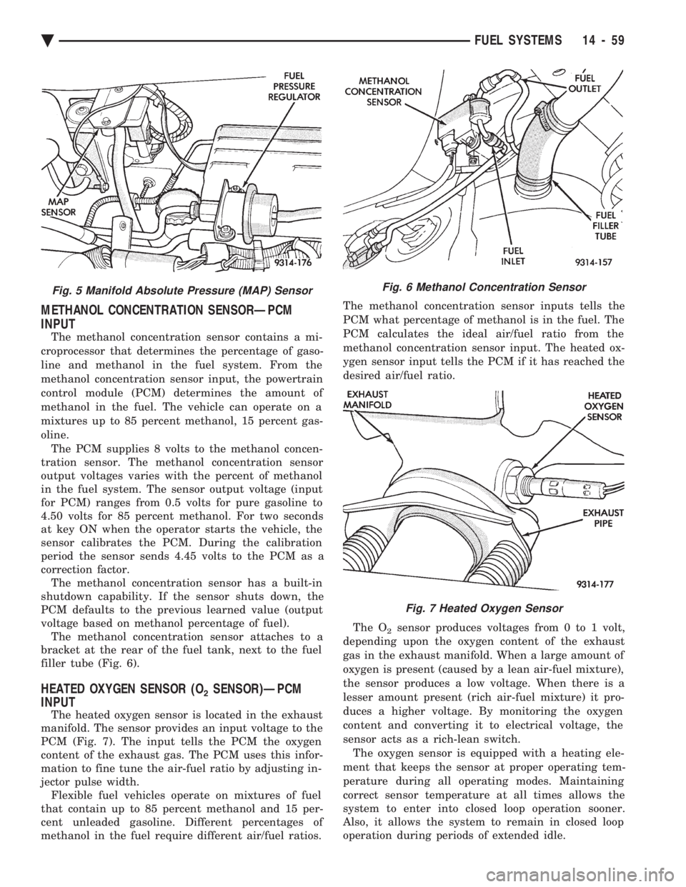
voltage based on methanol percentage of fuel). The methanol concentration sensor attaches to a
bracket at the rear of the fuel tank, next to the fuel
filler tube (Fig. 6).
HEATED OXYGEN SENSOR (O2SENSOR)ÐPCM
INPUT
The heated oxygen sensor is located in the exhaust
manifold. The sensor provides an input voltage to the
PCM (Fig. 7). The input tells the PCM the oxygen
content of the exhaust gas. The PCM uses this infor-
mation to fine tune the air-fuel ratio by adjusting in-
jector pulse width. Flexible fuel vehicles operate on mixtures of fuel
that contain up to 85 percent methanol and 15 per-
cent unleaded gasoline. Different percentages of
methanol in the fuel require different air/fuel ratios. The methanol concentration sensor inputs tells the
PCM what percentage of methanol is in the fuel. The
PCM calculates the ideal air/fuel ratio from the
methanol concentration sensor input. The heated ox-
ygen sensor input tells the PCM if it has reached the
desired air/fuel ratio.
The O
2sensor produces voltages from 0 to 1 volt,
depending upon the oxygen content of the exhaust
gas in the exhaust manifold. When a large amount of
oxygen is present (caused by a lean air-fuel mixture),
the sensor produces a low voltage. When there is a
lesser amount present (rich air-fuel mixture) it pro-
duces a higher voltage. By monitoring the oxygen
content and converting it to electrical voltage, the
sensor acts as a rich-lean switch. The oxygen sensor is equipped with a heating ele-
ment that keeps the sensor at proper operating tem-
perature during all operating modes. Maintaining
correct sensor temperature at all times allows the
system to enter into closed loop operation sooner.
Also, it allows the system to remain in closed loop
operation during periods of extended idle.
Fig. 5 Manifold Absolute Pressure (MAP) SensorFig. 6 Methanol Concentration Sensor
Fig. 7 Heated Oxygen Sensor
Ä FUEL SYSTEMS 14 - 59
Page 1800 of 2438
In Closed Loop operation the PCM monitors the O2
sensor input (along with other inputs) and adjusts
the injector pulse width accordingly. During Open
Loop operation the PCM ignores the O
2sensor input.
In Open Loop, the PCM adjusts injector pulse width
based on a preprogrammed (fixed) oxygen sensor in-
put value and other inputs.
SPEED CONTROLÐPCM INPUT
The speed control system provides four separate
voltages (inputs) to the PCM. The voltages corre-
spond to the On/Off, Set, and Resume. The speed control ON voltage informs the PCM
that the speed control system has been activated.
The speed control SET voltage informs the PCM that
a fixed vehicle speed has been selected. The speed
control RESUME voltage indicates the previous fixed
speed is requested. The speed control OFF voltage
tells the PCM that the speed control system has de-
activated. Refer to Group 8H for further speed con-
trol information.
TRANSAXLE PARK/NEUTRAL SWITCHÐPCM
INPUT
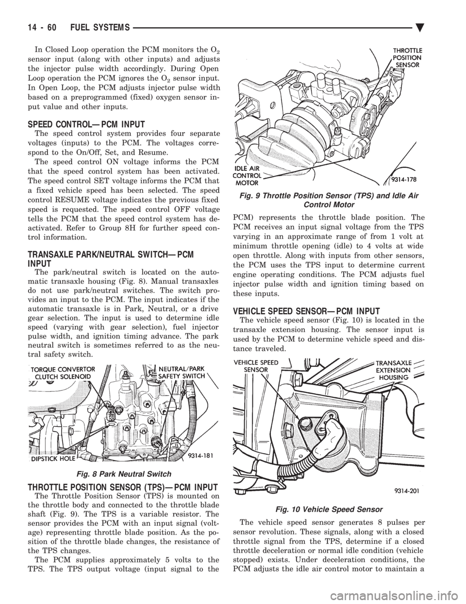
The park/neutral switch is located on the auto-
matic transaxle housing (Fig. 8). Manual transaxles
do not use park/neutral switches. The switch pro-
vides an input to the PCM. The input indicates if the
automatic transaxle is in Park, Neutral, or a drive
gear selection. The input is used to determine idle
speed (varying with gear selection), fuel injector
pulse width, and ignition timing advance. The park
neutral switch is sometimes referred to as the neu-
tral safety switch.
THROTTLE POSITION SENSOR (TPS)ÐPCM INPUT
The Throttle Position Sensor (TPS) is mounted on
the throttle body and connected to the throttle blade
shaft (Fig. 9). The TPS is a variable resistor. The
sensor provides the PCM with an input signal (volt-
age) representing throttle blade position. As the po-
sition of the throttle blade changes, the resistance of
the TPS changes. The PCM supplies approximately 5 volts to the
TPS. The TPS output voltage (input signal to the PCM) represents the throttle blade position. The
PCM receives an input signal voltage from the TPS
varying in an approximate range of from 1 volt at
minimum throttle opening (idle) to 4 volts at wide
open throttle. Along with inputs from other sensors,
the PCM uses the TPS input to determine current
engine operating conditions. The PCM adjusts fuel
injector pulse width and ignition timing based on
these inputs.
VEHICLE SPEED SENSORÐPCM INPUT
The vehicle speed sensor (Fig. 10) is located in the
transaxle extension housing. The sensor input is
used by the PCM to determine vehicle speed and dis-
tance traveled.
The vehicle speed sensor generates 8 pulses per
sensor revolution. These signals, along with a closed
throttle signal from the TPS, determine if a closed
throttle deceleration or normal idle condition (vehicle
stopped) exists. Under deceleration conditions, the
PCM adjusts the idle air control motor to maintain a
Fig. 8 Park Neutral Switch
Fig. 9 Throttle Position Sensor (TPS) and Idle Air Control Motor
Fig. 10 Vehicle Speed Sensor
14 - 60 FUEL SYSTEMS Ä