oil type CHEVROLET PLYMOUTH ACCLAIM 1993 User Guide
[x] Cancel search | Manufacturer: CHEVROLET, Model Year: 1993, Model line: PLYMOUTH ACCLAIM, Model: CHEVROLET PLYMOUTH ACCLAIM 1993Pages: 2438, PDF Size: 74.98 MB
Page 220 of 2438
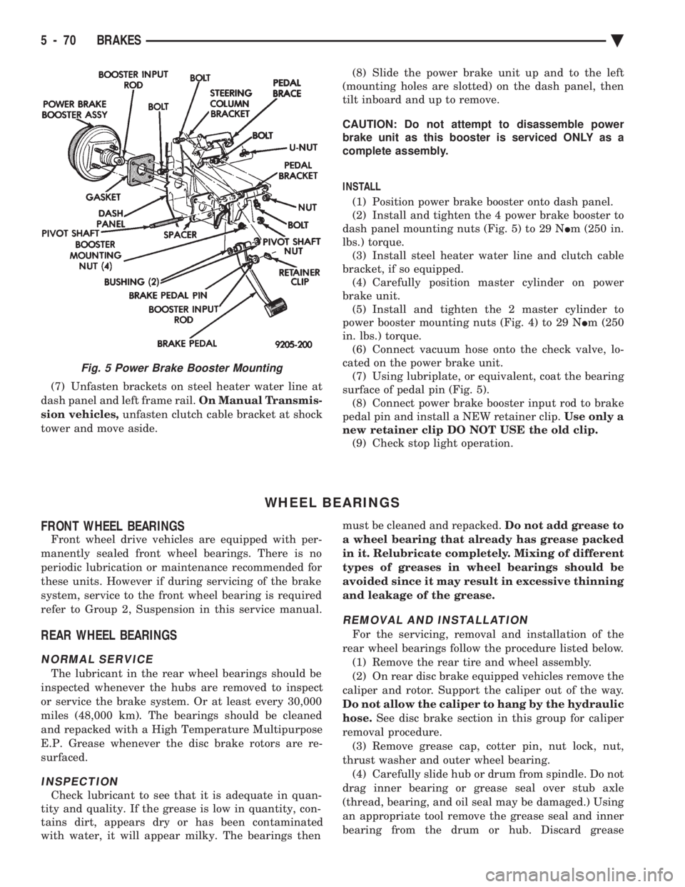
(7) Unfasten brackets on steel heater water line at
dash panel and left frame rail. On Manual Transmis-
sion vehicles, unfasten clutch cable bracket at shock
tower and move aside. (8) Slide the power brake unit up and to the left
(mounting holes are slotted) on the dash panel, then
tilt inboard and up to remove.
CAUTION: Do not attempt to disassemble power
brake unit as this booster is serviced ONLY as a
complete assembly.
INSTALL (1) Position power brake booster onto dash panel.
(2) Install and tighten the 4 power brake booster to
dash panel mounting nuts (Fig. 5) to 29 N Im (250 in.
lbs.) torque. (3) Install steel heater water line and clutch cable
bracket, if so equipped. (4) Carefully position master cylinder on power
brake unit. (5) Install and tighten the 2 master cylinder to
power booster mounting nuts (Fig. 4) to 29 N Im (250
in. lbs.) torque. (6) Connect vacuum hose onto the check valve, lo-
cated on the power brake unit. (7) Using lubriplate, or equivalent, coat the bearing
surface of pedal pin (Fig. 5). (8) Connect power brake booster input rod to brake
pedal pin and install a NEW retainer clip. Use only a
new retainer clip DO NOT USE the old clip. (9) Check stop light operation.
WHEEL BEARINGS
FRONT WHEEL BEARINGS
Front wheel drive vehicles are equipped with per-
manently sealed front wheel bearings. There is no
periodic lubrication or maintenance recommended for
these units. However if during servicing of the brake
system, service to the front wheel bearing is required
refer to Group 2, Suspension in this service manual.
REAR WHEEL BEARINGS
NORMAL SERVICE
The lubricant in the rear wheel bearings should be
inspected whenever the hubs are removed to inspect
or service the brake system. Or at least every 30,000
miles (48,000 km). The bearings should be cleaned
and repacked with a High Temperature Multipurpose
E.P. Grease whenever the disc brake rotors are re-
surfaced.
INSPECTION
Check lubricant to see that it is adequate in quan-
tity and quality. If the grease is low in quantity, con-
tains dirt, appears dry or has been contaminated
with water, it will appear milky. The bearings then must be cleaned and repacked.
Do not add grease to
a wheel bearing that already has grease packed
in it. Relubricate completely. Mixing of different
types of greases in wheel bearings should be
avoided since it may result in excessive thinning
and leakage of the grease.
REMOVAL AND INSTALLATION
For the servicing, removal and installation of the
rear wheel bearings follow the procedure listed below. (1) Remove the rear tire and wheel assembly.
(2) On rear disc brake equipped vehicles remove the
caliper and rotor. Support the caliper out of the way.
Do not allow the caliper to hang by the hydraulic
hose. See disc brake section in this group for caliper
removal procedure. (3) Remove grease cap, cotter pin, nut lock, nut,
thrust washer and outer wheel bearing. (4) Carefully slide hub or drum from spindle. Do not
drag inner bearing or grease seal over stub axle
(thread, bearing, and oil seal may be damaged.) Using
an appropriate tool remove the grease seal and inner
bearing from the drum or hub. Discard grease
Fig. 5 Power Brake Booster Mounting
5 - 70 BRAKES Ä
Page 260 of 2438
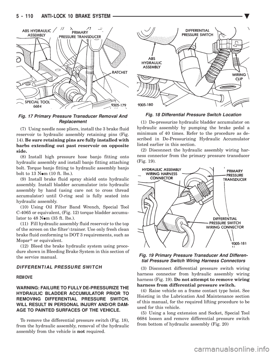
(7) Using needle nose pliers, install the 3 brake fluid
reservoir to hydraulic assembly retaining pins (Fig.
14). Be sure retaining pins are fully installed with
barbs extending out past reservoir on opposite
side. (8) Install high pressure hose banjo fitting onto
hydraulic assembly and install banjo fitting attaching
bolt. Torque banjo fitting to hydraulic assembly banjo
bolt to 13 N Im (10 ft. lbs.).
(9) Install brake fluid spray shield onto hydraulic
assembly. Install bladder accumulator into hydraulic
assembly by hand (using care not to cross thread
accumulator) until O-ring seal is fully seated into
hydraulic assembly. (10) Using Oil Filter Band Wrench, Special Tool
C-4065 or equivalent, (Fig. 12) torque bladder accumu-
lator to 48 N Im (35 ft. lbs.).
(11) Fill hydraulic assembly fluid reservoir to the top
of the screen on the filter rainer. Use only fresh clean
brake fluid conforming to DOT 3 requirements, such as
Mopar tor equivalent.
(12) Bleed the brake hydraulic system using proce-
dure shown in Bleeding Brake System in this section of
the service manual.
DIFFERENTIAL PRESSURE SWITCH
REMOVE
WARNING: FAILURE TO FULLY DE-PRESSURIZE THE
HYDRAULIC BLADDER ACCUMULATOR PRIOR TO
REMOVING DIFFERENTIAL PRESSURE SWITCH.
WILL RESULT IN PERSONAL INJURY AND/OR DAM-
AGE TO PAINTED SURFACES OF THE VEHICLE.
To remove the differential pressure switch (Fig. 18),
from the hydraulic assembly, removal of the hydraulic
assembly from the vehicle is notrequired. (1) De-pressurize hydraulic bladder accumulator on
hydraulic assembly by pumping the brake pedal a
minimum of 40 times. Refer to the procedure as de-
scribed in De-Pressurizing Hydraulic Accumulator
listed earlier in this section. (2) Disconnect the hydraulic assembly wiring har-
ness connector from the primary pressure transducer
(Fig. 19).
(3) Disconnect differential pressure switch wiring
harness connector from hydraulic assembly wiring
harness (Fig. 19). Do not attempt to remove wiring
harness from differential pressure switch. (4) Raise vehicle on a frame contact type hoist. See
Hoisting in the Lubrication And Maintenance section
of this manual, for the required lifting procedure to be
used for this vehicle. (5) Using a long extension and Socket, Special Tool
6684 loosen and remove differential pressure switch
from bottom of hydraulic assembly (Fig. 20)
Fig. 18 Differential Pressure Switch Location
Fig. 19 Primary Pressure Transducer And Differen- tial Pressure Switch Wiring Harness Connectors
Fig. 17 Primary Pressure Transducer Removal And Replacement
5 - 110 ANTI-LOCK 10 BRAKE SYSTEM Ä
Page 287 of 2438
BRAKES
CONTENTS
page page
BENDIX ANTILOCK 4 BRAKE SYSTEM ...... 12
GENERAL INFORMATION .................. 1 HYDRAULIC SYSTEM CONTROL VALVES . . . 10
SERVICE ADJUSTMENTS
.................. 3
GENERAL INFORMATION
Throughout this group, references may be made to
a particular vehicle by letter or number designation.
A chart showing the break down of these designa-
tions is included in the Introduction Section at the
front of this service manual. Standard brake equipment consists of:
² Double pin floating caliper disc front brakes.
² Rear automatic adjusting drum brakes.
² Differential valve with a brake warning switch.
² Master cylinder.
² Vacuum power booster.
² Double pin floating caliper rear disc brakes are
available on some models. The Bendix Antilock 4 Brake System, uses the fol-
lowing standard brake system components. Master
cylinder, power booster, caliper assemblies, braking
discs, pedal assembly, brake lines and hoses. The
unique parts of the Bendix Antilock 4 Brake System
consists of the following components, modulator as-
sembly, unique proportioning valves, unique junction
block, wheel speed sensors, tone wheels, and elec-
tronic control unit. These components will be de-
scribed in detail in the Bendix Antilock 4 Brake
System section in this service manual supplement. The hydraulic system, (Fig. 1) on the Bendix Anti-
lock 4 brake system is diagonally split. Diagonally
split hydraulic brake systems, have the left front and
right rear brakes on one hydraulic system and the
right front and left rear on the other. A diagonally
split hydraulic brake system, will maintain half of
the vehicles braking capability if there is a failure in
either half of the hydraulic system. The Bendix Antilock 4 Brake System uses two
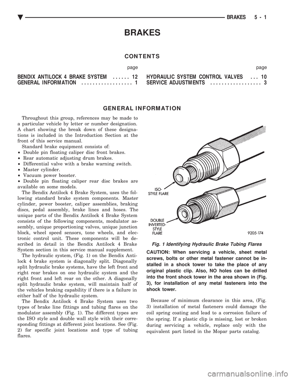
types of brake line fittings and tubing flares on the
modulator assembly (Fig. 1). The different types are
the ISO style and double wall style with their corre-
sponding fittings at different joint locations. See (Fig.
2) for specific joint locations and type of tubing
flares. CAUTION: When servicing a vehicle, sheet metal
screws, bolts or other metal fastener cannot be in-
stalled in a shock tower to take the place of any
original plastic clip. Also, NO holes can be drilled
into the front shock tower in the area shown in (Fig.
3), for installation of any metal fasteners into the
shock tower.
Because of minimum clearance in this area, (Fig.
3) installation of metal fasteners could damage the
coil spring coating and lead to a corrosion failure of
the spring. If a plastic clip is missing, lost or broken
during servicing a vehicle, replace only with the
equivalent part listed in the Mopar parts catalog.
Fig. 1 Identifying Hydraulic Brake Tubing Flares
Ä BRAKES 5 - 1
Page 289 of 2438
SERVICE ADJUSTMENTS INDEX
page page
Bleeding Bendix Antilock 4 Brake System ....... 3
Master Cylinder Fluid Level .................. 3 Testing for Fluid Contamination
............... 4
MASTER CYLINDER FLUID LEVEL
Check master cylinder reservoir brake fluid level a
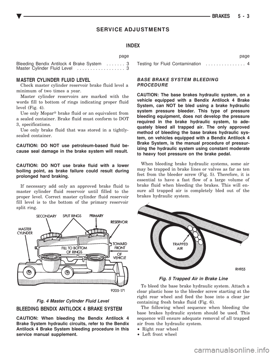
minimum of two times a year. Master cylinder reservoirs are marked with the
words fill to bottom of rings indicating proper fluid
level (Fig. 4). Use only Mopar tbrake fluid or an equivalent from
a sealed container. Brake fluid must conform to DOT
3, specifications. Use only brake fluid that was stored in a tightly-
sealed container.
CAUTION: DO NOT use petroleum-based fluid be-
cause seal damage in the brake system will result.
CAUTION: DO NOT use brake fluid with a lower
boiling point, as brake failure could result during
prolonged hard braking.
If necessary add only an approved brake fluid to
master cylinder fluid reservoir until filled to the
proper level. Correct master cylinder fluid reservoir
fill level is to the bottom of the primary reservoir
split ring.
BLEEDING BENDIX ANTILOCK 4 BRAKE SYSTEM
CAUTION: When bleeding the Bendix Antilock 4
Brake System hydraulic circuits, refer to the Bendix
Antilock 4 Brake System bleeding procedure in this
service manual supplement.
BASE BRAKE SYSTEM BLEEDING PROCEDURE
CAUTION: The base brakes hydraulic system, on a
vehicle equipped with a Bendix Antilock 4 Brake
System, can NOT be bled using a brake hydraulic
system pressure bleeder. This type of pressure
bleeding equipment, does not develop the pressure
required in the brake hydraulic system, to ade-
quately bleed all trapped air. The only approved
method of bleeding the base brakes hydraulic sys-
tem, on vehicles equipped with a Bendix Antilock 4
Brake System, is the manual procedure of pressur-
izing the hydraulic system using constant moderate
to heavy foot pressure on the brake pedal.
When bleeding brake hydraulic systems, some air
may be trapped in brake lines or valves as far as ten
feet from the bleeder screw (Fig. 5). Therefore, it is
essential to have a fast flow of a large volume of
brake fluid when bleeding the brakes. This will en-
sure all trapped air is completely bled out of the
brakes hydraulic system.
To bleed the base brake hydraulic system. Attach a
clear plastic hose to the bleeder screw starting at the
right rear wheel and feed the hose into a clear jar
containing fresh brake fluid (Fig. 6). The following wheel sequence when bleeding the
base brakes hydraulic system should be used. This
sequence will ensure adequate removal of all trapped
air from the hydraulic system.
² Right rear wheel
² Left front wheel
Fig. 4 Master Cylinder Fluid Level
Fig. 5 Trapped Air in Brake Line
Ä BRAKES 5 - 3
Page 311 of 2438
LATCHING VERSUS NON-LATCHING ABS FAULTS
Some faults detected by the CAB are latching; the
fault is latched and ABS is disabled until the igni-
tion switch is reset. Thus ABS is disabled even if the
original fault has disappeared. Other faults are non-
latching; any warning lights that are turned on, are
only turned on as long as the fault condition exists.
As soon as the condition goes away, the Antilock
Warning Light is turned off. Although a fault code
will be set in most cases.
BENDIX ANTILOCK 4 BRAKE SYSTEM DIAGNOSTICS
Bendix Antilock 4 Brake System Diagnostics, be-
yond basic mechanical diagnostics, covered earlier in
this section, are accomplished by using the DRB scan
tool. See testing procedures outlined in the 1994 Ben-
dix Antilock 4 Diagnostics Manual. Please refer to the above mentioned manual for
any further electronic diagnostics and service proce-
dures that are required on the Bendix Antilock 4
Brake System.
ON-CAR ABS BRAKE SYSTEM SERVICE
GENERAL SERVICE PRECAUTIONS
The following are general cautions which should be
observed when servicing the Bendix Antilock 4
Brake System and other vehicle electronic systems.
Failure to observe these precautions may result in
Antilock Brake System component damage. If welding work is to be performed on a vehicle us-
ing an electric arc welder, disconnect the 60 way wir-
ing harness connector from the CAB, prior to
performing the welding operation. The wiring harness connector should never be con-
nected or disconnected from the CAB with the igni-
tion key in the ON or Run position. (3) Most components making up the assemblies of
the Bendix Antilock 4 Brake System can not be ser-
viced separately from those assemblies. This will re-
quire replacement of the complete assembly for the
servicing of these components. Do not disassemble
any component from an assembly which is desig-
nated as non-serviceable.
CHECKING BRAKE FLUID LEVEL
CAUTION: Only use brake fluid conforming to DOT
3 specifications, such as Mopar or Equivalent. Do
not use any fluid which contains a petroleum base.
Do not use a container which has been used for pe-
troleum based fluids or a container which is wet
with water. Petroleum based fluids will cause swell-
ing and distortion of rubber parts in the hydraulic
brake system. Water will mix with brake fluid, low-
ering the boiling point of the brake fluid, possibly causing brake fluid to boil resulting in brake fade.
Keep all brake fluid containers capped to prevent
contamination. Remove the front cap of the master
cylinder reservoir and fill to the bottom of the split
ring.
For the specific procedure for the inspection of
brake fluid level and adding of brake to the reser-
voir. Refer to the Service Adjustments Section in this
group of the service manual.
BLEEDING BENDIX ANTILOCK 4 BRAKE SYSTEM
The base brakes and Antilock Brake System must
be bled anytime air is permitted to enter the hydrau-
lic system, due to disconnection of brake lines, hoses
or components. If the Antilock Modulator Assembly is removed
from the vehicle, both the Base Brake System and
the Antilock Brake System must be bled using the
appropriate procedure. It is important to note that
excessive air in the brake system will cause a soft or
spongy feeling brake pedal. During brake bleeding operations, ensure that
brake fluid level remains close to the FULL level in
the reservoir. Check brake fluid level periodically
during bleeding procedure, adding DOT 3 brake fluid
as required.
CAUTION: The base brake and Antilock brake hy-
draulic systems, on the Bendix Antilock 4 Brake
System, can NOT be bled using any type of brake
pressure bleeding equipment. This type of bleeding
equipment does not develop the pressure required
in the brake hydraulic system, to adequately bleed
all trapped air. The only approved method for bleed-
ing air out of the hydraulic system on vehicles
equipped with the Bendix Antilock 4 Brake System,
is the manual procedure of pressurizing the hydrau-
lic system using constant, moderate to heavy foot
pressure on the brake pedal.
The Bendix Antilock 4 Brake System must be bled
as two independent brake systems. The non ABS por-
tion of the brake system is to be bled the same as
any non ABS system. Refer to the Service Adjust-
ments section in this manual for the proper bleeding
procedure to be used. The Bendix Antilock 4 Brake
System can only be bled using a manual method of
pressurizing the brakes hydraulic system. The Antilock portion of brake system MUST be
bled separately. This bleeding procedure requires the
use of the DRB Diagnostic tester and the bleeding se-
quence procedure outlined below.
Ä ANTILOCK 4 BRAKE SYSTEM 5 - 25
Page 333 of 2438
MANUAL TRANSAXLE CLUTCH
CONTENTS
page page
CLEANING PRECAUTIONS ................. 6
CLUTCH CABLE MECHANISM .............. 1
CLUTCH CABLE REPLACEMENT ............ 2
CLUTCH CHATTER COMPLAINTS ........... 1
CLUTCH DISC REPLACEMENT ............. 5
CLUTCH PEDAL NOISE/POP ............... 2 CLUTCH PEDAL POSITION SWITCH
......... 4
EXCESSIVE CLUTCH SPIN TIME/CLASH INTO REVERSE COMPLAINTS ............ 1
GENERAL INFORMATION .................. 1
RELEASE BEARING AND FORK ............. 6
GENERAL INFORMATION
Throughout this group, references may be made to
a particular vehicle by letter or number designation.
A chart showing the breakdown of these designations
is included in the Introduction Section at the front of
this service manual. The clutch used in all models are a single, dry disc
type with no adjustment for wear being provided in
the clutch itself. The clutch pedal is connected to the release shaft
through a cable and lever. The upper end of the clutch pedal pivots in the
pedal bracket on two nylon bushings. These bushings
do not require periodic lubrication.
CLUTCH CHATTER COMPLAINTS
For all clutch chatter complaints, do the following:
(1) Check for loose, misaligned, or broken engine
and transmission mounts. If present, they should be
corrected at this time. Test vehicle for chatter. If
chatter is gone, there is no need to go any further. If
chatter persists: (2) Check to see if clutch cable routing is correct
and operates smoothly. (3) Check for loose connections in drive train. Cor-
rect any problems and determine if clutch chatter
complaints has been satisfied. If not, (4) Remove transaxle. See Group 21, Manual Tran-
saxle, for procedure. (5) Check to see if the release bearing is sticky or
binding. Replace bearing, if needed. (6) Check linkage for excessive wear on bushings.
Replace all worn parts. A small amount of bearing
grease between the release shaft bushings and the
shaft is beneficial, but not required. (7) Check flywheel and clutch pressure plate for
contamination (dirt, oil) or scored. Replace flywheel
and/or pressure plate, if required. (8) Check to see if the clutch disc hub splines are
damaged. Replace with new disc. (9) Check input shaft splines for damage. Replace
if necessary. (10) Check for uneven wear on clutch fingers.
EXCESSIVE CLUTCH SPIN TIME/CLASH INTO
REVERSE COMPLAINTS
For all excessive clutch spin time/clash into reverse
complaints, do the following: (1) Depress clutch pedal to floor and hold. After
three seconds, shift to reverse. If clash is present,
clutch has excessive spin time. (2) Remove transaxle. See Group 21, Manual Tran-
saxle, for procedure. (3) Check the input shaft spline, clutch disc splines
and release bearing for dry rust. If present, clean
rust off and apply a light coat of bearing grease to
the input shaft splines. Apply grease on the input
shaft splines only where the clutch disc slides. (4) Check to see if the clutch disc hub splines are
damaged, replace with new disc if required. (5) Check the input shaft for damaged splines. Re-
place as necessary. (6) Check for excessive clutch disc runout or
warpage. (7) Install clutch assembly and transaxle.
CLUTCH CABLE MECHANISM
The manual transaxle clutch release system has a
unique self-adjusting mechanism to compensate for
clutch disc wear. This adjuster mechanism is located
within the clutch pedal. The preload spring main-
tains tension on the cable. This tension keeps the
clutch release bearing continuously loaded against
the fingers of the clutch cover assembly. When the pedal is depressed, teeth on the adjuster
and the positioner engage and pull the release cable.
A spring located behind the adjuster ensures proper
tooth engagement. When the pedal is released, the adjuster contacts
the bumper. This separates the adjuster and posi-
tioner teeth, allowing the preload spring to function.
Ä MANUAL TRANSAXLE CLUTCH 6 - 1
Page 357 of 2438
-37ÉC (-35ÉF) to -59ÉC (-50ÉF). If it looses color or
becomes contaminated, drain, flush, and replace with
fresh properly mixed solution.
SERVICE
Coolant should be changed at 52,500 miles or three
years, whichever occurs first, then every two years or
30,000 miles.
ROUTINE LEVEL CHECK
Do not remove radiator cap for routine coolant
level inspections. The coolant reserve system provides a quick visual
method for determining the coolant level without re-
moving the radiator cap. Simply observe, with the
engine idling and warmed up to normal operating
temperature, that the level of the coolant in the reserve
tank (Figs. 5 and 6) is between the minimum and
maximum marks.
ADDING ADDITIONAL COOLANT
The radiator cap should not be removed. When
additional coolant is needed to maintain this level, it
should be added to the coolant reserve tank. Use only
50/50 concentration of ethylene glycol type antifreeze
and water.
SERVICE COOLANT LEVEL
The cooling system is closed and designed to main-
tain coolant level to the top of the radiator. When servicing requires a coolant level check in the
radiator, the engine must be offand notunder pres-
sure. Drain several ounces of coolant from the radiator
drain cock while observing the Coolant Recovery Sys-
tem (CRS) Tank. Coolant level in the CRS tank should
drop slightly. Then remove the radiator cap. The radia-
tor should be full to the top. If not, and the coolant level
in the CRS tank is at the MIN mark there is a air leak
in the CRS system. Check hose or hose connections to
the CRS tank, radiator filler neck or the pressure cap
seal to the radiator filler neck for leaks.
LOW COOLANT LEVEL AERATION
Low coolant level in a cross flow radiator will equal-
ize in both tanks with engine off. With engine at
running operating temperature the high pressure inlet
tank runs full and the low pressure outlet tank drops.
If this level drops below the top of the transmission oil
cooler, air will be sucked into the water pump:
² Transmission oil will become hotter.
² High reading shown on the temperature gauge.
² Air in the coolant will also cause loss of flow through
the heater.
² Exhaust gas leaks into the coolant can also cause the
same problems.
DEAERATION
Air can only be removed from the system by gather-
ing under the pressure cap. On the next heat up it will
be pushed past the pressure cap into the CRS tank by
thermal expansion of the coolant. It then escapes to the
atmosphere in the CRS tank and is replaced with solid
coolant on cool down.
COOLING SYSTEM DRAIN, CLEAN, FLUSH AND
REFILL
Drain, flush, and fill the cooling system at the
mileage or time intervals specified in the Maintenance
Schedule in this Group. If the solution is dirty or rusty
or contains a considerable amount of sediment, clean
and flush with a reliable cooling system cleaner. Care
should be taken in disposing of the used engine coolant
from your vehicle. Check governmental regulations for
disposal of used engine coolant.
DRAINING
To drain cooling system move temperature selector
for heater to full heat with engine running (to provide
vacuum for actuation). Without removing radiator
pressure cap and with system not under pres-
sure, Shut engine off and open draincock. The coolant
reserve tank (Fig. 5) should empty first, then remove
radiator pressure cap. (if not, see Testing Cooling
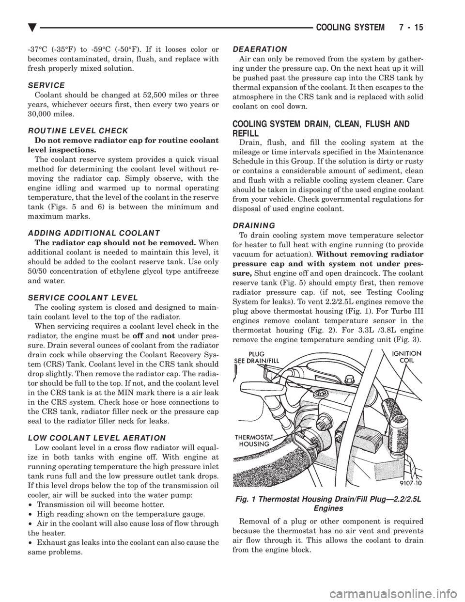
System for leaks). To vent 2.2/2.5L engines remove the
plug above thermostat housing (Fig. 1). For Turbo III
engines remove coolant temperature sensor in the
thermostat housing (Fig. 2). For 3.3L /3.8L engine
remove the engine temperature sending unit (Fig. 3).
Removal of a plug or other component is required
because the thermostat has no air vent and prevents
air flow through it. This allows the coolant to drain
from the engine block.
Fig. 1 Thermostat Housing Drain/Fill PlugÐ2.2/2.5L Engines
Ä COOLING SYSTEM 7 - 15
Page 360 of 2438
RADIATOR PRESSURE CAP
Radiators are equipped with a pressure cap which
releases pressure at some point within a range of
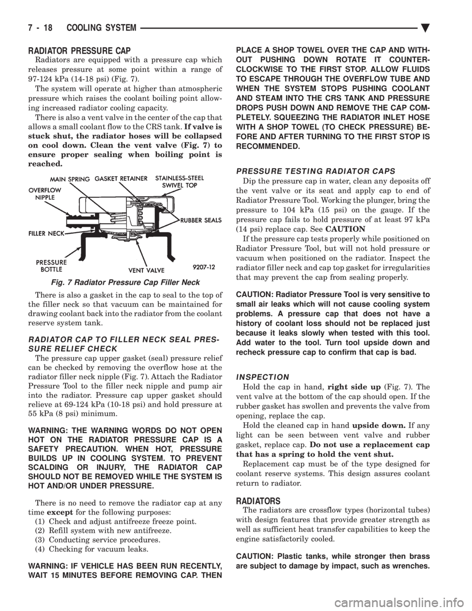
97-124 kPa (14-18 psi) (Fig. 7). The system will operate at higher than atmospheric
pressure which raises the coolant boiling point allow-
ing increased radiator cooling capacity. There is also a vent valve in the center of the cap that
allows a small coolant flow to the CRS tank. If valve is
stuck shut, the radiator hoses will be collapsed
on cool down. Clean the vent valve (Fig. 7) to
ensure proper sealing when boiling point is
reached.
There is also a gasket in the cap to seal to the top of
the filler neck so that vacuum can be maintained for
drawing coolant back into the radiator from the coolant
reserve system tank.
RADIATOR CAP TO FILLER NECK SEAL PRES- SURE RELIEF CHECK
The pressure cap upper gasket (seal) pressure relief
can be checked by removing the overflow hose at the
radiator filler neck nipple (Fig. 7). Attach the Radiator
Pressure Tool to the filler neck nipple and pump air
into the radiator. Pressure cap upper gasket should
relieve at 69-124 kPa (10-18 psi) and hold pressure at
55 kPa (8 psi) minimum.
WARNING: THE WARNING WORDS DO NOT OPEN
HOT ON THE RADIATOR PRESSURE CAP IS A
SAFETY PRECAUTION. WHEN HOT, PRESSURE
BUILDS UP IN COOLING SYSTEM. TO PREVENT
SCALDING OR INJURY, THE RADIATOR CAP
SHOULD NOT BE REMOVED WHILE THE SYSTEM IS
HOT AND/OR UNDER PRESSURE.
There is no need to remove the radiator cap at any
time except for the following purposes:
(1) Check and adjust antifreeze freeze point.
(2) Refill system with new antifreeze.
(3) Conducting service procedures.
(4) Checking for vacuum leaks.
WARNING: IF VEHICLE HAS BEEN RUN RECENTLY,
WAIT 15 MINUTES BEFORE REMOVING CAP. THEN PLACE A SHOP TOWEL OVER THE CAP AND WITH-
OUT PUSHING DOWN ROTATE IT COUNTER-
CLOCKWISE TO THE FIRST STOP. ALLOW FLUIDS
TO ESCAPE THROUGH THE OVERFLOW TUBE AND
WHEN THE SYSTEM STOPS PUSHING COOLANT
AND STEAM INTO THE CRS TANK AND PRESSURE
DROPS PUSH DOWN AND REMOVE THE CAP COM-
PLETELY. SQUEEZING THE RADIATOR INLET HOSE
WITH A SHOP TOWEL (TO CHECK PRESSURE) BE-
FORE AND AFTER TURNING TO THE FIRST STOP IS
RECOMMENDED.
PRESSURE TESTING RADIATOR CAPS
Dip the pressure cap in water, clean any deposits off
the vent valve or its seat and apply cap to end of
Radiator Pressure Tool. Working the plunger, bring the
pressure to 104 kPa (15 psi) on the gauge. If the
pressure cap fails to hold pressure of at least 97 kPa
(14 psi) replace cap. See CAUTION
If the pressure cap tests properly while positioned on
Radiator Pressure Tool, but will not hold pressure or
vacuum when positioned on the radiator. Inspect the
radiator filler neck and cap top gasket for irregularities
that may prevent the cap from sealing properly.
CAUTION: Radiator Pressure Tool is very sensitive to
small air leaks which will not cause cooling system
problems. A pressure cap that does not have a
history of coolant loss should not be replaced just
because it leaks slowly when tested with this tool.
Add water to the tool. Turn tool upside down and
recheck pressure cap to confirm that cap is bad.
INSPECTION
Hold the cap in hand, right side up(Fig. 7). The
vent valve at the bottom of the cap should open. If the
rubber gasket has swollen and prevents the valve from
opening, replace the cap. Hold the cleaned cap in hand upside down.If any
light can be seen between vent valve and rubber
gasket, replace cap. Do not use a replacement cap
that has a spring to hold the vent shut. Replacement cap must be of the type designed for
coolant reserve systems. This design assures coolant
return to radiator.
RADIATORS
The radiators are crossflow types (horizontal tubes)
with design features that provide greater strength as
well as sufficient heat transfer capabilities to keep the
engine satisfactorily cooled.
CAUTION: Plastic tanks, while stronger then brass
are subject to damage by impact, such as wrenches.
Fig. 7 Radiator Pressure Cap Filler Neck
7 - 18 COOLING SYSTEM Ä
Page 365 of 2438
FAN SHROUD
All vehicles have fan shrouds to improve fan air
flow efficiency. These fan shrouds cover less than full
radiator frontal area to prevent the shroud from re-
stricting air flow at high speeds. The shroud supports the electric fan motor and fan.
For removal and installation see Radiator Section.
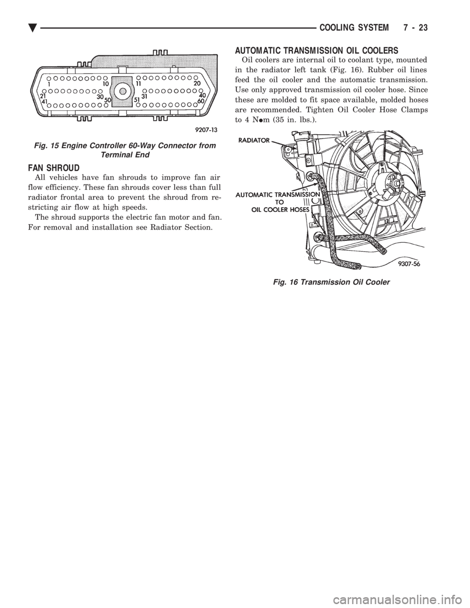
AUTOMATIC TRANSMISSION OIL COOLERS
Oil coolers are internal oil to coolant type, mounted
in the radiator left tank (Fig. 16). Rubber oil lines
feed the oil cooler and the automatic transmission.
Use only approved transmission oil cooler hose. Since
these are molded to fit space available, molded hoses
are recommended. Tighten Oil Cooler Hose Clamps
to4N Im (35 in. lbs.).
Fig. 15 Engine Controller 60-Way Connector from
Terminal End
Fig. 16 Transmission Oil Cooler
Ä COOLING SYSTEM 7 - 23
Page 444 of 2438
Light scaling of the terminals can be cleaned with
a sharp knife. If the terminals are heavily scaled, re-
place the distributor cap. A cap that is greasy, dirty or has a powder-like
substance on the inside should be cleaned with a so-
lution of warm water and a mild detergent. Scrub
the cap with a soft brush. Thoroughly rinse the cap
and dry it with a clean soft cloth.
ROTOR
Replace the rotor if it is cracked, the tip is exces-
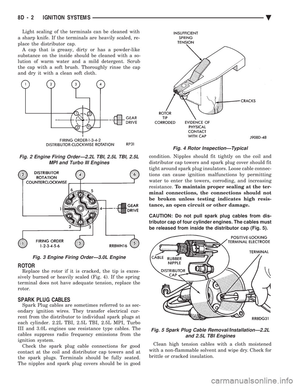
sively burned or heavily scaled (Fig. 4). If the spring
terminal does not have adequate tension, replace the
rotor.
SPARK PLUG CABLES
Spark Plug cables are sometimes referred to as sec-
ondary ignition wires. They transfer electrical cur-
rent from the distributor to individual spark plugs at
each cylinder. 2.2L TBI, 2.5L TBI, 2.5L MPI, Turbo
III and 3.0L engines use resistance type cables. The
cables suppress radio frequency emissions from the
ignition system. Check the spark plug cable connections for good
contact at the coil and distributor cap towers and at
the spark plugs. Terminals should be fully seated.
The nipples and spark plug covers should be in good condition. Nipples should fit tightly on the coil and
distributor cap towers and spark plug cover should fit
tight around spark plug insulators. Loose cable connec-
tions can cause ignition malfunctions by permitting
water to enter the towers, corroding, and increasing
resistance. To maintain proper sealing at the ter-
minal connections, the connections should not
be broken unless testing indicates high resis-
tance, an open circuit or other damage.
CAUTION: Do not pull spark plug cables from dis-
tributor cap of four cylinder engines. The cables must
be released from inside the distributor cap (Fig. 5).
Clean high tension cables with a cloth moistened
with a non-flammable solvent and wipe dry. Check for
brittle or cracked insulation.
Fig. 2 Engine Firing OrderÐ2.2L TBI, 2.5L TBI, 2.5L MPI and Turbo III Engines
Fig. 3 Engine Firing OrderÐ3.0L Engine
Fig. 4 Rotor InspectionÐTypical
Fig. 5 Spark Plug Cable Removal/InstallationÐ2.2L and 2.5L TBI Engines
8D - 2 IGNITION SYSTEMS Ä