CHEVROLET PLYMOUTH ACCLAIM 1993 Service Manual
Manufacturer: CHEVROLET, Model Year: 1993, Model line: PLYMOUTH ACCLAIM, Model: CHEVROLET PLYMOUTH ACCLAIM 1993Pages: 2438, PDF Size: 74.98 MB
Page 2411 of 2438
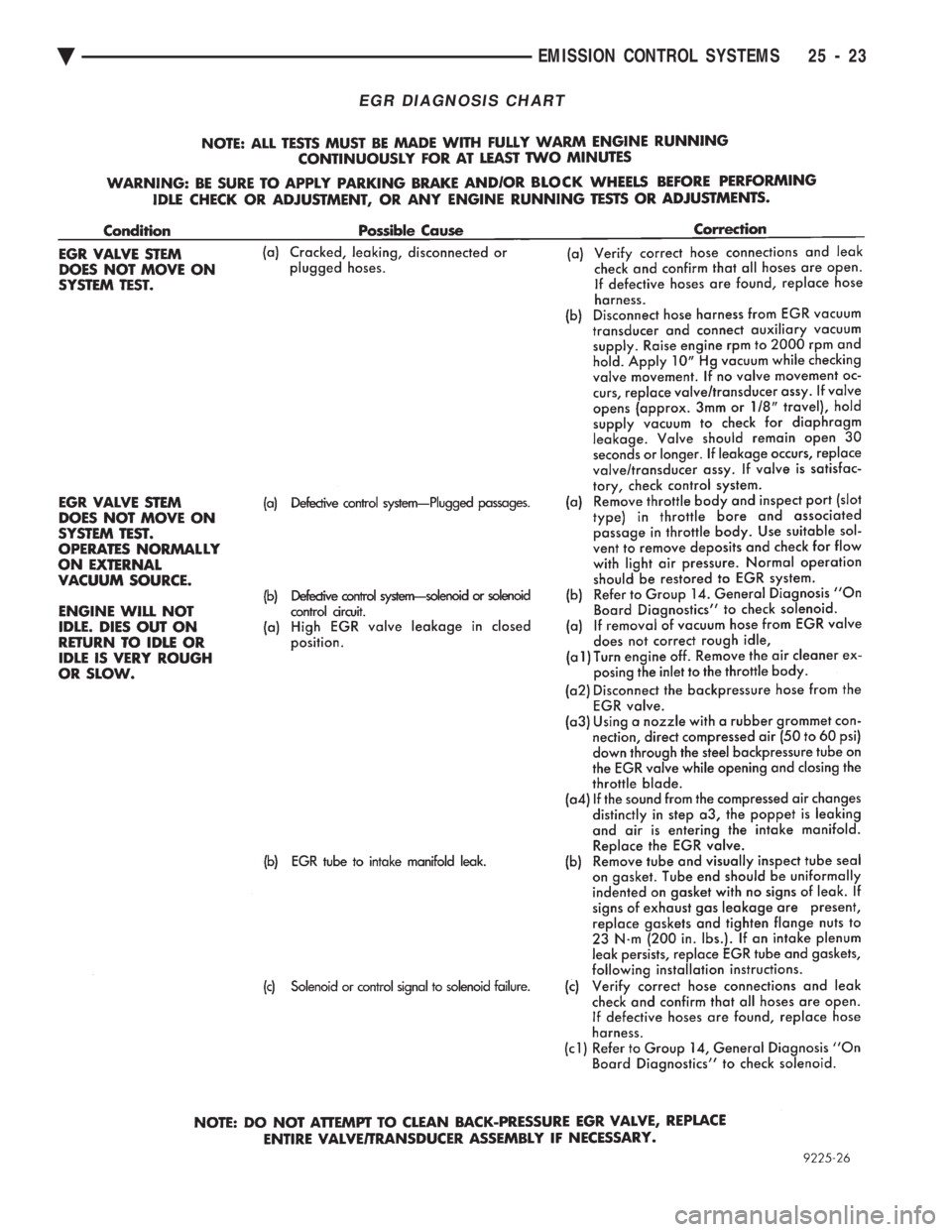
EGR DIAGNOSIS CHART
Ä EMISSION CONTROL SYSTEMS 25 - 23
Page 2412 of 2438
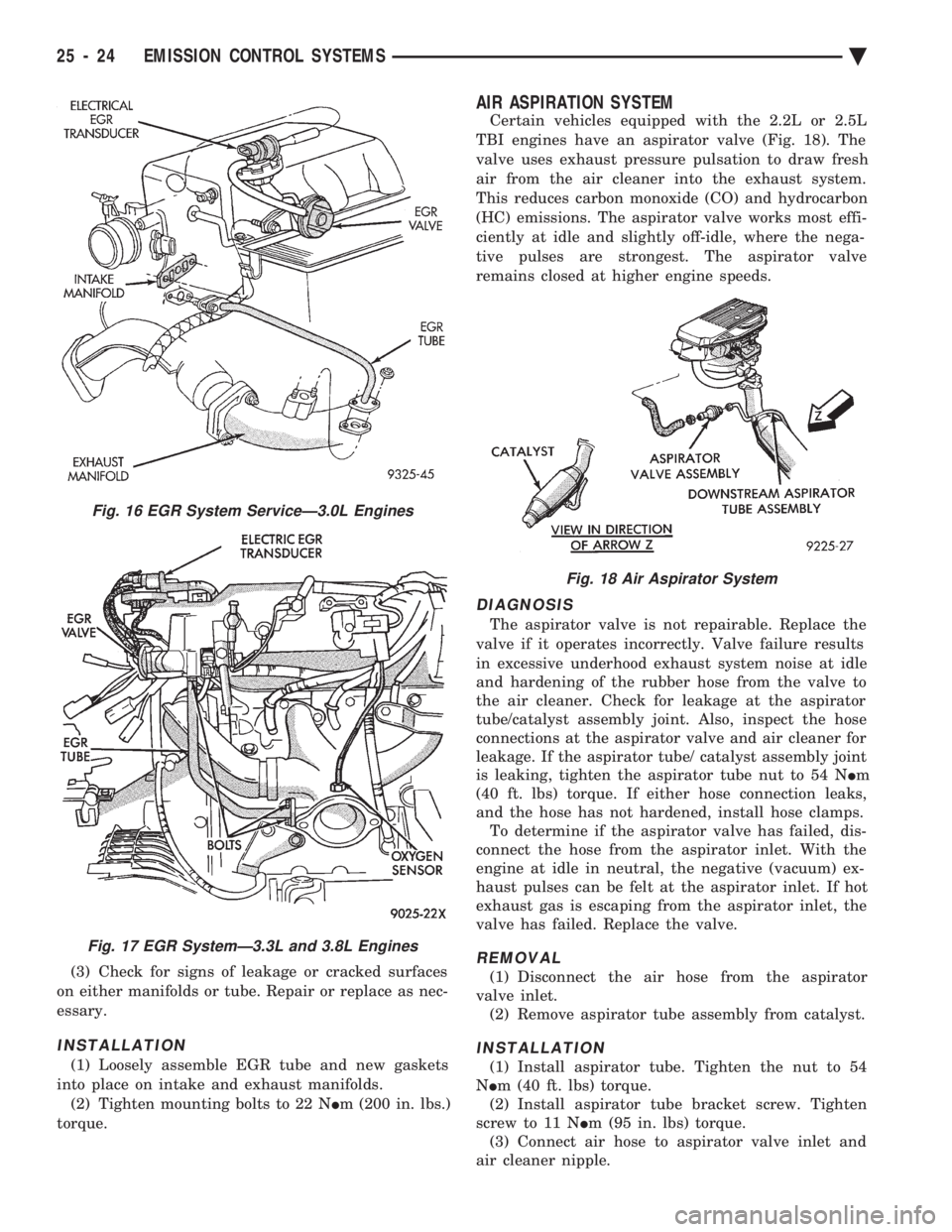
(3) Check for signs of leakage or cracked surfaces
on either manifolds or tube. Repair or replace as nec-
essary.
INSTALLATION
(1) Loosely assemble EGR tube and new gaskets
into place on intake and exhaust manifolds. (2) Tighten mounting bolts to 22 N Im (200 in. lbs.)
torque.
AIR ASPIRATION SYSTEM
Certain vehicles equipped with the 2.2L or 2.5L
TBI engines have an aspirator valve (Fig. 18). The
valve uses exhaust pressure pulsation to draw fresh
air from the air cleaner into the exhaust system.
This reduces carbon monoxide (CO) and hydrocarbon
(HC) emissions. The aspirator valve works most effi-
ciently at idle and slightly off-idle, where the nega-
tive pulses are strongest. The aspirator valve
remains closed at higher engine speeds.
DIAGNOSIS
The aspirator valve is not repairable. Replace the
valve if it operates incorrectly. Valve failure results
in excessive underhood exhaust system noise at idle
and hardening of the rubber hose from the valve to
the air cleaner. Check for leakage at the aspirator
tube/catalyst assembly joint. Also, inspect the hose
connections at the aspirator valve and air cleaner for
leakage. If the aspirator tube/ catalyst assembly joint
is leaking, tighten the aspirator tube nut to 54 N Im
(40 ft. lbs) torque. If either hose connection leaks,
and the hose has not hardened, install hose clamps. To determine if the aspirator valve has failed, dis-
connect the hose from the aspirator inlet. With the
engine at idle in neutral, the negative (vacuum) ex-
haust pulses can be felt at the aspirator inlet. If hot
exhaust gas is escaping from the aspirator inlet, the
valve has failed. Replace the valve.
REMOVAL
(1) Disconnect the air hose from the aspirator
valve inlet. (2) Remove aspirator tube assembly from catalyst.
INSTALLATION
(1) Install aspirator tube. Tighten the nut to 54
N Im (40 ft. lbs) torque.
(2) Install aspirator tube bracket screw. Tighten
screw to 11 N Im (95 in. lbs) torque.
(3) Connect air hose to aspirator valve inlet and
air cleaner nipple.
Fig. 16 EGR System ServiceÐ3.0L Engines
Fig. 17 EGR SystemÐ3.3L and 3.8L Engines
Fig. 18 Air Aspirator System
25 - 24 EMISSION CONTROL SYSTEMS Ä
Page 2413 of 2438
CHRYSLER
CORPORATION
SERVICE MANUAL and SUPPLEMENTS
1993 FRONT WHEEL DRIVE PASSENGER VEHICLES
To order the special service tools used and
illustrated, please refer to the instructions on
inside back cover.
NO PART OF THIS PUBLICATION MAY BE
REPRODUCED, STORED IN A RETRIEVAL
SYSTEM, OR TRANSMITTED, IN ANY FORM
OR BY ANY MEANS, ELECTRONIC, ME-
CHANICAL, PHOTOCOPYING, RECORDING,
OR OTHERWISE, WITHOUT THE PRIOR
WRITTEN PERMISSION OF CHRYSLER
CORPORATION.
Chrysler Corporation reserves the right to make changes in design or to make
additions to or improvements in its products without imposing any obligations
upon itself to install them on its products previously manufactured.
Litho in U.S.A. Copyright 1992 Chrysler Corporation 30M0792
NEXT PAGE ©
Page 2414 of 2438
FOREWORD
The information contained in this Service Manual has been prepared for the professional automotive
technician involved in daily repair operations. Information describing the operation and use of standard and
optional equipment is included in the Owner's Manual provided with the vehicle.
These diagrams contain the latest information at the time of publication and incorporate the wiring schematic
for the basic vehicle and available optional equipment.
The diagrams are grouped by body type and sales division. The body codes are explained in the General
Information section. (ExampleÐAP-D, P=Shadow, Sundance). To locate a system or component refer to the black
index tabs on the next page. The tab will assist you in locating the desired area of the manual.
An alphabetical index is provided at the beginning of each section to help you in locating a system or
component. All diagrams are identified by SHEET NUMBER which is found in the lower right- or left-hand corner
of the page.
A Service Manual Comment form is included at the rear of this manual. Use the form to provide Chrysler
Corporation with your comments and suggestions.
Chrysler Corporation reserves the right to change testing procedures, specifications, diagnosis, repair
methods, or vehicle wiring at any time without prior notice or incurring obligation.
NOTE: The acronyms, terminology and nomenclature used to identify emissions related components in this
manual may have changed from prior publications. These new terms are in compliance with S.A.E.
recommended practice J1930. This terminology standard (J1930) is required to comply with the 1993
California Air Research Board (CARB) requirements.
NEXT PAGE ©
Page 2415 of 2438
GROUP TAB LOCATOR
ENGINE, CHASSIS BODY
ELECTRICAL, FUEL EMISSION SYSTEMS
WIRING DIAGRAMS
SUPPLEMENTS
Service Manual Comment Forms (Rear of Manual)
Page 2416 of 2438
INTRODUCTION
CONTENTS
page page
BODY CODE PLATE LOCATION AND DECODING INFORMATION ........................ 2
INTERNATIONAL SYMBOLS ................ 9
METRIC SYSTEM ........................ 6
METRIC THREAD AND GRADE IDENTIFICATION ....................... 6 TORQUE REFERENCES
.................... 6
VEHICLE FAMILY IDENTIFICATION ........... 1
VEHICLE IDENTIFICATION NUMBER ......... 1
VEHICLE SAFETY CERTIFICATION LABEL ..... 1
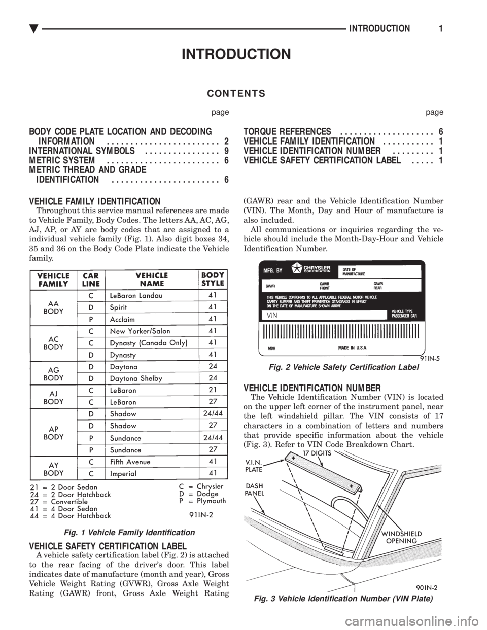
VEHICLE FAMILY IDENTIFICATION
Throughout this service manual references are made
to Vehicle Family, Body Codes. The letters AA, AC, AG,
AJ, AP, or AY are body codes that are assigned to a
individual vehicle family (Fig. 1). Also digit boxes 34,
35 and 36 on the Body Code Plate indicate the Vehicle
family.
VEHICLE SAFETY CERTIFICATION LABEL
A vehicle safety certification label (Fig. 2) is attached
to the rear facing of the driver's door. This label
indicates date of manufacture (month and year), Gross
Vehicle Weight Rating (GVWR), Gross Axle Weight
Rating (GAWR) front, Gross Axle Weight Rating (GAWR) rear and the Vehicle Identification Number
(VIN). The Month, Day and Hour of manufacture is
also included. All communications or inquiries regarding the ve-
hicle should include the Month-Day-Hour and Vehicle
Identification Number.
VEHICLE IDENTIFICATION NUMBER
The Vehicle Identification Number (VIN) is located
on the upper left corner of the instrument panel, near
the left windshield pillar. The VIN consists of 17
characters in a combination of letters and numbers
that provide specific information about the vehicle
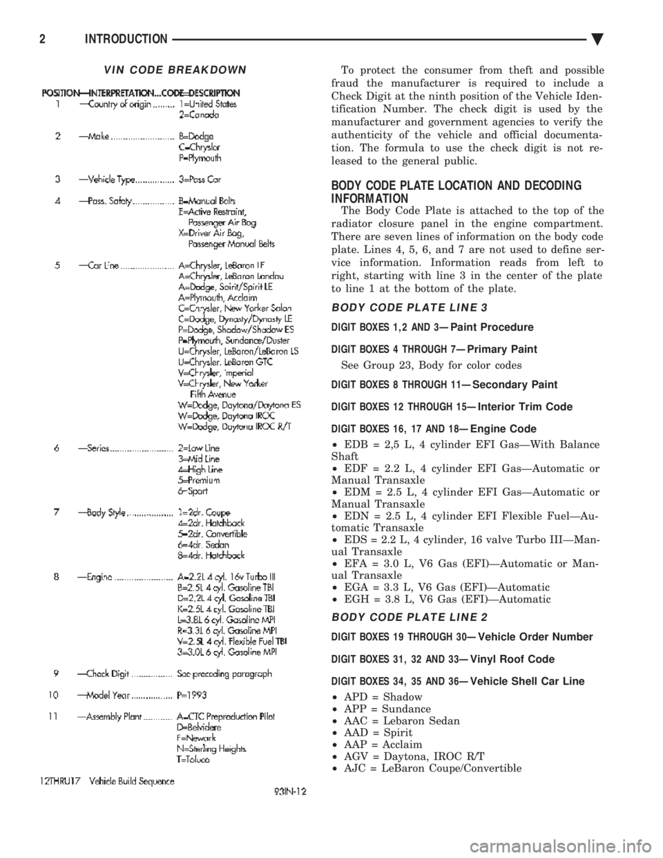
(Fig. 3). Refer to VIN Code Breakdown Chart.
Fig. 3 Vehicle Identification Number (VIN Plate)
Fig. 1 Vehicle Family Identification
Fig. 2 Vehicle Safety Certification Label
Ä INTRODUCTION1
Page 2417 of 2438
To protect the consumer from theft and possible
fraud the manufacturer is required to include a
Check Digit at the ninth position of the Vehicle Iden-
tification Number. The check digit is used by the
manufacturer and government agencies to verify the
authenticity of the vehicle and official documenta-
tion. The formula to use the check digit is not re-
leased to the general public.
BODY CODE PLATE LOCATION AND DECODING
INFORMATION
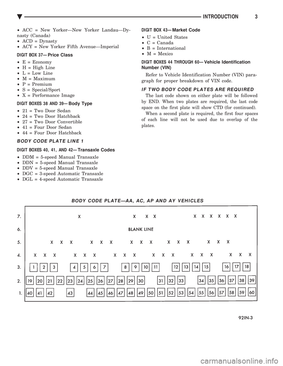
The Body Code Plate is attached to the top of the
radiator closure panel in the engine compartment.
There are seven lines of information on the body code
plate. Lines 4, 5, 6, and 7 are not used to define ser-
vice information. Information reads from left to
right, starting with line 3 in the center of the plate
to line 1 at the bottom of the plate.
BODY CODE PLATE LINE 3
DIGIT BOXES 1,2 AND 3Ð Paint Procedure
DIGIT BOXES 4 THROUGH 7Ð Primary Paint
See Group 23, Body for color codes
DIGIT BOXES 8 THROUGH 11Ð Secondary Paint
DIGIT BOXES 12 THROUGH 15Ð Interior Trim Code
DIGIT BOXES 16, 17 AND 18Ð Engine Code
² EDB = 2,5 L, 4 cylinder EFI GasÐWith Balance
Shaft
² EDF = 2.2 L, 4 cylinder EFI GasÐAutomatic or
Manual Transaxle
² EDM = 2.5 L, 4 cylinder EFI GasÐAutomatic or
Manual Transaxle
² EDN = 2.5 L, 4 cylinder EFI Flexible FuelÐAu-
tomatic Transaxle
² EDS = 2.2 L, 4 cylinder, 16 valve Turbo IIIÐMan-
ual Transaxle
² EFA = 3.0 L, V6 Gas (EFI)ÐAutomatic or Man-
ual Transaxle
² EGA = 3.3 L, V6 Gas (EFI)ÐAutomatic
² EGH = 3.8 L, V6 Gas (EFI)ÐAutomatic
BODY CODE PLATE LINE 2
DIGIT BOXES 19 THROUGH 30Ð Vehicle Order Number
DIGIT BOXES 31, 32 AND 33Ð Vinyl Roof Code
DIGIT BOXES 34, 35 AND 36Ð Vehicle Shell Car Line
² APD = Shadow
² APP = Sundance
² AAC = Lebaron Sedan
² AAD = Spirit
² AAP = Acclaim
² AGV = Daytona, IROC R/T
² AJC = LeBaron Coupe/Convertible
VIN CODE BREAKDOWN
2 INTRODUCTION Ä
Page 2418 of 2438
² ACC = New YorkerÐNew Yorker LandauÐDy-
nasty (Canada)
² ACD = Dynasty
² ACY = New Yorker Fifth AvenueÐImperial
DIGIT BOX 37Ð Price Class
² E = Economy
² H = High Line
² L = Low Line
² M = Maximum
² P = Premium
² S = Special/Sport
² X = Performance Image
DIGIT BOXES 38 AND 39Ð Body Type
² 21 = Two Door Sedan
² 24 = Two Door Hatchback
² 27 = Two Door Convertible
² 41 = Four Door Sedan
² 44 = Four Door Hatchback
BODY CODE PLATE LINE 1
DIGIT BOXES 40, 41, AND 42Ð Transaxle Codes
² DDM = 5-speed Manual Transaxle
² DDN = 5-speed Manual Transaxle
² DDV = 5-speed Manual Transaxle
² DGC = 3-speed Automatic Transaxle
² DGL = 4-speed Automatic Transaxle DIGIT BOX 43Ð
Market Code
² U = United States
² C = Canada
² B = International
² M = Mexico
DIGIT BOXES 44 THROUGH 60Ð Vehicle Identification
Number (VIN)
Refer to Vehicle Identification Number (VIN) para-
graph for proper breakdown of VIN code.
IF TWO BODY CODE PLATES ARE REQUIRED
The last code shown on either plate will be followed
by END. When two plates are required, the last code
space on the first plate will show CTD (for continued). When a second plate is required, the first four spaces
of each line will not be used due to overlap of the
plates.
BODY CODE PLATEÐAA, AC, AP AND AY VEHICLES
Ä INTRODUCTION3
Page 2419 of 2438
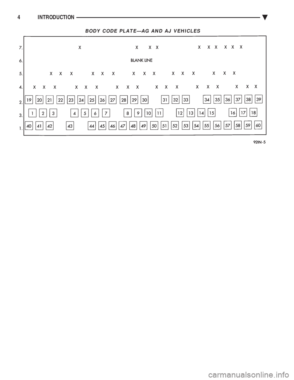
BODY CODE PLATEÐAG AND AJ VEHICLES
4 INTRODUCTION Ä
Page 2420 of 2438
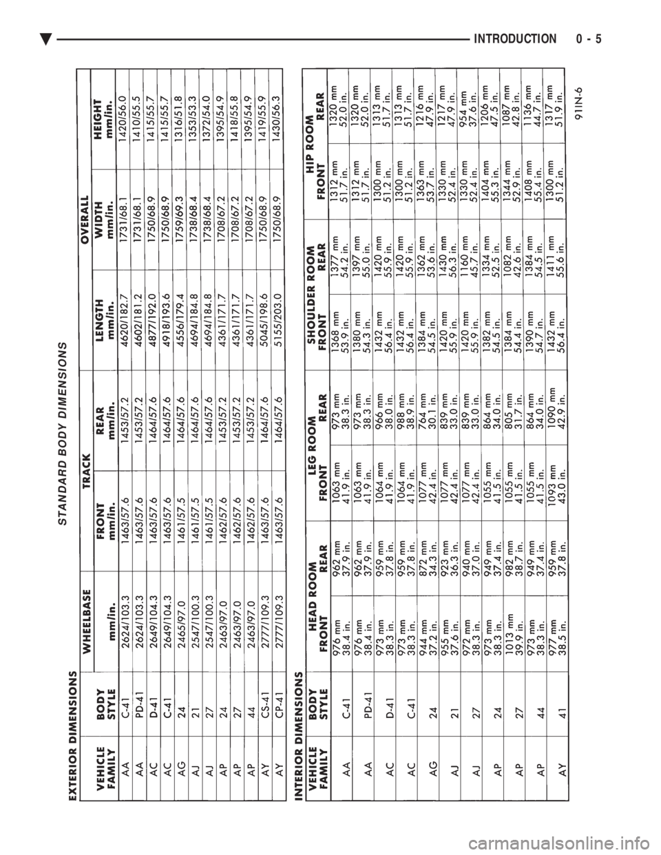
STANDARD BODY DIMENSIONS
Ä INTRODUCTION 0 - 5