key CHEVROLET PLYMOUTH ACCLAIM 1993 Workshop Manual
[x] Cancel search | Manufacturer: CHEVROLET, Model Year: 1993, Model line: PLYMOUTH ACCLAIM, Model: CHEVROLET PLYMOUTH ACCLAIM 1993Pages: 2438, PDF Size: 74.98 MB
Page 533 of 2438
(4) Remove panel top cover by pushing forward
and prying up, using a straight edge to assist in the
removal. (5) Disconnect bulkhead connector at brace under
instrument panel at left side. (6) Remove glovebox/ash receiver module and right
instrument panel silencer. (7) Remove center panel support brace and air bag
diagnostic module assembly. (8) Disconnect wiring to airbag module.
(9) Remove upper and lower cluster bezels.
(10) Remove steering column cover.
(11) Remove steering column mounting nuts and
lower steering column. (12) Unhook shift indicator cable eyelet from steer-
ing column actuator. (13) Unlatch lock tab in shift indicator column in-
sert and squeeze legs together to remove from steer-
ing column. (14) Remove cluster assembly while guiding trans-
mission range indicator guide tube through access
hole in the base panel. (15) Remove instrument panel steering column
opening support/hood release handle assembly. (16) Remove two steering column upper studs and
loosen side cowl tie-down bolts. (17) Remove steering column tilt lever.
(18) Remove upper and lower lock housing shroud.
(19) Remove lower fixed shroud.
(20) Remove upper fixed shroud (snaps in place).
(21) Disconnect airbag pigtail, ignition switch and
halo light/key buzzer switch wiring. (22) Disconnect Multi-function switch by loosening
connector jack screw and pulling connector from
switch. (23) Disconnect airbag pigtail from wiring trough
housing by pulling two push fasteners. (24) Remove wiring trough from steering column.
(25) Remove defroster ducts.
(26) Remove five screws along fence line and roll
panel down, attach a hook to hold in position. (27) Open hood and remove plenum grill.
(28) Disconnect washer bottle, resistor block and
under hood lamp wiring. Washer bottle must be re-
moved to gain access. (29) Remove grommet and pull plenum wiring into
vehicle through plenum panel. (30) Disconnect right demister hose from instru-
ment panel. (31) Disconnect antenna cable.
(32) Disconnect right and left 25 way body wiring
connectors. (33) Disconnect A/C heater control cables, wiring
connectors and vacuum harness. (34) Remove right side panel ground wire.
(35) Disconnect body controller wiring.
(36) Remove instrument panel assembly from vehi-
cle. (37) For installation reverse above procedures.
INTERIOR LAMP REPLACEMENT
The reading, overhead console and door lamps op-
erate when the doors are open or headlamp switch is
placed in courtesy position. Front overhead lamps re-
fer to Group 8C, Overhead Console.
TRUNK LAMP
The lamp has easily accessible without removing
components.
DOOR LAMP
Pry along the forward edge of the lens and pivot
lens out of the door trim panel. Remove lamp. To re-
move lamp housing, remove door trim panel. Refer to
Group 23, Body. Disconnect all wiring. Remove
screws, if so equipped securing lamp housing to trim
panel, and replace housing.
CÐPILLAR READING/COURTESY LAMP
Pry along the rearward edge of the lamp and pivot
lamp out from quarter trim panel. Disconnect wiring
and remove lamp cover. Replace lamp. The lamp operates when the doors are open or the
headlamp switch is turned to the courtesy mode. The
lamp will function as a reading lamp when the doors
are closed and the button switch on the lamp is de-
pressed.
ROOF RAIL READING
Pry along the bottom edge of the lens and pivot
lens out. Replace lamp. To remove the lamp, remove
the screw which retains the coat hook. Remove the
garnish molding. Disconnect the wiring harness. Re-
move the two clips which retain the lamp to the
molding. Replace lamp. The lamp operates like the
C-pillar reading/courtesy lamp.
Ä INSTRUMENT PANEL AND GAUGES 8E - 41
Page 536 of 2438
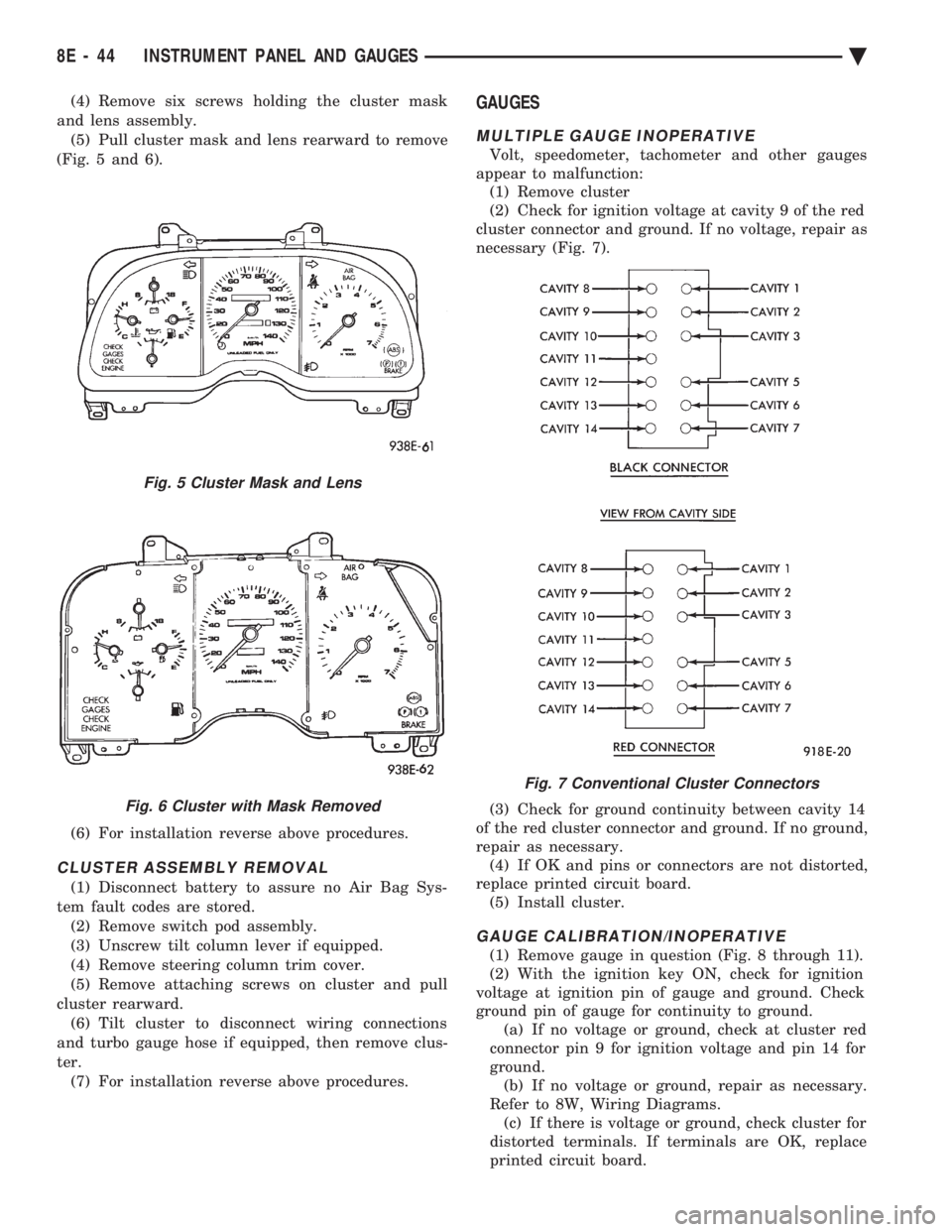
(4) Remove six screws holding the cluster mask
and lens assembly. (5) Pull cluster mask and lens rearward to remove
(Fig. 5 and 6).
(6) For installation reverse above procedures.
CLUSTER ASSEMBLY REMOVAL
(1) Disconnect battery to assure no Air Bag Sys-
tem fault codes are stored. (2) Remove switch pod assembly.
(3) Unscrew tilt column lever if equipped.
(4) Remove steering column trim cover.
(5) Remove attaching screws on cluster and pull
cluster rearward. (6) Tilt cluster to disconnect wiring connections
and turbo gauge hose if equipped, then remove clus-
ter. (7) For installation reverse above procedures.
GAUGES
MULTIPLE GAUGE INOPERATIVE
Volt, speedometer, tachometer and other gauges
appear to malfunction: (1) Remove cluster
(2) Check for ignition voltage at cavity 9 of the red
cluster connector and ground. If no voltage, repair as
necessary (Fig. 7).
(3) Check for ground continuity between cavity 14
of the red cluster connector and ground. If no ground,
repair as necessary. (4) If OK and pins or connectors are not distorted,
replace printed circuit board. (5) Install cluster.
GAUGE CALIBRATION/INOPERATIVE
(1) Remove gauge in question (Fig. 8 through 11).
(2) With the ignition key ON, check for ignition
voltage at ignition pin of gauge and ground. Check
ground pin of gauge for continuity to ground. (a) If no voltage or ground, check at cluster red
connector pin 9 for ignition voltage and pin 14 for
ground. (b) If no voltage or ground, repair as necessary.
Refer to 8W, Wiring Diagrams. (c) If there is voltage or ground, check cluster for
distorted terminals. If terminals are OK, replace
printed circuit board.
Fig. 5 Cluster Mask and Lens
Fig. 6 Cluster with Mask Removed
Fig. 7 Conventional Cluster Connectors
8E - 44 INSTRUMENT PANEL AND GAUGES Ä
Page 539 of 2438
(3) With the ignition switch ON, an open (discon-
nected sending unit wire) causes the oil, fuel or tem-
perature gauge to read below low, empty or cold
indicators. (4) If steps 2 and 3 check OK, refer to the individ-
ual sending unit test procedures.
FUEL TANK SENDING UNIT TEST
Refer to Group 14, Fuel for test procedure.
CHECK GAUGES WARNING LAMP TESTS
The check gauges warning lamp will illuminated
when the ignition key is turned to the ON position.
The lamp will illuminate if the engine oil pressure
drops below a safe level. The check gauge lamp will
light for high engine temperature or for low voltage. To test the system turn ignition key to the ON po-
sition. If the lamp fails to light, inspect for a broken
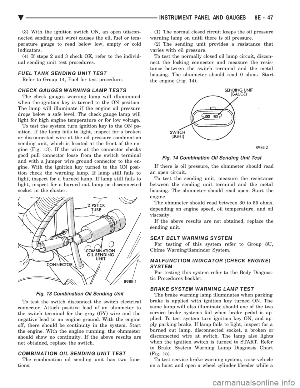
or disconnected wire at the oil pressure combination
sending unit, which is located at the front of the en-
gine (Fig. 13). If the wire at the connector checks
good pull connector loose from the switch terminal
and with a jumper wire ground connector to the en-
gine. With the ignition key turned to the ON posi-
tion check the warning lamp. If lamp still fails to
light, inspect for a burned lamp. If lamp still fails to
light, inspect for a burned out lamp or disconnected
socket in the cluster.
To test the switch disconnect the switch electrical
connector. Attach positive lead of an ohmmeter to
the switch terminal for the gray (GY) wire and the
negative lead to an engine ground. With the engine
off, there should be continuity in the system. Start
the engine. With the engine running, the ohmmeter
should show no continuity. If the above results are
not obtained, replace the switch.
COMBINATION OIL SENDING UNIT TEST
The combination oil sending unit has two func-
tions: (1) The normal closed circuit keeps the oil pressure
warning lamp on until there is oil pressure. (2) The sending unit provides a resistance that
varies with oil pressure. To test the normally closed oil lamp circuit, discon-
nect the locking connector and measure the resis-
tance between the switch terminal and the metal
housing. The ohmmeter should read 0 ohms. Start
the engine (Fig. 14).
If there is oil pressure, the ohmmeter should read
an open circuit. To test the sending unit, measure the resistance
between the sending unit terminal and the metal
housing. The ohmmeter should read open. Start the
engine. The ohmmeter should read between 30 to 55 ohms,
depending on engine speed, oil temperature, and oil
viscosity. If the above results are not obtained, replace the
sending unit.
SEAT BELT WARNING SYSTEM
For testing of this system refer to Group 8U,
Chime Warning/Reminder System.
MALFUNCTION INDICATOR (CHECK ENGINE) SYSTEM
For testing this system refer to the Body Diagnos-
tic Procedures booklet.
BRAKE SYSTEM WARNING LAMP TEST
The brake warning lamp illuminates when parking
brake is applied with ignition key turned ON. The
same lamp will also illuminate should one of the two
service brake systems fail when brake pedal is ap-
plied. To test system turn ignition key ON, and ap-
ply parking brake. If lamp fails to light, inspect for a
burned out lamp, disconnected socket, a broken or
disconnected wire at switch. The lamp also lights
when the ignition switch is turned to START. Refer
to Brake System Warning Lamp Diagnosis Chart
(Fig. 15). To test service brake warning system, raise vehicle
on a hoist and open a wheel cylinder bleeder while aFig. 13 Combination Oil Sending Unit
Fig. 14 Combination Oil Sending Unit Test
Ä INSTRUMENT PANEL AND GAUGES 8E - 47
Page 551 of 2438
FUEL TANK SENDING UNIT TEST
Refer to Group 14, Fuel for test procedures.
LOW OIL PRESSURE WARNING LAMP TEST
The low oil pressure warning lamp will illuminate
when the ignition key is turned to the ON position
without engine running. The lamp also illuminates
should the engine oil pressure drop below a safe oil
pressure level. To test the system turn ignition key to the ON po-
sition. If the lamp fails to light, inspect for a broken
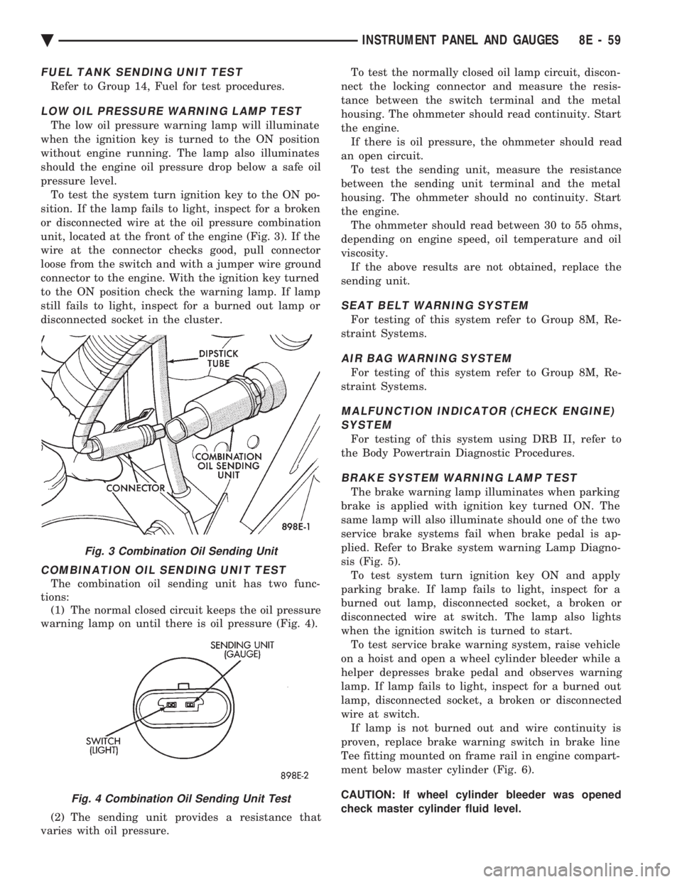
or disconnected wire at the oil pressure combination
unit, located at the front of the engine (Fig. 3). If the
wire at the connector checks good, pull connector
loose from the switch and with a jumper wire ground
connector to the engine. With the ignition key turned
to the ON position check the warning lamp. If lamp
still fails to light, inspect for a burned out lamp or
disconnected socket in the cluster.
COMBINATION OIL SENDING UNIT TEST
The combination oil sending unit has two func-
tions: (1) The normal closed circuit keeps the oil pressure
warning lamp on until there is oil pressure (Fig. 4).
(2) The sending unit provides a resistance that
varies with oil pressure. To test the normally closed oil lamp circuit, discon-
nect the locking connector and measure the resis-
tance between the switch terminal and the metal
housing. The ohmmeter should read continuity. Start
the engine. If there is oil pressure, the ohmmeter should read
an open circuit. To test the sending unit, measure the resistance
between the sending unit terminal and the metal
housing. The ohmmeter should no continuity. Start
the engine. The ohmmeter should read between 30 to 55 ohms,
depending on engine speed, oil temperature and oil
viscosity. If the above results are not obtained, replace the
sending unit.
SEAT BELT WARNING SYSTEM
For testing of this system refer to Group 8M, Re-
straint Systems.
AIR BAG WARNING SYSTEM
For testing of this system refer to Group 8M, Re-
straint Systems.
MALFUNCTION INDICATOR (CHECK ENGINE) SYSTEM
For testing of this system using DRB II, refer to
the Body Powertrain Diagnostic Procedures.
BRAKE SYSTEM WARNING LAMP TEST
The brake warning lamp illuminates when parking
brake is applied with ignition key turned ON. The
same lamp will also illuminate should one of the two
service brake systems fail when brake pedal is ap-
plied. Refer to Brake system warning Lamp Diagno-
sis (Fig. 5). To test system turn ignition key ON and apply
parking brake. If lamp fails to light, inspect for a
burned out lamp, disconnected socket, a broken or
disconnected wire at switch. The lamp also lights
when the ignition switch is turned to start. To test service brake warning system, raise vehicle
on a hoist and open a wheel cylinder bleeder while a
helper depresses brake pedal and observes warning
lamp. If lamp fails to light, inspect for a burned out
lamp, disconnected socket, a broken or disconnected
wire at switch. If lamp is not burned out and wire continuity is
proven, replace brake warning switch in brake line
Tee fitting mounted on frame rail in engine compart-
ment below master cylinder (Fig. 6).
CAUTION: If wheel cylinder bleeder was opened
check master cylinder fluid level.
Fig. 3 Combination Oil Sending Unit
Fig. 4 Combination Oil Sending Unit Test
Ä INSTRUMENT PANEL AND GAUGES 8E - 59
Page 553 of 2438
(5) Reconnect battery.
GAUGES
CAUTION: During the removal and installation
watch overlays are not damage.
It is not necessary to remove instrument cluster
from vehicle for gauge replacement. When removing gauge assemblies from cluster,
gauge must be pulled straight out, not twisted, or
damage to gauge pins may result.
MULTIPLE GAUGE INOPERATIVE
Volt, speedometer, tachometer and other gauges
appear to malfunction. Also check warning indicator
lamps: (1) Remove cluster
(2) Check for ignition voltage at pin E of the red
connector. If no voltage, repair as necessary (Fig. 8). (3) Check for ground continuity between pin C of
the gray connector. If no ground, repair as necessary. (4) If voltage and ground OK and pins or connec-
tors are not distorted, replace printed circuit board. (5) Install cluster.
SINGLE GAUGE INOPERATIVE (FIG. 9 AND10)
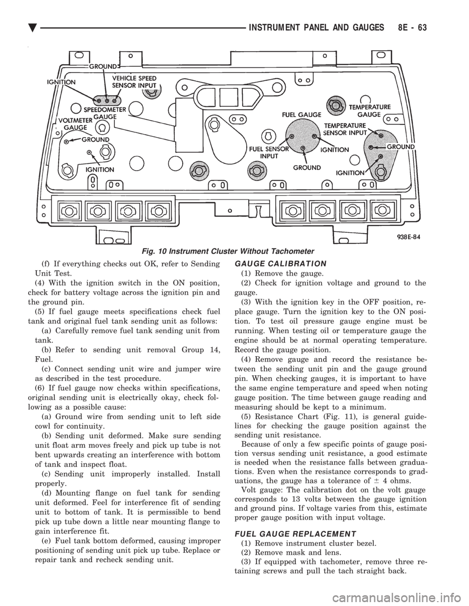
(1) Remove gauge in question. (2) With the ignition key ON, check for ignition
voltage at ignition pin of gauge. Check for ground at
ground pin of gauge. (a) If no voltage or ground, remove cluster and
check pin E red connector for ignition voltage or
pin C gray connector for ground (Fig. 8). (b) If no voltage or ground, repair as necessary.
Refer to 8W, Wiring Diagrams. (c) If there is voltage or ground, check cluster for
distorted terminals. If terminals are OK, replace
printed circuit board.
(3) When testing the temperature gauge, allow the
engine to run until the vehicle reaches a normal op-
erating temperature. Turn ignition OFF and remove
gauge from cluster.
² When checking the temperature and oil pressure
gauges, it is important to have the same engine tem-
perature and engine speed when noting gauge posi-
tion.
² The time between gauge position reading and
sending unit measuring should be kept to a mini-
mum.
² When testing oil pressure gauge, engine needs to
be running. (a) Measure and record the resistance between
sending unit pin and ground pin of the gauge in
question. Refer to Gauge Calibration.
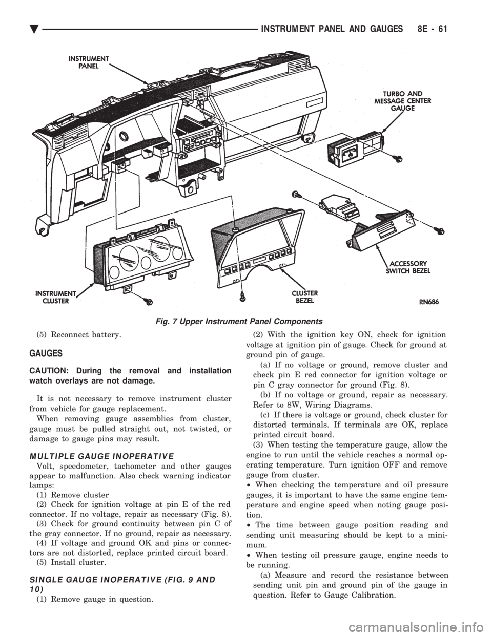
Fig. 7 Upper Instrument Panel Components
Ä INSTRUMENT PANEL AND GAUGES 8E - 61
Page 555 of 2438
(f) If everything checks out OK, refer to Sending
Unit Test.
(4) With the ignition switch in the ON position,
check for battery voltage across the ignition pin and
the ground pin. (5) If fuel gauge meets specifications check fuel
tank and original fuel tank sending unit as follows: (a) Carefully remove fuel tank sending unit from
tank. (b) Refer to sending unit removal Group 14,
Fuel. (c) Connect sending unit wire and jumper wire
as described in the test procedure.
(6) If fuel gauge now checks within specifications,
original sending unit is electrically okay, check fol-
lowing as a possible cause: (a) Ground wire from sending unit to left side
cowl for continuity. (b) Sending unit deformed. Make sure sending
unit float arm moves freely and pick up tube is not
bent upwards creating an interference with bottom
of tank and inspect float. (c) Sending unit improperly installed. Install
properly. (d) Mounting flange on fuel tank for sending
unit deformed. Feel for interference fit of sending
unit to bottom of tank. It is permissible to bend
pick up tube down a little near mounting flange to
gain interference fit. (e) Fuel tank bottom deformed, causing improper
positioning of sending unit pick up tube. Replace or
repair tank and recheck sending unit.GAUGE CALIBRATION
(1) Remove the gauge.
(2) Check for ignition voltage and ground to the
gauge. (3) With the ignition key in the OFF position, re-
place gauge. Turn the ignition key to the ON posi-
tion. To test oil pressure gauge engine must be
running. When testing oil or temperature gauge the
engine should be at normal operating temperature.
Record the gauge position. (4) Remove gauge and record the resistance be-
tween the sending unit pin and the gauge ground
pin. When checking gauges, it is important to have
the same engine temperature and speed when noting
gauge position. The time between gauge reading and
measuring should be kept to a minimum. (5) Resistance Chart (Fig. 11), is general guide-
lines for checking the gauge position against the
sending unit resistance. Because of only a few specific points of gauge posi-
tion versus sending unit resistance, a good estimate
is needed when the resistance falls between gradua-
tions. Even when the resistance corresponds to grad-
uations, the gauge has a tolerance of 64 ohms.
Volt gauge: The calibration dot on the volt gauge
corresponds to 13 volts between the gauge ignition
and ground pins. If voltage varies from this, estimate
proper gauge position with input voltage.
FUEL GAUGE REPLACEMENT
(1) Remove instrument cluster bezel.
(2) Remove mask and lens.
(3) If equipped with tachometer, remove three re-
taining screws and pull the tach straight back.
Fig. 10 Instrument Cluster Without Tachometer
Ä INSTRUMENT PANEL AND GAUGES 8E - 63
Page 589 of 2438
(8) Upon establishing that the fault is in the an-
tenna assembly, it may be traced to one or more of
the following conditions: (a) Broken lead-in wire or shielding.
(b) Grounded lead-in wire or mast assembly.
(c) Moisture in support tube or lead-in assembly.
(d) Poor connection at antenna lead-in assembly
or shielding ground.
REMOVAL
(1) Disconnect battery negative cable.
(2) Remove the right front fender splash shield fas-
teners and pull shield away from the wheel housing.
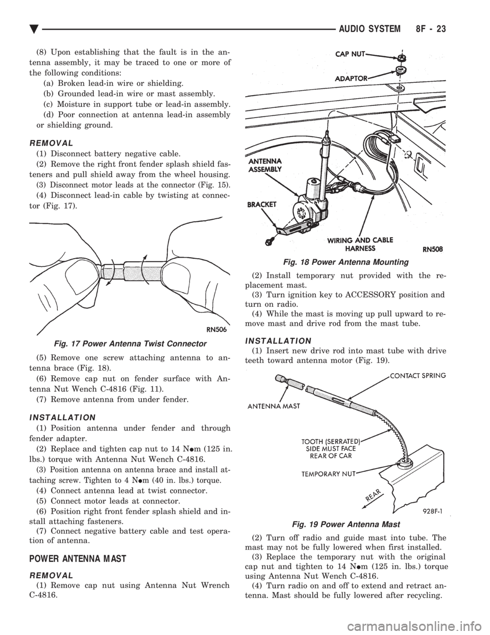
(3) Disconnect motor leads at the connector (Fig. 15).
(4) Disconnect lead-in cable by twisting at connec-
tor (Fig. 17).
(5) Remove one screw attaching antenna to an-
tenna brace (Fig. 18). (6) Remove cap nut on fender surface with An-
tenna Nut Wench C-4816 (Fig. 11). (7) Remove antenna from under fender.
INSTALLATION
(1) Position antenna under fender and through
fender adapter. (2) Replace and tighten cap nut to 14 N Im (125 in.
lbs.) torque with Antenna Nut Wench C-4816.
(3) Position antenna on antenna brace and install at-
taching screw. Tighten to 4 N Im (40 in. lbs.) torque.
(4) Connect antenna lead at twist connector.
(5) Connect motor leads at connector.
(6) Position right front fender splash shield and in-
stall attaching fasteners. (7) Connect negative battery cable and test opera-
tion of antenna.
POWER ANTENNA MAST
REMOVAL
(1) Remove cap nut using Antenna Nut Wrench
C-4816. (2) Install temporary nut provided with the re-
placement mast. (3) Turn ignition key to ACCESSORY position and
turn on radio. (4) While the mast is moving up pull upward to re-
move mast and drive rod from the mast tube.
INSTALLATION
(1) Insert new drive rod into mast tube with drive
teeth toward antenna motor (Fig. 19).
(2) Turn off radio and guide mast into tube. The
mast may not be fully lowered when first installed. (3) Replace the temporary nut with the original
cap nut and tighten to 14 N Im (125 in. lbs.) torque
using Antenna Nut Wench C-4816. (4) Turn radio on and off to extend and retract an-
tenna. Mast should be fully lowered after recycling.
Fig. 18 Power Antenna Mounting
Fig. 17 Power Antenna Twist Connector
Fig. 19 Power Antenna Mast
Ä AUDIO SYSTEM 8F - 23
Page 605 of 2438
INOPERATIVE SYSTEM
If road test verifies an inoperative system with a
correct speedometer operation:
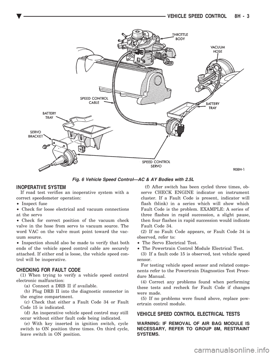
² Inspect fuse
² Check for loose electrical and vacuum connections
at the servo
² Check for correct position of the vacuum check
valve in the hose from servo to vacuum source. The
word VAC on the valve must point toward the vac-
uum source.
² Inspection should also be made to verify that both
ends of the vehicle speed control cable are securely
attached. If either end is loose, the vehicle speed con-
trol will be inoperative.
CHECKING FOR FAULT CODE
(1) When trying to verify a vehicle speed control
electronic malfunction: (a) Connect a DRB II if available.
(b) Plug DRB II into the diagnostic connector in
the engine compartment. (c) Check that either a Fault Code 34 or Fault
Code 15 is indicated. (d) An inoperative vehicle speed control may still
occur without either fault code being indicated. (e) With key inserted in ignition switch, cycle
switch to ON position three times. On third cycle,
leave switch in ON position. (f) After switch has been cycled three times, ob-
serve CHECK ENGINE indicator on instrument
cluster. If a Fault Code is present, indicator will
flash (blink) in a series which will show which
Fault Code is the problem. EXAMPLE: A series of
three flashes in rapid succession, a slight pause,
then four flashes in rapid succession would indicate
Fault Code 34.
(2) If no Fault Code appears, or Fault Code 34 is
observed, refer to:
² The Servo Electrical Test.
² The Powertrain Control Module Electrical Test.
(3) If a fault code 15 is observed, test vehicle speed
sensor. For testing vehicle speed sensor and related compo-
nents refer to the Powertrain Diagnostics Test Proce-
dure Manual. (4) Correct any problems found when performing
these tests and recheck for Fault Code if changes
were made. (5) If no problems were found above, replace pow-
ertrain control module.
VEHICLE SPEED CONTROL ELECTRICAL TESTS
WARNING: IF REMOVAL OF AIR BAG MODULE IS
NECESSARY, REFER TO GROUP 8M, RESTRAINT
SYSTEMS.
Fig. 6 Vehicle Speed ControlÐAC & AY Bodies with 2.5L
Ä VEHICLE SPEED CONTROL 8H - 3
Page 675 of 2438
ILLUMINATED ENTRY SYSTEM INDEX
page page
Body Controller ComputerÐAC, AG, AJ and AY-Body ............................. 34
Diagnostic ProceduresÐAA-Body ............ 33 Diagnostic ProceduresÐAC, AG, AJ and AY-Body . 33
General Information ....................... 33
Illuminated Entry ModuleÐAA-Body ........... 34
GENERAL INFORMATION
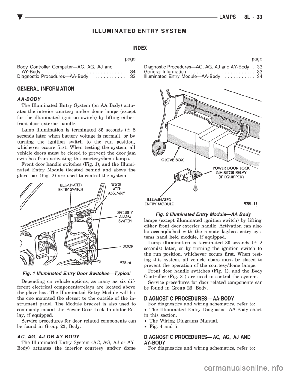
AA-BODY
The Illuminated Entry System (on AA Body) actu-
ates the interior courtesy and/or dome lamps (except
for the illuminated ignition switch) by lifting either
front door exterior handle. Lamp illumination is terminated 35 seconds ( 68
seconds later when battery voltage is normal), or by
turning the ignition switch to the run position,
whichever occurs first. When testing the system, all
vehicle doors must be closed to prevent the door jam
switches from activating the courtesy/dome lamps. Front door handle switches (Fig. 1), and the Illumi-
nated Entry Module (located behind and above the
glove box (Fig. 2) are used to control the system.
Depending on vehicle options, as many as six dif-
ferent electrical components/relays are located above
the glove box. The Illuminated Entry Module will be
the one mounted the closest to the outside of the in-
strument panel. The Module bracket is also used to
commonly mount the Power Door Lock Inhibitor Re-
lay, if equipped. Service procedures for door related components can
be found in Group 23, Body.
AC, AG, AJ OR AY BODY
The Illuminated Entry System (AC, AG, AJ or AY
Body) actuates the interior courtesy and/or dome lamps (except illuminated ignition switch) by lifting
either front door exterior handle. Activation can also
be accomplished with the remote keyless entry sys-
tems hand held module, if equipped. Lamp illumination is terminated 30 seconds ( 62
seconds) later, or by turning the ignition switch to
the run position, whichever occurs first. When test-
ing this system, all vehicle doors must be closed to
prevent the operation of the courtesy/dome lamps. Front door handle switches (Fig. 1), and the Body
Controller (Fig . 3 ) are used to control the system.
Service procedures for door related components can
be found in Group 23, Body.
DIAGNOSTIC PROCEDURESÐAA-BODY
For diagnostics and wiring schematics, refer to:
² The Illuminated Entry DiagnosisÐAA-Body chart
in this section.
² The Wiring Diagrams Manual.
² Fig. 4 and 5.
DIAGNOSTIC PROCEDURESÐAC, AG, AJ AND
AY-BODY
For diagnostics and wiring schematics, refer to:
Fig. 1 Illuminated Entry Door SwitchesÐTypical
Fig. 2 Illuminated Entry ModuleÐAA Body
Ä LAMPS 8L - 33
Page 685 of 2438
SERVICE OF DEPLOYED AIR BAG MODULE
After an air bag has been deployed, the air bag
module and clockspring must be replaced because
they cannot be reused. Other air bag system compo-
nents are replaced if damaged.
SCHEDULED MAINTENANCE INSPECTION
Vehicles equipped with a Air Bag System must be
inspected every three years or 30,000 miles / 48,000
Km. The following items should be inspected. (1) Inspect components for damage or deteriora-
tion. (a) If the air bag module housing shows signs of
physical damage or abuse, replace the module. (b) Check that both front impact sensors are
properly installed to the upper crossmember of the
radiator closure panel. Repair as required.
(2) Check the air bag warning lamp for proper op-
eration as follows: (a) Turn ignition switch to the ON position, the
air bag warning lamp should light. If not, test the system using the DRB II and Passive Restraint
System Diagnostic Procedures Manual. Repair as
required.
(b) The air bag warning lamp lights, but fails to go
out after ten seconds. Test the system using the DRB
II and Passive Restraint System Diagnostic Proce-
dures Manual. Repair as required. (c) Erasing of fault codes is not required.
AIR BAG SYSTEM CHECK
WARNING: BEFORE BEGINNING ANY AIR BAG SYS-
TEM CHECK PROCEDURES, REMOVE AND ISOLATE
THE BATTERY NEGATIVE (-) CABLE (GROUND)
FROM THE VEHICLE BATTERY. THIS IS THE ONLY
SURE WAY TO DISABLE THE AIR BAG SYSTEM.
FAILURE TO DO THIS COULD RESULT IN ACCIDEN-
TAL AIR BAG DEPLOYMENT AND POSSIBLE PER-
SONAL INJURY.
WHEN AN UNDEPLOYED AIR BAG ASSEMBLY IS
TO BE REMOVED FROM THE STEERING WHEEL,
DISCONNECT BATTERY GROUND CABLE AND
ISOLATE. ALLOW SYSTEM CAPACITOR TO DIS-
CHARGE FOR TWO MINUTES, THEN BEGIN AIR
BAG REMOVAL. (1) Disconnect the battery negative cable and iso-
late. (2) Remove forward console or cover as necessary.
(3) Connect DRB II to ASDM diagnostic 6-way con-
nector, located at right side of module. (4) Turn the ignition key to ON position. Exit vehicle
with DRB II. Use the latest version of the proper
cartridge. (5) After checking that no one is inside the vehicle,
connect the negative battery cable. (6) Using the DRB II, read and record active fault
data. (7) Read and record any stored faults.
(8) Refer to the Passive Restraint Diagnostic Test
Manual if any faults are found in steps 6 and 7. (9) Erase stored faults if there are no active fault
codes. If problems remain, fault codes will not erase. (10) With the ignition key in the ON position, make
sure no one is in the vehicle. (11) From the passenger side of vehicle, turn the
ignition key to OFF then ON and observe the instru-
ment cluster air bag lamp. It should go on for 6 to 8
seconds, then go out; indicating system is functioning
normally. If air bag warning lamp either fails to light,
blinks on and off or goes on and stays on, there is
a system malfunction. Refer to the Passive Re-
straint Diagnostic Test Manual to diagnose the
problem.
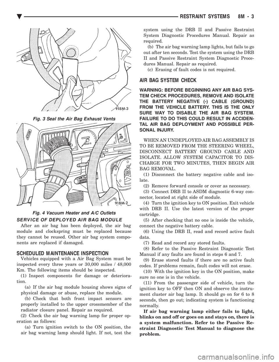
Fig. 3 Seal the Air Bag Exhaust Vents
Fig. 4 Vacuum Heater and A/C Outlets
Ä RESTRAINT SYSTEMS 8M - 3