fuse box location CHEVROLET PLYMOUTH ACCLAIM 1993 Service Manual
[x] Cancel search | Manufacturer: CHEVROLET, Model Year: 1993, Model line: PLYMOUTH ACCLAIM, Model: CHEVROLET PLYMOUTH ACCLAIM 1993Pages: 2438, PDF Size: 74.98 MB
Page 232 of 2438

The primary functions of the (CAB) are:
² (1) Detect wheel locking tendencies.
² (2) Control fluid modulation to the brakes while in
Anti-Lock mode.
² (3) Monitor the system for proper operation.
² (4) Provide communication to the DRB II while in
diagnostic mode. The (CAB) continuously monitors the speed of each
wheel, through the signals generated at the Wheel
Speed Sensors, to determine if any wheel is begin-
ning to lock. When a wheel locking tendency is de-
tected, the (CAB) will isolate the master cylinder
from the wheel brakes. This is done by activating the
Isolation Valves. The (CAB) then commands the ap-
propriate Build or Decay valves to modulate brake
fluid pressure in some or all of the hydraulic circuits.
The fluid used for modulation comes from the booster
servo circuit. The (CAB) continues to control pres-
sure in individual hydraulic circuits until a locking
tendency is no longer present. The (ABS) system is constantly monitored by the
(CAB) for proper operation. If the (CAB) detects a
fault, it can disable the Anti-Lock braking function.
Depending on the fault, the (CAB) will light one or
both of the brake warning lamps. The (CAB) contains a System Diagnostic Program
which triggers the brake system warning lamps
when a system fault is detected. Faults are stored in
a diagnostic program memory. There are 19 fault
codes that may be stored in the (CAB) and displayed
through the DRB II. These fault codes will remain in
the (CAB) memory even after the ignition has been
turned off. These fault codes will remain in memory
until they are cleared with the DRB II, or automati-
cally erased from the memory after (50) ignition
switch on/off cycles.
CONTROLLER ANTI-LOCK BRAKE (INPUTS)
² Four wheel speed sensors.
² Boost pressure transducer.
² Primary pressure transducer.
² Low fluid level switch.
² Differential pressure switch.
² Parking brake switch.
² Dual function pressure switch (warning pressure
only)
² Stop lamp switch.
² Ignition switch.
² System relay voltage.
² Ground.
² Low Accumulator
CONTROLLER ANTI-LOCK BRAKE (OUTPUTS)
²Ten modulator valves-3 decay, 3 build and 4 isola-
tion.
² Red Brake warning lamp.
² Amber Anti-Lock Warning Lamp.
² System relay actuation. ²
Diagnostic communication.
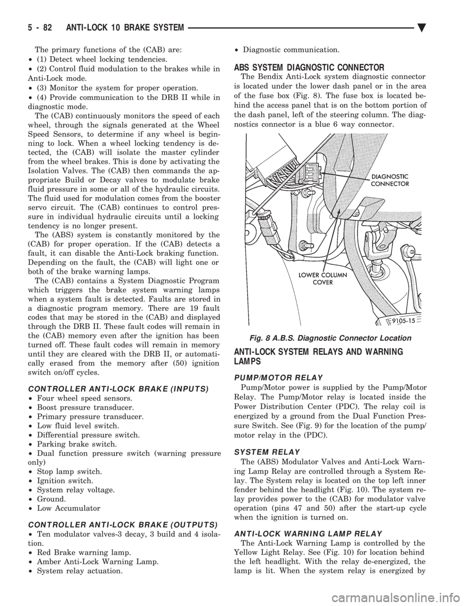
ABS SYSTEM DIAGNOSTIC CONNECTOR
The Bendix Anti-Lock system diagnostic connector
is located under the lower dash panel or in the area
of the fuse box (Fig. 8). The fuse box is located be-
hind the access panel that is on the bottom portion of
the dash panel, left of the steering column. The diag-
nostics connector is a blue 6 way connector.
ANTI-LOCK SYSTEM RELAYS AND WARNING
LAMPS
PUMP/MOTOR RELAY
Pump/Motor power is supplied by the Pump/Motor
Relay. The Pump/Motor relay is located inside the
Power Distribution Center (PDC). The relay coil is
energized by a ground from the Dual Function Pres-
sure Switch. See (Fig. 9) for the location of the pump/
motor relay in the (PDC).
SYSTEM RELAY
The (ABS) Modulator Valves and Anti-Lock Warn-
ing Lamp Relay are controlled through a System Re-
lay. The System relay is located on the top left inner
fender behind the headlight (Fig. 10). The system re-
lay provides power to the (CAB) for modulator valve
operation (pins 47 and 50) after the start-up cycle
when the ignition is turned on.
ANTI-LOCK WARNING LAMP RELAY
The Anti-Lock Warning Lamp is controlled by the
Yellow Light Relay. See (Fig. 10) for location behind
the left headlight. With the relay de-energized, the
lamp is lit. When the system relay is energized by
Fig. 8 A.B.S. Diagnostic Connector Location
5 - 82 ANTI-LOCK 10 BRAKE SYSTEM Ä
Page 531 of 2438

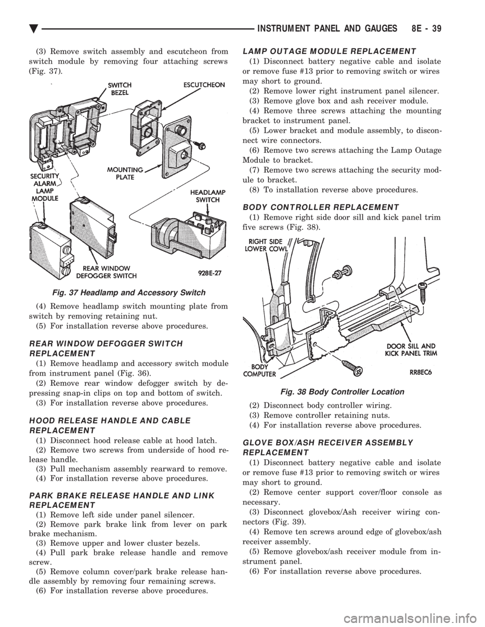
(3) Remove switch assembly and escutcheon from
switch module by removing four attaching screws
(Fig. 37).
(4) Remove headlamp switch mounting plate from
switch by removing retaining nut. (5) For installation reverse above procedures.
REAR WINDOW DEFOGGER SWITCHREPLACEMENT
(1) Remove headlamp and accessory switch module
from instrument panel (Fig. 36). (2) Remove rear window defogger switch by de-
pressing snap-in clips on top and bottom of switch. (3) For installation reverse above procedures.
HOOD RELEASE HANDLE AND CABLEREPLACEMENT
(1) Disconnect hood release cable at hood latch.
(2) Remove two screws from underside of hood re-
lease handle. (3) Pull mechanism assembly rearward to remove.
(4) For installation reverse above procedures.
PARK BRAKE RELEASE HANDLE AND LINK REPLACEMENT
(1) Remove left side under panel silencer.
(2) Remove park brake link from lever on park
brake mechanism. (3) Remove upper and lower cluster bezels.
(4) Pull park brake release handle and remove
screw. (5) Remove column cover/park brake release han-
dle assembly by removing four remaining screws. (6) For installation reverse above procedures.
LAMP OUTAGE MODULE REPLACEMENT
(1) Disconnect battery negative cable and isolate
or remove fuse #13 prior to removing switch or wires
may short to ground. (2) Remove lower right instrument panel silencer.
(3) Remove glove box and ash receiver module.
(4) Remove three screws attaching the mounting
bracket to instrument panel. (5) Lower bracket and module assembly, to discon-
nect wire connectors. (6) Remove two screws attaching the Lamp Outage
Module to bracket. (7) Remove two screws attaching the security mod-
ule to bracket. (8) To installation reverse above procedures.
BODY CONTROLLER REPLACEMENT
(1) Remove right side door sill and kick panel trim
five screws (Fig. 38).
(2) Disconnect body controller wiring.
(3) Remove controller retaining nuts.
(4) For installation reverse above procedures.
GLOVE BOX/ASH RECEIVER ASSEMBLY REPLACEMENT
(1) Disconnect battery negative cable and isolate
or remove fuse #13 prior to removing switch or wires
may short to ground. (2) Remove center support cover/floor console as
necessary. (3) Disconnect glovebox/Ash receiver wiring con-
nectors (Fig. 39). (4) Remove ten screws around edge of glovebox/ash
receiver assembly. (5) Remove glovebox/ash receiver module from in-
strument panel. (6) For installation reverse above procedures.
Fig. 37 Headlamp and Accessory Switch
Fig. 38 Body Controller Location
Ä INSTRUMENT PANEL AND GAUGES 8E - 39
Page 595 of 2438

² If no short to ground at connector, check speaker
resistance at amplifier connector for an reading of
three to five ohms.
² If resistance is OK, refer to Radio Diagnosis. If ra-
dio checks OK, replace amplifier.
² If resistance is less than three ohms check
speaker. Check across the speaker connector if less
than three ohms replace speaker. If resistance is OK
repair wires
CONDITION: MECHANICAL NOISE DISTORTION
² Check trim for loose parts and speaker attach-
ments for buzzes
² Remove speaker still connected and listen for dis-
tortion. Distortion replace speaker.
CONDITION: ONE SPEAKER NON-OPERATIVE
² Remove output signal connector from amplifier
and check for three to five ohms resistance to the
non-operative speaker. Refer to Fig. 34 for the appro-
priate pin numbers.
² If resistance is less than three ohms, test speaker
for resistance.
² If OK repair wire. If not replace speaker.
CONDITION: ALL SPEAKERS NON-OPERATIVE
²Check radio for being ON, are the display lights
on
² Radio not ON, refer to Radio Diagnosis
² Check Amplifier Connectors and wires for proper
connection
² Check pin 9 and pin 27 for battery voltage
² If voltage OK replace amplifier ²
If pin 27 has battery voltage and pin 9 has 0 volt-
age. Refer to Power Antenna Diagnosis and test volt-
age at antenna relay.
² If pin 9 has battery voltage and pin 27 has 0 volt-
age. Check pin 27 for short to ground.
² If shorted to ground repair wire
² If no short to ground check fuse cavity number 16
for blown fuse.
² If fuse blows again replace amplifier
RELAY/CHOKEÐINFINITY SPEAKER
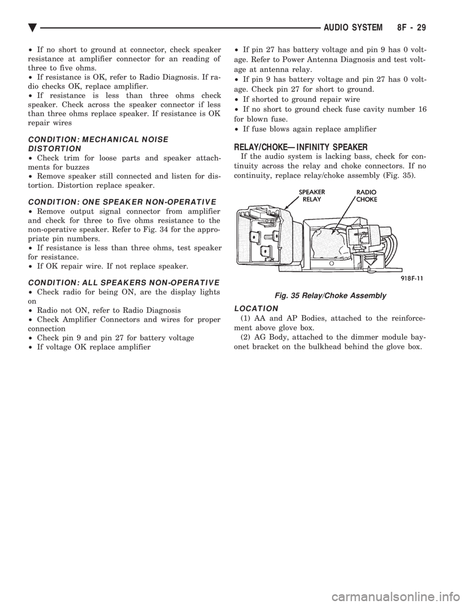
If the audio system is lacking bass, check for con-
tinuity across the relay and choke connectors. If no
continuity, replace relay/choke assembly (Fig. 35).
LOCATION
(1) AA and AP Bodies, attached to the reinforce-
ment above glove box. (2) AG Body, attached to the dimmer module bay-
onet bracket on the bulkhead behind the glove box.
Fig. 35 Relay/Choke Assembly
Ä AUDIO SYSTEM 8F - 29
Page 753 of 2438

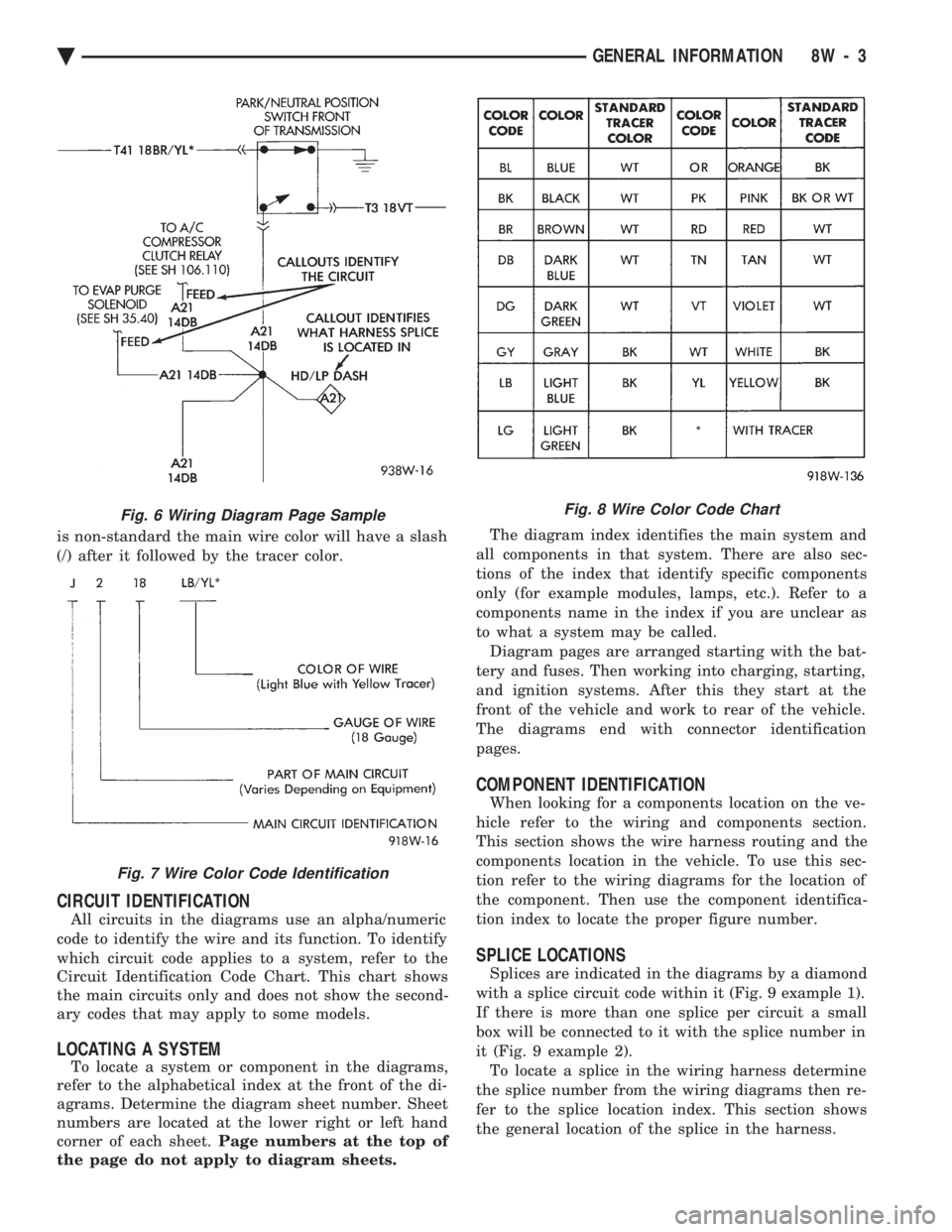
is non-standard the main wire color will have a slash
(/) after it followed by the tracer color.
CIRCUIT IDENTIFICATION
All circuits in the diagrams use an alpha/numeric
code to identify the wire and its function. To identify
which circuit code applies to a system, refer to the
Circuit Identification Code Chart. This chart shows
the main circuits only and does not show the second-
ary codes that may apply to some models.
LOCATING A SYSTEM
To locate a system or component in the diagrams,
refer to the alphabetical index at the front of the di-
agrams. Determine the diagram sheet number. Sheet
numbers are located at the lower right or left hand
corner of each sheet. Page numbers at the top of
the page do not apply to diagram sheets. The diagram index identifies the main system and
all components in that system. There are also sec-
tions of the index that identify specific components
only (for example modules, lamps, etc.). Refer to a
components name in the index if you are unclear as
to what a system may be called. Diagram pages are arranged starting with the bat-
tery and fuses. Then working into charging, starting,
and ignition systems. After this they start at the
front of the vehicle and work to rear of the vehicle.
The diagrams end with connector identification
pages.
COMPONENT IDENTIFICATION
When looking for a components location on the ve-
hicle refer to the wiring and components section.
This section shows the wire harness routing and the
components location in the vehicle. To use this sec-
tion refer to the wiring diagrams for the location of
the component. Then use the component identifica-
tion index to locate the proper figure number.
SPLICE LOCATIONS
Splices are indicated in the diagrams by a diamond
with a splice circuit code within it (Fig. 9 example 1).
If there is more than one splice per circuit a small
box will be connected to it with the splice number in
it (Fig. 9 example 2). To locate a splice in the wiring harness determine
the splice number from the wiring diagrams then re-
fer to the splice location index. This section shows
the general location of the splice in the harness.
Fig. 6 Wiring Diagram Page Sample
Fig. 7 Wire Color Code Identification
Fig. 8 Wire Color Code Chart
Ä GENERAL INFORMATION 8W - 3