length CHEVROLET PLYMOUTH ACCLAIM 1993 Service Manual
[x] Cancel search | Manufacturer: CHEVROLET, Model Year: 1993, Model line: PLYMOUTH ACCLAIM, Model: CHEVROLET PLYMOUTH ACCLAIM 1993Pages: 2438, PDF Size: 74.98 MB
Page 60 of 2438
FRONT SUSPENSION
FRONT SUSPENSION MAJOR COMPONENTS (FIG. 2)
STRUT SUPPORT
The system is supported by coil springs positioned
offset around the struts. The springs are contained
between an upper seat, located just below the top
strut mount assembly (Fig. 2) and a lower spring
seat on the strut lower housing. The top of each strut assembly is bolted to the up-
per fender reinforcement (shock tower) through a
rubber isolated mount. The bottom attaches to the top of the steering
knuckle with two through bolts. On some vehicles,
one bolt has an eccentric cam located below the head
of the bolt for camber adjustment. On the other ve-
hicles the camber adjustment is done by manually
moving the steering knuckle within the strut assem-
bly. Caster is a fixed setting on all vehicles and is
not adjustable.
STEERING KNUCKLE
The steering knuckle is a single casting with legs
machined for attachment to the strut damper, steer-
ing linkage, brake adaptor, and lower control arm
ball joint. The knuckle also holds the front drive hub
bearing. The hub is positioned through the bearing
and knuckle, with the constant velocity stub shaft
splined through the hub.
LOWER CONTROL ARM
The lower control arm is a steel casting with 2
large spool type rubber pivot bushings. The lower
control arm is bolted to the crossmember with pivot
bolts through the center of the rubber pivot bush-
ings. The ball joint is pressed into the control arm and
has a non-tapered stud with a notch for clamp bolt
clearance. The stud is clamped and locked into the
steering knuckle leg with a clamp bolt. The lower control arms are inter-connected through
a rubber isolated sway bar (Fig. 2).
DRIVESHAFTS
A left and right driveshaft is attached inboard to
the transaxle differential side gears, and outboard to
the driven wheel hub. To deliver driving force from the transaxle to the
front wheels during turning maneuvers and suspen-
sion movement. Both shafts are constructed with con-
stant velocity universal joints at both ends. Both shafts have a Tripod (sliding) joint at the
transaxle end and Rzeppa joints (with splined stub
shafts) on the hub ends. Due to the transaxle loca-
tion the connecting shafts between the C/V joints are
of different length and construction. The right shaft
is longer and of tubular construction. The left shaft
is solid.
2 - 2 SUSPENSION AND DRIVESHAFTS Ä
Page 83 of 2438
DRIVESHAFTS INDEX
page page
C/V Joint Boots Handling and Cleaning ........ 44
Damper Weights ......................... 48
Driveshaft Identification .................... 27
Driveshaft Positioning Specifications .......... 48
Driveshaft Reconditioning Procedure .......... 31
Driveshafts, Remove Install ................. 27 General Information
....................... 25
Inner C/V Joint .......................... 32
Intermediate Shaft Assembly Recondition ...... 41
Outer C/V Joint .......................... 37
Service Procedures ....................... 27
GENERAL INFORMATION
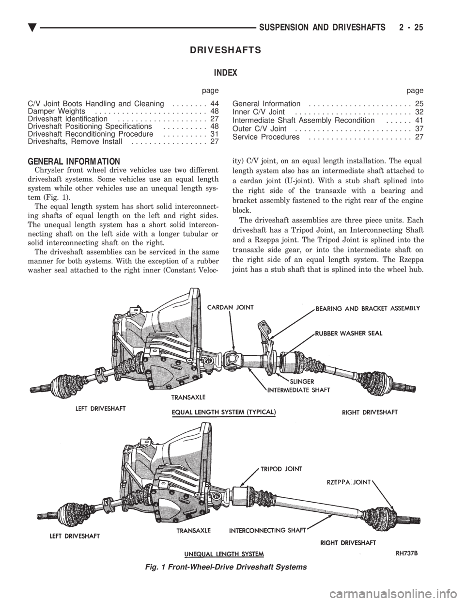
Chrysler front wheel drive vehicles use two different
driveshaft systems. Some vehicles use an equal length
system while other vehicles use an unequal length sys-
tem (Fig. 1). The equal length system has short solid interconnect-
ing shafts of equal length on the left and right sides.
The unequal length system has a short solid intercon-
necting shaft on the left side with a longer tubular or
solid interconnecting shaft on the right.
The driveshaft assemblies can be serviced in the same
manner for both systems. With the exception of a rubber
washer seal attached to the right inner (Constant Veloc- ity) C/V joint, on an equal length installation. The equal
length system also has an intermediate shaft attached to
a cardan joint (U-joint). With a stub shaft splined into
the right side of the transaxle with a bearing and
bracket assembly fastened to the right rear of the engine
block.
The driveshaft assemblies are three piece units. Each
driveshaft has a Tripod Joint, an Interconnecting Shaft
and a Rzeppa joint. The Tripod Joint is splined into the
transaxle side gear, or into the intermediate shaft on
the right side of an equal length system. The Rzeppa
joint has a stub shaft that is splined into the wheel hub.
Fig. 1 Front-Wheel-Drive Driveshaft Systems
Ä SUSPENSION AND DRIVESHAFTS 2 - 25
Page 85 of 2438
DRIVESHAFT IDENTIFICATION
Driveshafts are identified by the manufacturer. Vehi-
cles can be equipped with any of these driveshaft as-
semblies. Each assembly can be identified as shown in
(Fig. 2).
SERVICE PROCEDURES
Procedures for the removal and installation of the
driveshafts are essentially the same for all front
wheel drive vehicles. Each driveshaft has a spring
within the inboard Tripod C/V joint that maintains
constant engagement with the transaxle. This allows
the drive shaft to be removed without dismantling
part of the transaxle.
CAUTION: Boot sealing is vital to retain special lu-
bricants and to prevent foreign contaminants from
entering the C/V joint. Mishandling, such as allow-
ing the assemblies to dangle unsupported, pulling
or pushing the ends can cut boots or damage C/V
joints. During removal and installation procedures
always support both ends of the driveshaft to pre-
vent damage.
DRIVESHAFTS, REMOVE INSTALL
HUB NUT REMOVAL
Hub nut removal and installation is the same for
all front wheel drive vehicles. For installation see
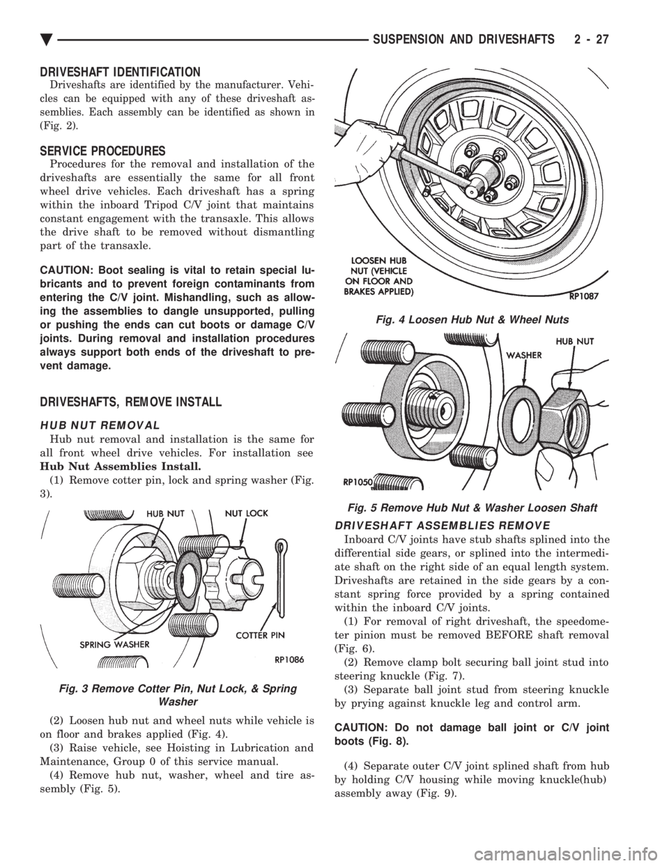
Hub Nut Assemblies Install. (1) Remove cotter pin, lock and spring washer (Fig.
3).
(2) Loosen hub nut and wheel nuts while vehicle is
on floor and brakes applied (Fig. 4). (3) Raise vehicle, see Hoisting in Lubrication and
Maintenance, Group 0 of this service manual. (4) Remove hub nut, washer, wheel and tire as-
sembly (Fig. 5).
DRIVESHAFT ASSEMBLIES REMOVE
Inboard C/V joints have stub shafts splined into the
differential side gears, or splined into the intermedi-
ate shaft on the right side of an equal length system.
Driveshafts are retained in the side gears by a con-
stant spring force provided by a spring contained
within the inboard C/V joints. (1) For removal of right driveshaft, the speedome-
ter pinion must be removed BEFORE shaft removal
(Fig. 6). (2) Remove clamp bolt securing ball joint stud into
steering knuckle (Fig. 7). (3) Separate ball joint stud from steering knuckle
by prying against knuckle leg and control arm.
CAUTION: Do not damage ball joint or C/V joint
boots (Fig. 8). (4) Separate outer C/V joint splined shaft from hub
by holding C/V housing while moving knuckle(hub)
assembly away (Fig. 9).
Fig. 3 Remove Cotter Pin, Nut Lock, & Spring Washer
Fig. 4 Loosen Hub Nut & Wheel Nuts
Fig. 5 Remove Hub Nut & Washer Loosen Shaft
Ä SUSPENSION AND DRIVESHAFTS 2 - 27
Page 86 of 2438
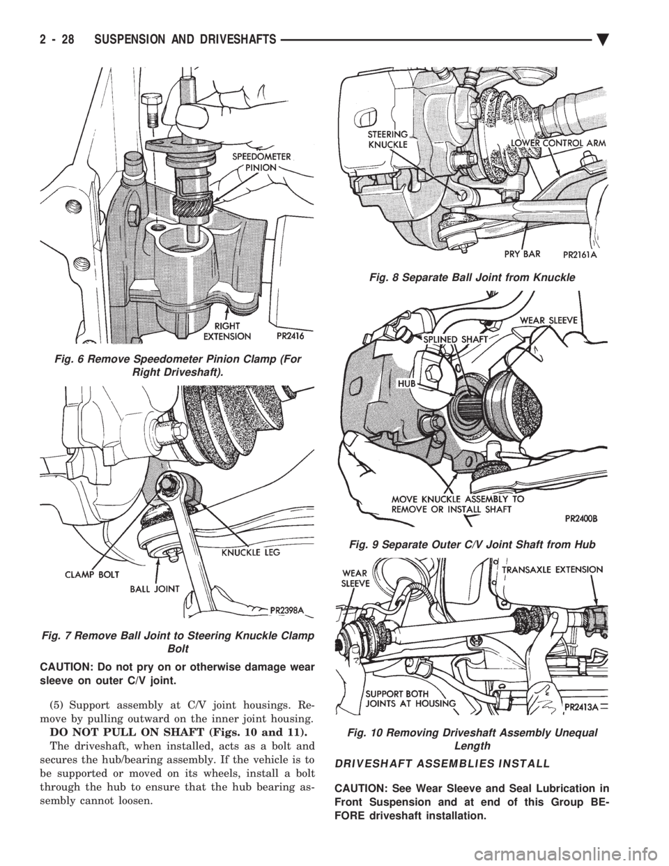
CAUTION: Do not pry on or otherwise damage wear
sleeve on outer C/V joint. (5) Support assembly at C/V joint housings. Re-
move by pulling outward on the inner joint housing. DO NOT PULL ON SHAFT (Figs. 10 and 11).
The driveshaft, when installed, acts as a bolt and
secures the hub/bearing assembly. If the vehicle is to
be supported or moved on its wheels, install a bolt
through the hub to ensure that the hub bearing as-
sembly cannot loosen.
DRIVESHAFT ASSEMBLIES INSTALL
CAUTION: See Wear Sleeve and Seal Lubrication in
Front Suspension and at end of this Group BE-
FORE driveshaft installation.
Fig. 6 Remove Speedometer Pinion Clamp (For Right Driveshaft).
Fig. 7 Remove Ball Joint to Steering Knuckle Clamp Bolt
Fig. 8 Separate Ball Joint from Knuckle
Fig. 9 Separate Outer C/V Joint Shaft from Hub
Fig. 10 Removing Driveshaft Assembly UnequalLength
2 - 28 SUSPENSION AND DRIVESHAFTS Ä
Page 87 of 2438
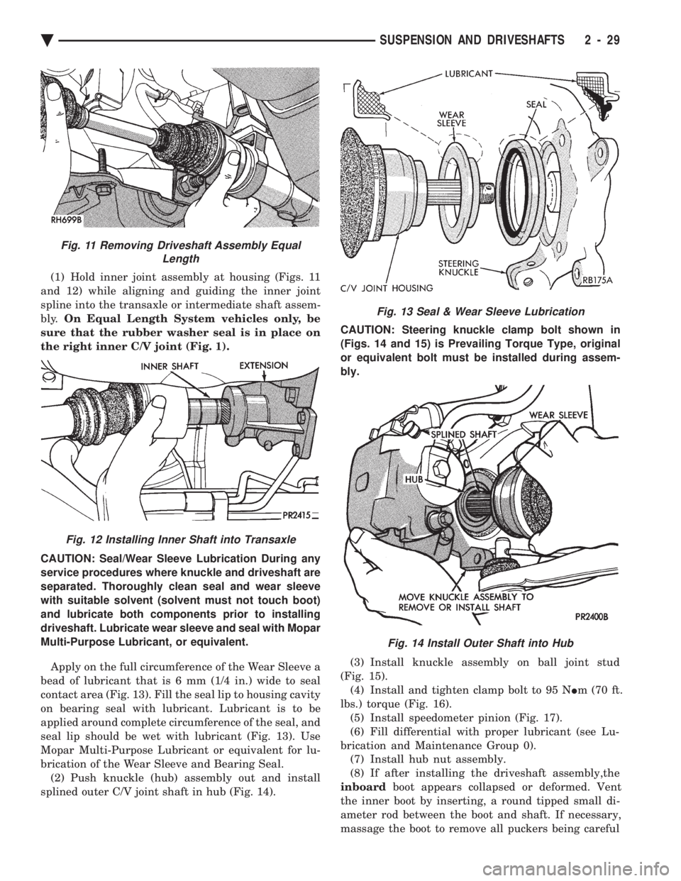
(1) Hold inner joint assembly at housing (Figs. 11
and 12) while aligning and guiding the inner joint
spline into the transaxle or intermediate shaft assem-
bly. On Equal Length System vehicles only, be
sure that the rubber washer seal is in place on
the right inner C/V joint (Fig. 1).
CAUTION: Seal/Wear Sleeve Lubrication During any
service procedures where knuckle and driveshaft are
separated. Thoroughly clean seal and wear sleeve
with suitable solvent (solvent must not touch boot)
and lubricate both components prior to installing
driveshaft. Lubricate wear sleeve and seal with Mopar
Multi-Purpose Lubricant, or equivalent.
Apply on the full circumference of the Wear Sleeve a
bead of lubricant that is 6 mm (1/4 in.) wide to seal
contact area (Fig. 13). Fill the seal lip to housing cavity
on bearing seal with lubricant. Lubricant is to be
applied around complete circumference of the seal, and
seal lip should be wet with lubricant (Fig. 13). Use
Mopar Multi-Purpose Lubricant or equivalent for lu-
brication of the Wear Sleeve and Bearing Seal. (2) Push knuckle (hub) assembly out and install
splined outer C/V joint shaft in hub (Fig. 14). CAUTION: Steering knuckle clamp bolt shown in
(Figs. 14 and 15) is Prevailing Torque Type, original
or equivalent bolt must be installed during assem-
bly.
(3) Install knuckle assembly on ball joint stud
(Fig. 15). (4) Install and tighten clamp bolt to 95 N Im (70 ft.
lbs.) torque (Fig. 16). (5) Install speedometer pinion (Fig. 17).
(6) Fill differential with proper lubricant (see Lu-
brication and Maintenance Group 0). (7) Install hub nut assembly.
(8) If after installing the driveshaft assembly,the
inboard boot appears collapsed or deformed. Vent
the inner boot by inserting, a round tipped small di-
ameter rod between the boot and shaft. If necessary,
massage the boot to remove all puckers being careful
Fig. 13 Seal & Wear Sleeve Lubrication
Fig. 14 Install Outer Shaft into Hub
Fig. 11 Removing Driveshaft Assembly Equal Length
Fig. 12 Installing Inner Shaft into Transaxle
Ä SUSPENSION AND DRIVESHAFTS 2 - 29
Page 92 of 2438
INSPECT TRIPOD AND HOUSING
Remove as much grease as possible from assembly
and inspect joint housing ball raceway and tripod components for EXCESSIVE wear and replace if nec-
essary.
Inspect the spring, spring cup, and the spherical end
of the connecting shaft for EXCESSIVE wear or dam-
age and replace, if necessary.
ASSEMBLE C/V JOINT
TRIPOD ASSEMBLY INSTALLATION G.K.N.
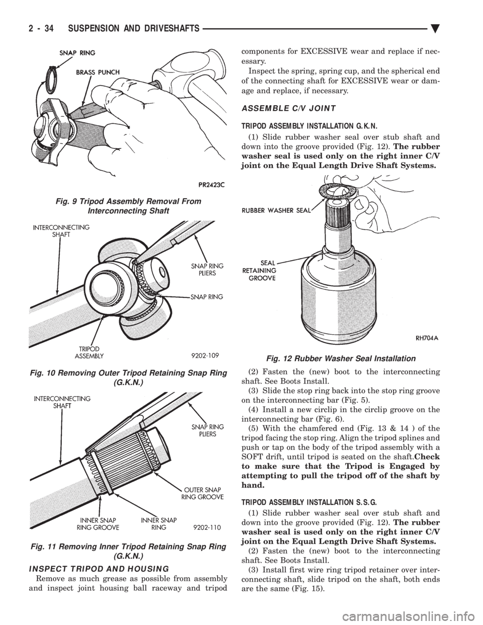
(1) Slide rubber washer seal over stub shaft and
down into the groove provided (Fig. 12). The rubber
washer seal is used only on the right inner C/V
joint on the Equal Length Drive Shaft Systems.
(2) Fasten the (new) boot to the interconnecting
shaft. See Boots Install. (3) Slide the stop ring back into the stop ring groove
on the interconnecting bar (Fig. 5). (4) Install a new circlip in the circlip groove on the
interconnecting bar (Fig. 6). (5) With the chamfered end (Fig. 13 & 14 ) of the
tripod facing the stop ring. Align the tripod splines and
push or tap on the body of the tripod assembly with a
SOFT drift, until tripod is seated on the shaft. Check
to make sure that the Tripod is Engaged by
attempting to pull the tripod off of the shaft by
hand.
TRIPOD ASSEMBLY INSTALLATION S.S.G. (1) Slide rubber washer seal over stub shaft and
down into the groove provided (Fig. 12). The rubber
washer seal is used only on the right inner C/V
joint on the Equal Length Drive Shaft Systems. (2) Fasten the (new) boot to the interconnecting
shaft. See Boots Install. (3) Install first wire ring tripod retainer over inter-
connecting shaft, slide tripod on the shaft, both ends
are the same (Fig. 15).
Fig. 9 Tripod Assembly Removal From Interconnecting Shaft
Fig. 10 Removing Outer Tripod Retaining Snap Ring (G.K.N.)
Fig. 11 Removing Inner Tripod Retaining Snap Ring(G.K.N.)
Fig. 12 Rubber Washer Seal Installation
2 - 34 SUSPENSION AND DRIVESHAFTS Ä
Page 99 of 2438
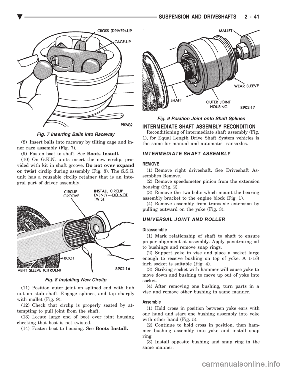
(8) Insert balls into raceway by tilting cage and in-
ner race assembly (Fig. 7). (9) Fasten boot to shaft. See Boots Install.
(10) On G.K.N. units insert the new circlip, pro-
vided with kit in shaft groove. Do not over expand
or twist circlip during assembly (Fig. 8). The S.S.G.
unit has a reusable circlip retainer that is an inte-
gral part of driver assembly.
(11) Position outer joint on splined end with hub
nut on stub shaft. Engage splines, and tap sharply
with mallet (Fig. 9). (12) Check that circlip is properly seated by at-
tempting to pull joint from the shaft. (13) Locate large end of boot over joint housing
checking that boot is not twisted. (14) Fasten boot to housing. See Boots Install.
INTERMEDIATE SHAFT ASSEMBLY RECONDITION
Reconditioning of intermediate shaft assembly (Fig.
1), for Equal Length Drive Shaft System vehicles is
the same for manual and automatic transaxles.
INTERMEDIATE SHAFT ASSEMBLY
REMOVE
(1) Remove right driveshaft. See Driveshaft As-
semblies Remove. (2) Remove speedometer pinion from the extension
housing (Fig. 2). (3) Remove the two bolts which mount the bearing
assembly bracket to the engine block (Fig. 1). (4) Remove assembly from transaxle extension by
pulling outward on the yoke (Fig. 3).
UNIVERSAL JOINT AND ROLLER
Disassemble
(1) Mark relationship of shaft to shaft to ensure
proper alignment at assembly. Apply penetrating oil
to bushings and remove snap rings. (2) Support yoke in vise and place a socket large
enough to receive bushing on top of yoke. A 1-1/8
inch socket is suitable (Fig. 4). (3) Striking socket with hammer will cause yoke to
move down and bushing to move up out of yoke into
socket. (4) After removing one bushing, turn parts in a
vise and remove other bushing in same manner.
Assemble (1) Hold cross in position between yoke ears with
one hand and start one bushing assembly into yoke
with other hand (Fig. 5). (2) Continue to hold cross in position, then ham-
mer bushing assembly into yoke and install snap
ring. (3) Install opposite bushing and snap ring in the
same manner.
Fig. 7 Inserting Balls into Raceway
Fig. 8 Installing New Circlip
Fig. 9 Position Joint onto Shaft Splines
Ä SUSPENSION AND DRIVESHAFTS 2 - 41
Page 107 of 2438
mount have been loosened for any reason, or if vehicle
has experienced front structural damage, driveshaft
lengths must be checked and corrected, if required. A
shorter than required driveshaft length can result in ob-
jectionable noise. A longer than required driveshaft
length may result in potential damage.
Use of the following procedure will ensure satisfac-
tory driveshaft engagement under all normal vehicle
operating conditions. (1) The vehicle must be completely assembled.
Front wheels must be properly aligned and in the
straight ahead position. The vehicle must be in a po-
sition so that the full weight of the body is distrib-
uted to all four tires. A platform hoist, or front end
alignment rack, is recommended.
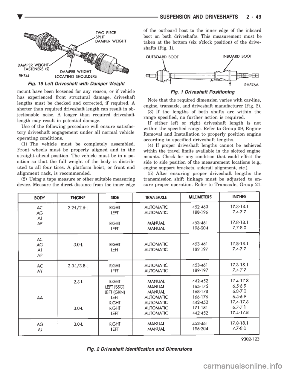
(2) Using a tape measure or other suitable measuring
device. Measure the direct distance from the inner edge of the outboard boot to the inner edge of the inboard
boot on both driveshafts. This measurement must be
taken at the bottom (six o'clock position) of the drive-
shafts (Fig. 1).
Note that the required dimension varies with car-line,
engine, transaxle, and driveshaft manufacturer (Fig. 2).
(3) If the lengths of both shafts are within the
range specified, no further action is required. If either left or right driveshaft length is not
within the specified range. Refer to Group 09, Engine
Removal and Installation to properly position engine
according to specified driveshaft lengths.
(4) If proper driveshaft lengths cannot be achieved
within the travel limits available in the slotted engine
mounts. Check for any condition that could effect the
side to side position of the measurement locations (e.g.,
engine support brackets, siderail alignment, etc.).
(5) After ensuring proper driveshaft lengths the
transmission shift linkage must be adjusted to en-
sure proper operation. Refer to Transaxle, Group 21.
Fig. 2 Driveshaft Identification and Dimensions
Fig. 19 Left Driveshaft with Damper Weight
Fig. 1 Driveshaft Positioning
Ä SUSPENSION AND DRIVESHAFTS 2 - 49
Page 161 of 2438
BRAKE HOSE AND TUBING
INSPECTION OF BRAKE HOSE AND TUBING
Flexible rubber hose is used at both front brakes and
at the rear axle. Inspection of brake hoses should be
performed whenever the brake system is serviced and
every 7,500 miles or 12 months, whichever comes first
(every engine oil change). Inspect hydraulic brake
hoses for severe surface cracking, scuffing, or worn
spots. Should the fabric casing of the rubber hose be
exposed due to cracks or abrasions in the rubber hose
cover, the hose should be replaced immediately. Even-
tual deterioration of the hose can take place with
possible burst failure. Faulty installation can cause
twisting and wheel, tire or chassis interference. The steel brake tubing should be inspected periodi-
cally for evidence of physical damage or contact with
moving or hot components.
INSTALLATION OF BRAKE HOSE
Always use factory recommended brake hose to en-
sure quality, correct length and superior fatigue life.
Care should be taken to make sure that the tube and
hose mating surfaces are clean and free from nicks and
burrs. Front right and left side hoses are not
interchangeable. Connections should be correct and properly made.
Use new copper seal washers on all connections using
Banjo Bolts and tighten all fittings to their specified
torques. The flexible front hydraulic brake hose should al-
ways be installed on the vehicle by first attaching the
Banjo connector to the caliper assembly. Then bolt the
intermediate hose bracket to the strut assembly allow-
ing the bracket to position the hose to prevent twisting.
Attach the hose to the body bracket and steel brake
tubing. Tighten all fittings to specified torque. The
body bracket and hose end are keyed so that they will
only fit one way. Install rear brake hoses first to the trailing arm
tubes and then to the floor pan tubes. Minimize hose
twisting. Vehicles equipped with rear disc brakes have
brake hoses attached to the caliper on each side. The
brake hose should be first attached by the Banjo bolt to
the caliper and then secured to the hose bracket with
the retaining clip. The attach the steel brake tubing to
the hose fitting.
REPAIR AND INSTALLATION OF BRAKE TUB- ING
Only double wall 4.75mm (3/16 in.) steel tubing
should be used for replacement. Care should be taken
when replacing brake tubing, to be sure the proper
bending and flaring tools and procedures are used, to
avoid kinking. Do not route the tubes against sharp edges, moving components or into hot areas. All
tubes should be properly attached with recommended
retaining clips.
TYPES OF TUBING FLARES
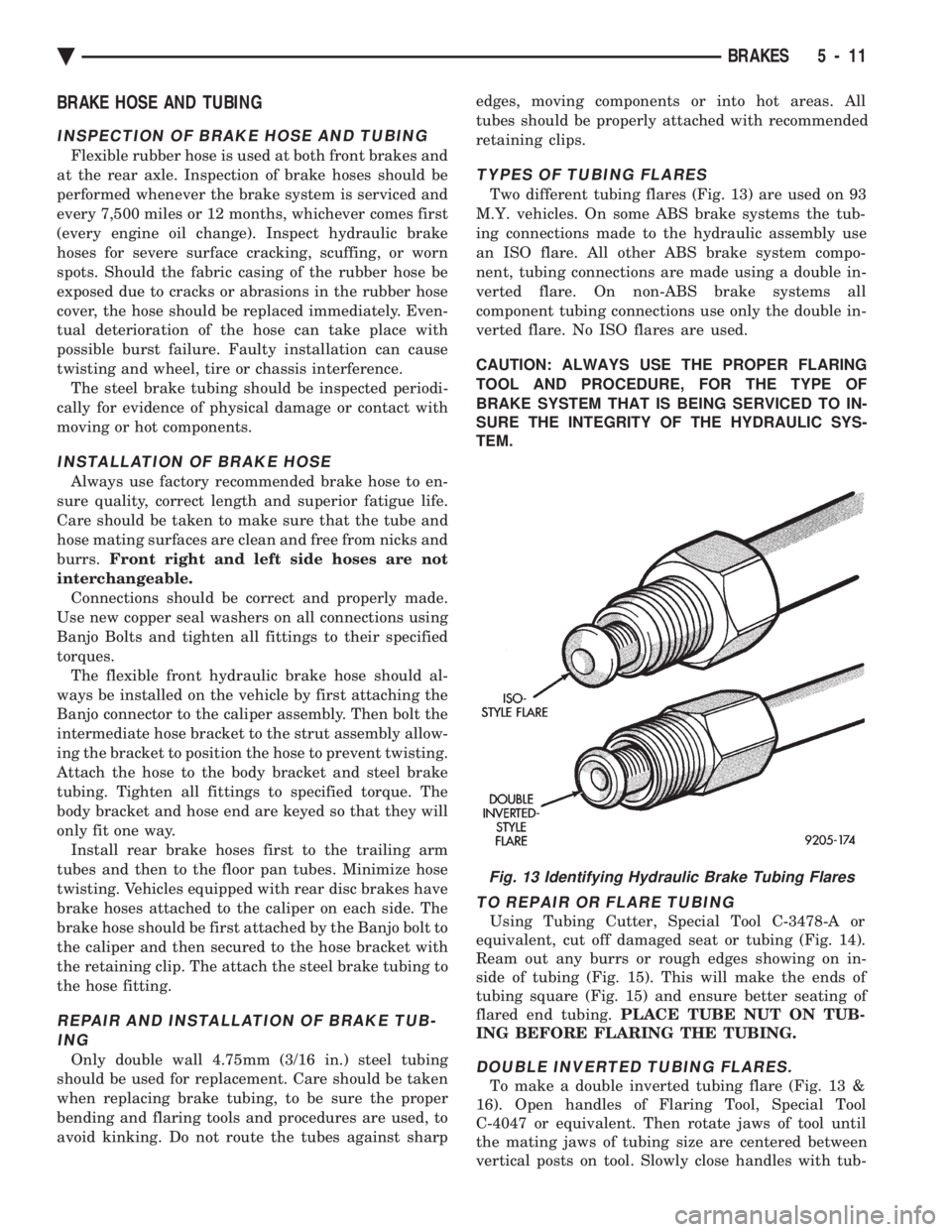
Two different tubing flares (Fig. 13) are used on 93
M.Y. vehicles. On some ABS brake systems the tub-
ing connections made to the hydraulic assembly use
an ISO flare. All other ABS brake system compo-
nent, tubing connections are made using a double in-
verted flare. On non-ABS brake systems all
component tubing connections use only the double in-
verted flare. No ISO flares are used.
CAUTION: ALWAYS USE THE PROPER FLARING
TOOL AND PROCEDURE, FOR THE TYPE OF
BRAKE SYSTEM THAT IS BEING SERVICED TO IN-
SURE THE INTEGRITY OF THE HYDRAULIC SYS-
TEM.
TO REPAIR OR FLARE TUBING
Using Tubing Cutter, Special Tool C-3478-A or
equivalent, cut off damaged seat or tubing (Fig. 14).
Ream out any burrs or rough edges showing on in-
side of tubing (Fig. 15). This will make the ends of
tubing square (Fig. 15) and ensure better seating of
flared end tubing. PLACE TUBE NUT ON TUB-
ING BEFORE FLARING THE TUBING.
DOUBLE INVERTED TUBING FLARES.
To make a double inverted tubing flare (Fig. 13 &
16). Open handles of Flaring Tool, Special Tool
C-4047 or equivalent. Then rotate jaws of tool until
the mating jaws of tubing size are centered between
vertical posts on tool. Slowly close handles with tub-
Fig. 13 Identifying Hydraulic Brake Tubing Flares
Ä BRAKES 5 - 11
Page 193 of 2438
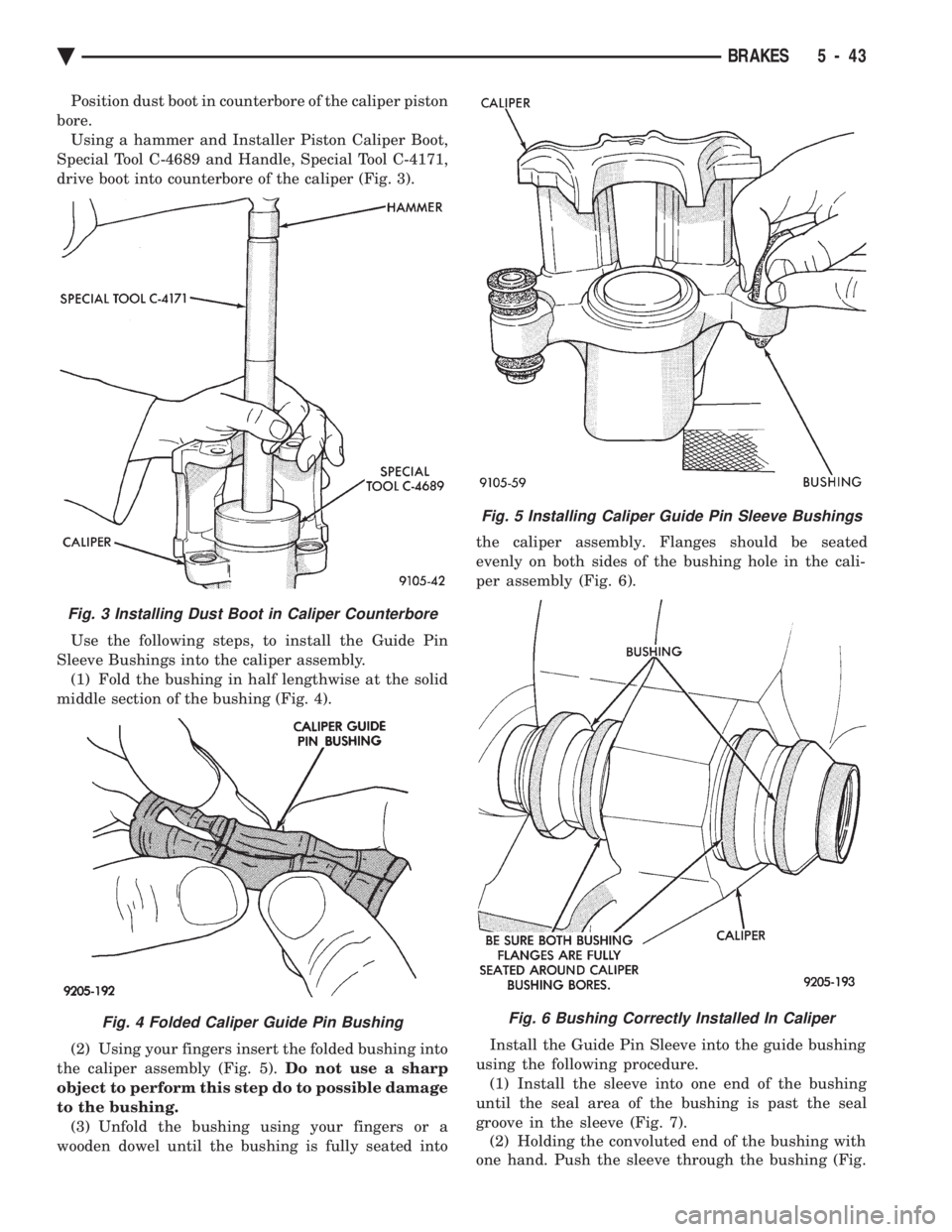
Position dust boot in counterbore of the caliper piston
bore. Using a hammer and Installer Piston Caliper Boot,
Special Tool C-4689 and Handle, Special Tool C-4171,
drive boot into counterbore of the caliper (Fig. 3).
Use the following steps, to install the Guide Pin
Sleeve Bushings into the caliper assembly. (1) Fold the bushing in half lengthwise at the solid
middle section of the bushing (Fig. 4).
(2) Using your fingers insert the folded bushing into
the caliper assembly (Fig. 5). Do not use a sharp
object to perform this step do to possible damage
to the bushing. (3) Unfold the bushing using your fingers or a
wooden dowel until the bushing is fully seated into the caliper assembly. Flanges should be seated
evenly on both sides of the bushing hole in the cali-
per assembly (Fig. 6).
Install the Guide Pin Sleeve into the guide bushing
using the following procedure. (1) Install the sleeve into one end of the bushing
until the seal area of the bushing is past the seal
groove in the sleeve (Fig. 7). (2) Holding the convoluted end of the bushing with
one hand. Push the sleeve through the bushing (Fig.
Fig. 5 Installing Caliper Guide Pin Sleeve Bushings
Fig. 6 Bushing Correctly Installed In Caliper
Fig. 3 Installing Dust Boot in Caliper Counterbore
Fig. 4 Folded Caliper Guide Pin Bushing
Ä BRAKES 5 - 43