warning CHEVROLET PLYMOUTH ACCLAIM 1993 Service Manual
[x] Cancel search | Manufacturer: CHEVROLET, Model Year: 1993, Model line: PLYMOUTH ACCLAIM, Model: CHEVROLET PLYMOUTH ACCLAIM 1993Pages: 2438, PDF Size: 74.98 MB
Page 2 of 2438
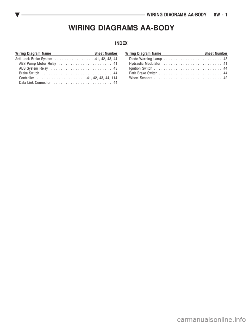
WIRING DIAGRAMS AA-BODY
INDEX
Wiring Diagram Name Sheet Number
Anti-Lock Brake System.................41, 42, 43, 44
ABS Pump Motor Relay.......................41
ABS System Relay..........................43
Brake Switch..............................44
Controller.....................41, 42, 43, 44, 114
Data Link Connector.........................44Wiring Diagram Name Sheet Number
Diode-Warning Lamp.........................43
Hydraulic Modulator.........................41
Ignition Switch.............................44
Park Brake Switch...........................44
Wheel Sensors.............................42
ÄWIRING DIAGRAMS AA-BODY 8W - 1
Page 9 of 2438
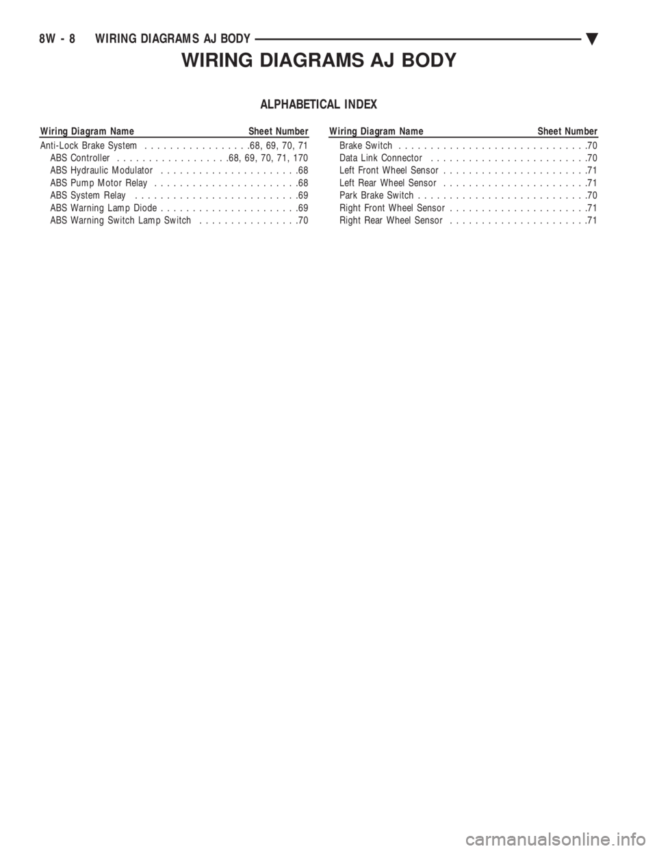
WIRING DIAGRAMS AJ BODY
ALPHABETICAL INDEX
Wiring Diagram Name Sheet Number
Anti-Lock Brake System.................68, 69, 70, 71
ABS Controller..................68, 69, 70, 71, 170
ABS Hydraulic Modulator......................68
ABS Pump Motor Relay.......................68
ABS System Relay..........................69
ABS Warning Lamp Diode......................69
ABS Warning Switch Lamp Switch................70Wiring Diagram Name Sheet Number
Brake Switch..............................70
Data Link Connector.........................70
Left Front Wheel Sensor.......................71
Left Rear Wheel Sensor.......................71
Park Brake Switch...........................70
Right Front Wheel Sensor......................71
Right Rear Wheel Sensor......................71
8W - 8 WIRING DIAGRAMS AJ BODYÄ
Page 22 of 2438
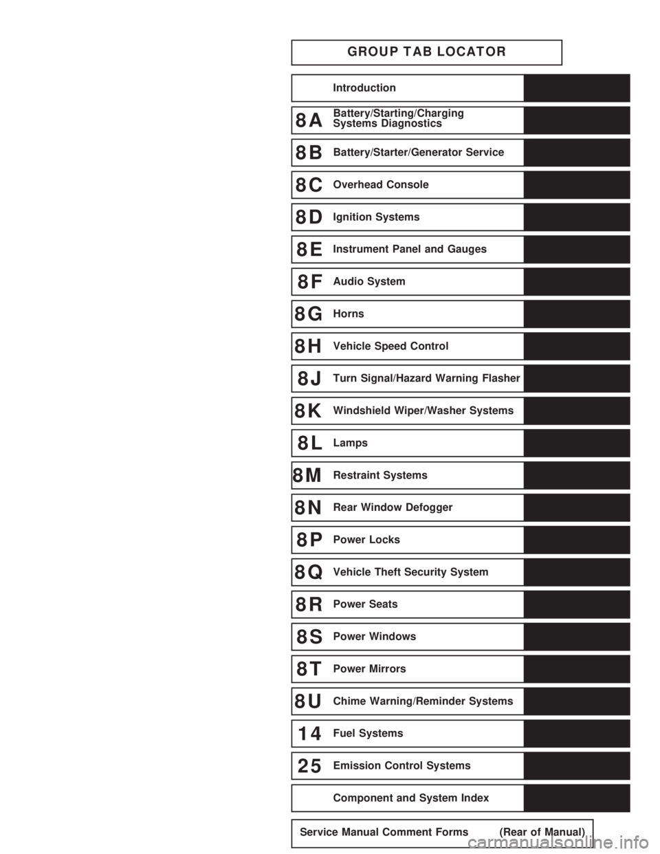
GROUP TAB LOCATOR
Introduction
8ABattery/Starting/Charging
Systems Diagnostics
8BBattery/Starter/Generator Service
8COverhead Console
8DIgnition Systems
8EInstrument Panel and Gauges
8FAudio System
8GHorns
8HVehicle Speed Control
8JTurn Signal/Hazard Warning Flasher
8KWindshield Wiper/Washer Systems
8LLamps
8MRestraint Systems
8NRear Window Defogger
8PPower Locks
8QVehicle Theft Security System
8RPower Seats
8SPower Windows
8TPower Mirrors
8UChime Warning/Reminder Systems
14Fuel Systems
25Emission Control Systems
Component and System Index
Service Manual Comment Forms (Rear of Manual)
Page 33 of 2438
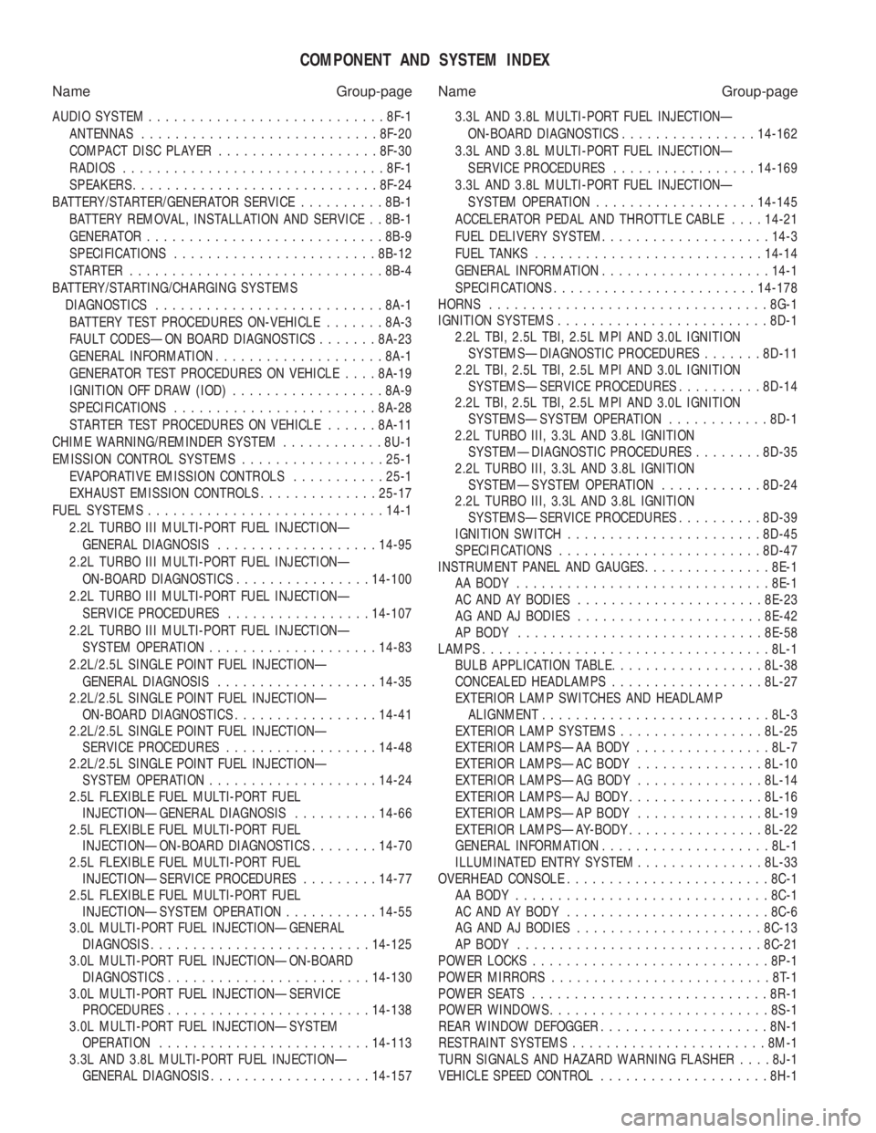
COMPONENT AND SYSTEM INDEX
Name Group-page Name Group-page
AUDIO SYSTEM ............................ 8F-1
ANTENNAS ............................ 8F-20
COMPACT DISC PLAYER ................... 8F-30
RADIOS ............................... 8F-1
SPEAKERS ............................. 8F-24
BATTERY/STARTER/GENERATOR SERVICE ..........8B-1
BATTERY REMOVAL, INSTALLATION AND SERVICE . . 8B-1
GENERATOR ............................ 8B-9
SPECIFICATIONS ........................ 8B-12
STARTER .............................. 8B-4
BATTERY/STARTING/CHARGING SYSTEMS DIAGNOSTICS ........................... 8A-1
BATTERY TEST PROCEDURES ON-VEHICLE .......8A-3
FAULT CODESÐON BOARD DIAGNOSTICS .......8A-23
GENERAL INFORMATION .................... 8A-1
GENERATOR TEST PROCEDURES ON VEHICLE ....8A-19
IGNITION OFF DRAW (IOD) ..................8A-9
SPECIFICATIONS ........................ 8A-28
STARTER TEST PROCEDURES ON VEHICLE ......8A-11
CHIME WARNING/REMINDER SYSTEM ............8U-1
EMISSION CONTROL SYSTEMS .................25-1
EVAPORATIVE EMISSION CONTROLS ...........25-1
EXHAUST EMISSION CONTROLS ..............25-17
FUEL SYSTEMS ............................ 14-1
2.2L TURBO III MULTI-PORT FUEL INJECTIONÐ GENERAL DIAGNOSIS ................... 14-95
2.2L TURBO III MULTI-PORT FUEL INJECTIONÐ ON-BOARD DIAGNOSTICS ................14-100
2.2L TURBO III MULTI-PORT FUEL INJECTIONÐ SERVICE PROCEDURES .................14-107
2.2L TURBO III MULTI-PORT FUEL INJECTIONÐ SYSTEM OPERATION .................... 14-83
2.2L/2.5L SINGLE POINT FUEL INJECTIONÐ GENERAL DIAGNOSIS ................... 14-35
2.2L/2.5L SINGLE POINT FUEL INJECTIONÐ ON-BOARD DIAGNOSTICS .................14-41
2.2L/2.5L SINGLE POINT FUEL INJECTIONÐ SERVICE PROCEDURES .................. 14-48
2.2L/2.5L SINGLE POINT FUEL INJECTIONÐ SYSTEM OPERATION .................... 14-24
2.5L FLEXIBLE FUEL MULTI-PORT FUEL INJECTIONÐGENERAL DIAGNOSIS ..........14-66
2.5L FLEXIBLE FUEL MULTI-PORT FUEL INJECTIONÐON-BOARD DIAGNOSTICS ........14-70
2.5L FLEXIBLE FUEL MULTI-PORT FUEL INJECTIONÐSERVICE PROCEDURES .........14-77
2.5L FLEXIBLE FUEL MULTI-PORT FUEL INJECTIONÐSYSTEM OPERATION ...........14-55
3.0L MULTI-PORT FUEL INJECTIONÐGENERAL DIAGNOSIS .......................... 14-125
3.0L MULTI-PORT FUEL INJECTIONÐON-BOARD DIAGNOSTICS ........................ 14-130
3.0L MULTI-PORT FUEL INJECTIONÐSERVICE PROCEDURES ........................ 14-138
3.0L MULTI-PORT FUEL INJECTIONÐSYSTEM OPERATION ......................... 14-113
3.3L AND 3.8L MULTI-PORT FUEL INJECTIONÐ GENERAL DIAGNOSIS ................... 14-157 3.3L AND 3.8L MULTI-PORT FUEL INJECTIONÐ
ON-BOARD DIAGNOSTICS ................14-162
3.3L AND 3.8L MULTI-PORT FUEL INJECTIONÐ SERVICE PROCEDURES .................14-169
3.3L AND 3.8L MULTI-PORT FUEL INJECTIONÐ SYSTEM OPERATION ................... 14-145
ACCELERATOR PEDAL AND THROTTLE CABLE ....14-21
FUEL DELIVERY SYSTEM .................... 14-3
FUEL TANKS ........................... 14-14
GENERAL INFORMATION .................... 14-1
SPECIFICATIONS ........................ 14-178
HORNS ................................. 8G-1
IGNITION SYSTEMS ......................... 8D-1
2.2L TBI, 2.5L TBI, 2.5L MPI AND 3.0L IGNITION SYSTEMSÐDIAGNOSTIC PROCEDURES .......8D-11
2.2L TBI, 2.5L TBI, 2.5L MPI AND 3.0L IGNITION SYSTEMSÐSERVICE PROCEDURES ..........8D-14
2.2L TBI, 2.5L TBI, 2.5L MPI AND 3.0L IGNITION SYSTEMSÐSYSTEM OPERATION ............8D-1
2.2L TURBO III, 3.3L AND 3.8L IGNITION SYSTEMÐDIAGNOSTIC PROCEDURES ........8D-35
2.2L TURBO III, 3.3L AND 3.8L IGNITION SYSTEMÐSYSTEM OPERATION ............8D-24
2.2L TURBO III, 3.3L AND 3.8L IGNITION SYSTEMSÐSERVICE PROCEDURES ..........8D-39
IGNITION SWITCH ....................... 8D-45
SPECIFICATIONS ........................ 8D-47
INSTRUMENT PANEL AND GAUGES ...............8E-1
AA BODY .............................. 8E-1
AC AND AY BODIES ...................... 8E-23
AG AND AJ BODIES ...................... 8E-42
AP BODY ............................. 8E-58
LAMPS .................................. 8L-1
BULB APPLICATION TABLE ..................8L-38
CONCEALED HEADLAMPS ..................8L-27
EXTERIOR LAMP SWITCHES AND HEADLAMP ALIGNMENT ........................... 8L-3
EXTERIOR LAMP SYSTEMS .................8L-25
EXTERIOR LAMPSÐAA BODY ................8L-7
EXTERIOR LAMPSÐAC BODY ...............8L-10
EXTERIOR LAMPSÐAG BODY ...............8L-14
EXTERIOR LAMPSÐAJ BODY ................8L-16
EXTERIOR LAMPSÐAP BODY ...............8L-19
EXTERIOR LAMPSÐAY-BODY ................8L-22
GENERAL INFORMATION .................... 8L-1
ILLUMINATED ENTRY SYSTEM ...............8L-33
OVERHEAD CONSOLE ........................ 8C-1
AA BODY .............................. 8C-1
AC AND AY BODY ........................ 8C-6
AG AND AJ BODIES ...................... 8C-13
AP BODY ............................. 8C-21
POWER LOCKS ............................ 8P-1
POWER MIRRORS ..........................8T-1
POWER SEATS ............................ 8R-1
POWER WINDOWS .......................... 8S-1
REAR WINDOW DEFOGGER .................... 8N-1
RESTRAINT SYSTEMS ....................... 8M-1
TURN SIGNALS AND HAZARD WARNING FLASHER ....8J-1
VEHICLE SPEED CONTROL .................... 8H-1
Page 35 of 2438
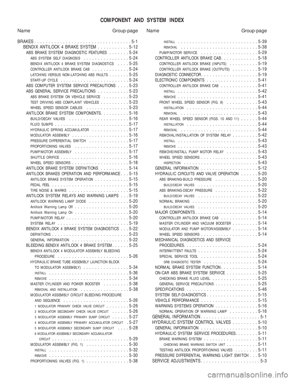
COMPONENT AND SYSTEM INDEX
Name Group-page Name Group-page
BRAKES ..................................5-1
BENDIX ANTILOCK 4 BRAKE SYSTEM ...........5-12
ABS BRAKE SYSTEM DIAGNOSTIC FEATURES.......5-24
ABS SYSTEM SELF DIAGNOSIS................ 5-24
BENDIX ANTILOCK 4 BRAKE SYSTEM DIAGNOSTICS....5-25
CONTROLLER ANTILOCK BRAKE CAB............. 5-24
LATCHING VERSUS NON-LATCHING ABS FAULTS.......5-25
START-UP CYCLE........................ 5-24
ABS COMPUTER SYSTEM SERVICE PRECAUTIONS....5-23
ABS GENERAL SERVICE PRECAUTIONS........... 5-23
ABS BRAKE SYSTEM ON VEHICLE SERVICE.........5-23
TEST DRIVING ABS COMPLAINT VEHICLES.......... 5-23
WHEEL SPEED SENSOR CABLES............... 5-23
ANTILOCK BRAKE SYSTEM COMPONENTS..........5-16
BUILD/DECAY VALVES..................... 5-16
FLUID SUMPS.......................... 5-17
HYDRAULIC SPRING ACCUMULATOR.............5-17
MODULATOR ASSEMBLY.................... 5-16
PRESSURE DIFFERENTIAL SWITCH..............5-17
PROPORTIONING VALVES................... 5-17
PUMP/MOTOR ASSEMBLY...................5-17
SHUTTLE ORIFICE........................ 5-16
WHEEL SPEED SENSORS....................5-18
ANTILOCK BRAKE SYSTEM DEFINITIONS..........5-14
ANTILOCK BRAKES OPERATION AND PERFORMANCE. . . 5-15
ANTILOCK BRAKE SYSTEM OPERATION............ 5-15
PEDAL FEEL........................... 5-15
TIRE NOISE & MARKS.....................5-15
ANTILOCK SYSTEM RELAYS AND WARNING LAMPS. . . 5-19
ANTILOCK WARNING LAMP DIODE..............5-20
Antilock Warning Lamp Off................... 5-20
Antilock Warning Lamp On...................5-20
PUMP/MOTOR RELAY...................... 5-20
SYSTEM RELAY......................... 5-19
BENDIX ANTILOCK 4 BRAKE SYSTEM DIAGNOSTICS. . . 5-22
DEFINITIONS........................... 5-23
GENERAL INFORMATION....................5-22
BLEEDING BENDIX ANTILOCK 4 BRAKE SYSTEM......5-25
BENDIX ANTILOCK 4 MODULATOR ASSEMBLY BLEEDING
PROCEDURE
......................... 5-26
HYDRAULIC BRAKE TUBE ASSEMBLY (JUNCTION BLOCK
TO MODULATOR ASSEMBLY)
................ 5-34
INSTALL............................ 5-36
REMOVE............................5-34
MASTER CYLINDER AND POWER BOOSTER.........5-38
REMOVAL AND INSTALLATION................. 5-38
MODULATOR ASSEMBLY CIRCUIT BLEEDING PROCEDURE
AND SEQUENCE
....................... 5-26
1 MODULATOR PRIMARY CHECK VALVE CIRCUIT........5-26
2 MODULATOR SECONDARY CHECK VALVE CIRCUIT......5-26
3 MODULATOR ASSEMBLY PRIMARY SUMP CIRCUIT......5-27
4 MODULATOR ASSEMBLY PRIMARY ACCUMULATOR CIRCUIT. 5-27
5 MODULATOR ASSEMBLY SECONDARY SUMP CIRCUIT....5-28
6 MODULATOR ASSEMBLY SECONDARY ACCUMULATOR
CIRCUIT
........................... 5-29
MODULATOR ASSEMBLY (FIG. 1)...............5-30
INSTALL............................ 5-32
REMOVE............................5-30
PROPORTIONING VALVES (FIG. 1)...............5-38
INSTALL............................ 5-39
REMOVAL...........................5-38
PUMP/MOTOR SERVICE....................5-29
CONTROLLER ANTILOCK BRAKE CAB.............5-18
CONTROLLER ANTILOCK BRAKE (INPUTS)..........5-19
CONTROLLER ANTILOCK BRAKE (OUTPUTS).........5-19
DIAGNOSTIC CONNECTOR.................... 5-19
ELECTRONIC COMPONENTS..................5-41
CONTROLLER ANTILOCK BRAKE CAB.............5-41
INSTALL............................ 5-42
REMOVE............................5-41
FRONT WHEEL SPEED SENSOR (FIG. 9)...........5-43
INSTALLATION......................... 5-44
REMOVAL........................... 5-43
REAR WHEEL SPEED SENSOR (FIGS. 10 AND 11)......5-44
INSTALLATION......................... 5-44
REMOVAL........................... 5-44
REMOVAL/INSTALLATION OF SYSTEM RELAY.........5-42
INSTALL............................ 5-43
REMOVE............................5-43
REMOVE/INSTALL PUMP MOTOR RELAY...........5-43
WHEEL SPEED SENSORS.................... 5-43
INSPECTION.......................... 5-43
GENERAL INFORMATION....................5-12
HYDRAULIC CIRCUITS AND VALVE OPERATION......5-20
ABS BRAKING-BUILD PRESSURE............... 5-20
BUILD/DECAY VALVES..................... 5-20
ABS BRAKING-DECAY PRESSURE...............5-22
BUILD/DECAY VALVES..................... 5-22
NORMAL BRAKING....................... 5-20
BUILD/DECAY VALVES.....................5-20
MAJOR COMPONENTS...................... 5-14
CONTROLLER ANTILOCK BRAKE CAB.............5-14
MASTER CYLINDER AND VACUUM BOOSTER.........5-14
MODULATOR AND PUMP MOTOR/ASSEMBLY.........5-14
WHEEL SPEED SENSORS.................... 5-14
MECHANICAL DIAGNOSTICS AND SERVICE
PROCEDURES
.......................... 5-24
INTERMITTENT FAULTS.....................5-24
SPECIAL SERVICE TOOL....................5-24
DRB DIAGNOSTIC TESTER...................5-24
NORMAL BRAKE SYSTEM FUNCTION.............5-14
ON-CAR ABS BRAKE SYSTEM SERVICE...........5-25
CHECKING BRAKE FLUID LEVEL................ 5-25
GENERAL SERVICE PRECAUTIONS...............5-25
SPECIFICATIONS......................... 5-46
SYSTEM SELF-DIAGNOSTICS..................5-15
VEHICLE PERFORMANCE.................... 5-15
WARNING SYSTEMS OPERATION...............5-16
NORMAL OPERATION OF WARNING LAMP..........5-16
GENERAL INFORMATION .....................5-1
HYDRAULIC SYSTEM CONTROL VALVES .........5-10
GENERAL INFORMATION.................... 5-10
HYDRAULIC SYSTEM SERVICE PROCEDURES........5-11
BRAKE WARNING SYSTEM................... 5-11
CHECKING BRAKE WARNING SWITCH UNIT...........5-11
TESTING ANTILOCK PROPORTIONING VALVES........5-11
PRESSURE DIFFERENTIAL WARNING LIGHT SWITCH. . . 5-10
SERVICE ADJUSTMENTS .....................5-3
Page 40 of 2438
LUBRICANTS AND GREASES
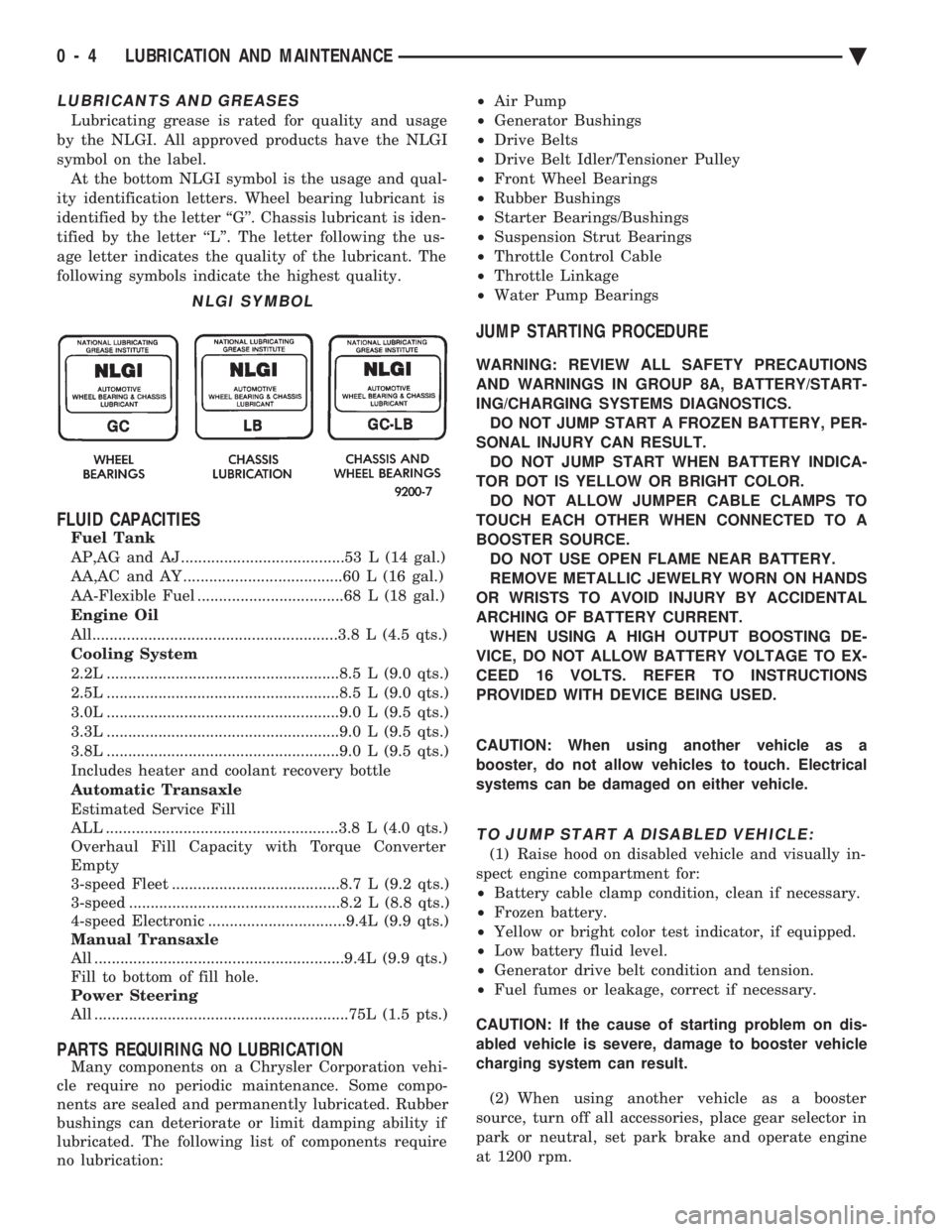
Lubricating grease is rated for quality and usage
by the NLGI. All approved products have the NLGI
symbol on the label. At the bottom NLGI symbol is the usage and qual-
ity identification letters. Wheel bearing lubricant is
identified by the letter ``G''. Chassis lubricant is iden-
tified by the letter ``L''. The letter following the us-
age letter indicates the quality of the lubricant. The
following symbols indicate the highest quality.
FLUID CAPACITIES
Fuel Tank
AP,AG and AJ ......................................53 L (14 gal.)
AA,AC and AY .....................................60 L (16 gal.)
AA-Flexible Fuel ..................................68 L (18 gal.)
Engine Oil
All.........................................................3.8 L (4.5 qts.)
Cooling System
2.2L ......................................................8.5 L (9.0 qts.)
2.5L ......................................................8.5 L (9.0 qts.)
3.0L ......................................................9.0 L (9.5 qts.)
3.3L ......................................................9.0 L (9.5 qts.)
3.8L ......................................................9.0 L (9.5 qts.)
Includes heater and coolant recovery bottle
Automatic Transaxle
Estimated Service Fill
ALL ......................................................3.8 L (4.0 qts.)
Overhaul Fill Capacity with Torque Converter
Empty
3-speed Fleet .......................................8.7 L (9.2 qts.)
3-speed .................................................8.2 L (8.8 qts.)
4-speed Electronic ................................9.4L (9.9 qts.)
Manual Transaxle
All ..........................................................9.4L (9.9 qts.)
Fill to bottom of fill hole.
Power Steering
All ...........................................................75L (1.5 pts.)
PARTS REQUIRING NO LUBRICATION
Many components on a Chrysler Corporation vehi-
cle require no periodic maintenance. Some compo-
nents are sealed and permanently lubricated. Rubber
bushings can deteriorate or limit damping ability if
lubricated. The following list of components require
no lubrication: ²
Air Pump
² Generator Bushings
² Drive Belts
² Drive Belt Idler/Tensioner Pulley
² Front Wheel Bearings
² Rubber Bushings
² Starter Bearings/Bushings
² Suspension Strut Bearings
² Throttle Control Cable
² Throttle Linkage
² Water Pump Bearings
JUMP STARTING PROCEDURE
WARNING: REVIEW ALL SAFETY PRECAUTIONS
AND WARNINGS IN GROUP 8A, BATTERY/START-
ING/CHARGING SYSTEMS DIAGNOSTICS. DO NOT JUMP START A FROZEN BATTERY, PER-
SONAL INJURY CAN RESULT. DO NOT JUMP START WHEN BATTERY INDICA-
TOR DOT IS YELLOW OR BRIGHT COLOR. DO NOT ALLOW JUMPER CABLE CLAMPS TO
TOUCH EACH OTHER WHEN CONNECTED TO A
BOOSTER SOURCE. DO NOT USE OPEN FLAME NEAR BATTERY.
REMOVE METALLIC JEWELRY WORN ON HANDS
OR WRISTS TO AVOID INJURY BY ACCIDENTAL
ARCHING OF BATTERY CURRENT. WHEN USING A HIGH OUTPUT BOOSTING DE-
VICE, DO NOT ALLOW BATTERY VOLTAGE TO EX-
CEED 16 VOLTS. REFER TO INSTRUCTIONS
PROVIDED WITH DEVICE BEING USED.
CAUTION: When using another vehicle as a
booster, do not allow vehicles to touch. Electrical
systems can be damaged on either vehicle.
TO JUMP START A DISABLED VEHICLE:
(1) Raise hood on disabled vehicle and visually in-
spect engine compartment for:
² Battery cable clamp condition, clean if necessary.
² Frozen battery.
² Yellow or bright color test indicator, if equipped.
² Low battery fluid level.
² Generator drive belt condition and tension.
² Fuel fumes or leakage, correct if necessary.
CAUTION: If the cause of starting problem on dis-
abled vehicle is severe, damage to booster vehicle
charging system can result.
(2) When using another vehicle as a booster
source, turn off all accessories, place gear selector in
park or neutral, set park brake and operate engine
at 1200 rpm.
NLGI SYMBOL
0 - 4 LUBRICATION AND MAINTENANCE Ä
Page 41 of 2438
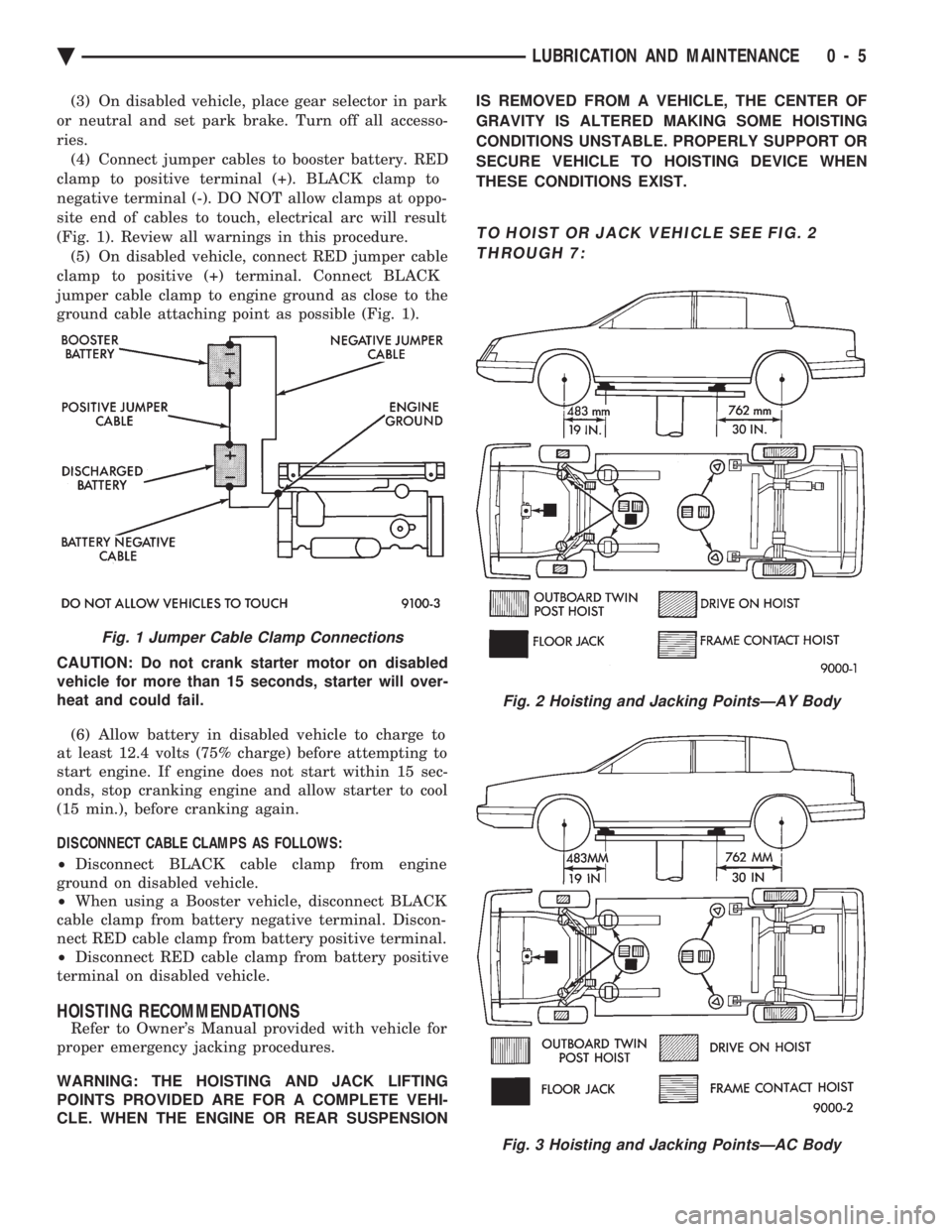
(3) On disabled vehicle, place gear selector in park
or neutral and set park brake. Turn off all accesso-
ries. (4) Connect jumper cables to booster battery. RED
clamp to positive terminal (+). BLACK clamp to
negative terminal (-). DO NOT allow clamps at oppo-
site end of cables to touch, electrical arc will result
(Fig. 1). Review all warnings in this procedure. (5) On disabled vehicle, connect RED jumper cable
clamp to positive (+) terminal. Connect BLACK
jumper cable clamp to engine ground as close to the
ground cable attaching point as possible (Fig. 1).
CAUTION: Do not crank starter motor on disabled
vehicle for more than 15 seconds, starter will over-
heat and could fail.
(6) Allow battery in disabled vehicle to charge to
at least 12.4 volts (75% charge) before attempting to
start engine. If engine does not start within 15 sec-
onds, stop cranking engine and allow starter to cool
(15 min.), before cranking again.
DISCONNECT CABLE CLAMPS AS FOLLOWS:
² Disconnect BLACK cable clamp from engine
ground on disabled vehicle.
² When using a Booster vehicle, disconnect BLACK
cable clamp from battery negative terminal. Discon-
nect RED cable clamp from battery positive terminal.
² Disconnect RED cable clamp from battery positive
terminal on disabled vehicle.
HOISTING RECOMMENDATIONS
Refer to Owner's Manual provided with vehicle for
proper emergency jacking procedures.
WARNING: THE HOISTING AND JACK LIFTING
POINTS PROVIDED ARE FOR A COMPLETE VEHI-
CLE. WHEN THE ENGINE OR REAR SUSPENSION IS REMOVED FROM A VEHICLE, THE CENTER OF
GRAVITY IS ALTERED MAKING SOME HOISTING
CONDITIONS UNSTABLE. PROPERLY SUPPORT OR
SECURE VEHICLE TO HOISTING DEVICE WHEN
THESE CONDITIONS EXIST.
TO HOIST OR JACK VEHICLE SEE FIG. 2 THROUGH 7:
Fig. 1 Jumper Cable Clamp Connections
Fig. 2 Hoisting and Jacking PointsÐAY Body
Fig. 3 Hoisting and Jacking PointsÐAC Body
Ä LUBRICATION AND MAINTENANCE 0 - 5
Page 43 of 2438
TOWING RECOMMENDATIONS
RECOMMENDED TOWING EQUIPMENT
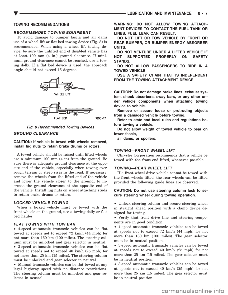
To avoid damage to bumper fascia and air dams
use of a wheel lift or flat bed towing device (Fig. 8) is
recommended. When using a wheel lift towing de-
vice, be sure the unlifted end of disabled vehicle has
at least 100 mm (4 in.) ground clearance. If mini-
mum ground clearance cannot be reached, use a tow-
ing dolly. If a flat bed device is used, the approach
angle should not exceed 15 degrees.
GROUND CLEARANCE
CAUTION: If vehicle is towed with wheels removed,
install lug nuts to retain brake drums or rotors.
A towed vehicle should be raised until lifted wheels
are a minimum 100 mm (4 in) from the ground. Be
sure there is adequate ground clearance at the oppo-
site end of the vehicle, especially when towing over
rough terrain or steep rises in the road. If necessary,
remove the wheels from the lifted end of the vehicle
and lower the vehicle closer to the ground, to in-
crease the ground clearance at the opposite end of
the vehicle. Install lug nuts on wheel attaching studs
to retain brake drums or rotors.
LOCKED VEHICLE TOWING
When a locked vehicle must be towed with the
front wheels on the ground, use a towing dolly or flat
bed hauler.
FLAT TOWING WITH TOW BAR
² 4-speed automatic transaxle vehicles can be flat
towed at speeds not to exceed 72 km/h (44 mph) for
not more than 160 km (100 miles). The steering col-
umn must be unlocked and gear selector in neutral.
² 3-speed automatic transaxle vehicles can be flat
towed at speeds not to exceed 40 km/h (25 mph) for
not more than 25 km (15 miles). The steering column
must be unlocked and gear selector in neutral.
² Manual transaxle vehicles can be flat towed at any
legal highway speed with no distance restrictions.
The steering column must be unlocked and gear se-
lector in neutral. WARNING: DO NOT ALLOW TOWING ATTACH-
MENT DEVICES TO CONTACT THE FUEL TANK OR
LINES, FUEL LEAK CAN RESULT. DO NOT LIFT OR TOW VEHICLE BY FRONT OR
REAR BUMPER, OR BUMPER ENERGY ABSORBER
UNITS. DO NOT VENTURE UNDER A LIFTED VEHICLE IF
NOT SUPPORTED PROPERLY ON SAFETY
STANDS. DO NOT ALLOW PASSENGERS TO RIDE IN A
TOWED VEHICLE. USE A SAFETY CHAIN THAT IS INDEPENDENT
FROM THE TOWING ATTACHMENT DEVICE.
CAUTION: Do not damage brake lines, exhaust sys-
tem, shock absorbers, sway bars, or any other un-
der vehicle components when attaching towing
device to vehicle. Remove or secure loose or protruding objects
from a damaged vehicle before towing. Refer to state and local rules and regulations be-
fore towing a vehicle. Do not allow weight of towed vehicle to bear on
lower fascia, air dams, or spoilers.
TOWINGÐFRONT WHEEL LIFT
Chrysler Corporation recommends that a vehicle be
towed with the front end lifted, whenever possible.
TOWINGÐREAR WHEEL LIFT
If a front wheel drive vehicle cannot be towed with
the front wheels lifted, the rear wheels can be lifted
provided the following guide lines are observed.
CAUTION: Do not use steering column lock to se-
cure steering wheel during towing operation.
² Unlock steering column and secure steering wheel
in straight ahead position with a clamp device de-
signed for towing.
² Verify that front drive line and steering compo-
nents are in good condition.
² 4-speed automatic transaxle vehicles can be towed
at speeds not to exceed 72 km/h (44 mph) for not
more than 160 km (100 miles). The gear selector
must be in neutral position.
² 3-speed automatic transaxle vehicles can be towed
at speeds not to exceed 40 km/h (25 mph) for not
more than 25 km (15 miles). The gear selector must
be in neutral position.
² 3-speed automatic transaxle vehicles can be towed
at speeds not to exceed 40 km/h (25 mph) for not
more than 25 km (15 miles). The gear selector must
be in neutral position.
Fig. 8 Recommended Towing Devices
Ä LUBRICATION AND MAINTENANCE 0 - 7
Page 44 of 2438
ENGINE INDEX
page page
Engine Oil Filter .......................... 9
Battery ................................ 15
Crankcase Ventilation System ............... 13
Drive Belts ............................. 14
Emission Control System ................... 14
Engine Air Cleaner ....................... 11
Engine Cooling System .................... 10 Engine Oil
............................... 8
Frequency of Engine Oil and Filter Changes ..... 8
Fuel Filter .............................. 14
Fuel Recommendations .................... 14
Ignition Cables, Distributor Cap, and Rotor ..... 14
Rubber and Plastic Component Inspection ...... 15
Spark Plugs ............................ 14
FREQUENCY OF ENGINE OIL AND FILTER
CHANGES
ENGINE OIL
Road conditions as well as your kind of driving af-
fect the interval at which your oil should be changed.
Check the following to determine if any apply to you:
² Frequent short trip driving less than 8 kilometers
(5 miles)
² Frequent driving in dusty conditions
² Frequent trailer towing
² Extensive idling (such as vehicle operation in stop
and go traffic)
² More than 50% of your driving is at sustained
high speeds during hot weather, above 32ÉC (90ÉF) If any of these apply to you then change your en-
gine oil every 4 800 kilometers (3,000 miles) or 3
months, whichever comes first. If none of these apply to you then change your oil
every 12 000 kilometers (7,500 miles) or 6 months,
whichever comes first. If none of these apply and the vehicle is in com-
mercial type service such as, Police, Taxi or Limou-
sine and principally used for highway driving of 40
kilometers (25 miles) or more between stations, the
engine oil should be changed every 8 000 kilometers
(5,000 miles) or 6 months, whichever comes first.
FLEXIBLE FUEL VEHICLES
Flexible fuel is corrosive and contributes to engine
oil contamination. When flexible fuel is being used,
the engine oil should be changed every 8 000 kilome-
ters (5,000 miles) or 6 months, whichever comes first.
OIL FILTER
The engine oil filter should be replaced with a new
filter at every second oil change.
ENGINE OIL
WARNING: NEW OR USED ENGINE OIL CAN BE IR-
RITATING TO THE SKIN. AVOID PROLONGED OR
REPEATED SKIN CONTACT WITH ENGINE OIL.
CONTAMINANTS IN USED ENGINE OIL, CAUSED
BY INTERNAL COMBUSTION, CAN BE HAZARDOUS TO YOUR HEALTH. THOROUGHLY WASH EX-
POSED SKIN WITH SOAP AND WATER. DO NOT WASH SKIN WITH GASOLINE, DIESEL
FUEL, THINNER, OR SOLVENTS, HEALTH PROB-
LEMS CAN RESULT. DO NOT POLLUTE, DISPOSE OF USED ENGINE
OIL PROPERLY. CONTACT YOUR DEALER OR
GOVERNMENT AGENCY FOR LOCATION OF COL-
LECTION CENTER IN YOUR AREA.
BREAK-IN PERIOD
CAUTION: Wide open throttle operation in low
gears, before engine break-in period is complete,
can damage engine.
On a Chrysler Corporation vehicle an extended
break-in period is not required. Driving speeds of not
over 80-90 km/h (50-55 mph) for the first 100 km (60
miles) is recommended. Hard acceleration and high
engine rpm in lower gears should be avoided.
SELECTING ENGINE OIL
CAUTION: Do not use non-detergent or straight
mineral oil when adding or changing crankcase lu-
bricant. Engine or Turbocharger failure can result.
The factory fill engine oil is a high quality, energy
conserving, crankcase lubricant. The Recommended
SAE Viscosity Grades chart defines the viscosity
grades that must be used based on temperature in
the region where vehicle is operated and optional
equipment.
NON-FLEXIBLE FUEL VEHICLES Chrysler Corporation recommends that Mopar mo-
tor oil, or equivalent, be used when adding or chang-
ing crankcase lubricant. The API symbol (Fig. 1) on
the container indicates the viscosity grade, quality
and fuel economy ratings of the lubricant it contains.
Use ENERGY CONSERVING II motor oil with API
SERVICE SG or SG/CD classification.
0 - 8 LUBRICATION AND MAINTENANCE Ä
Page 46 of 2438
ENGINE COOLING SYSTEM
WARNINGS AND PRECAUTIONS
WARNING: ANTIFREEZE IS AN ETHYLENE GLYCOL
BASE COOLANT AND IS HARMFUL IF SWAL-
LOWED OR INHALED. IF SWALLOWED, DRINK
TWO GLASSES OF WATER AND INDUCE VOMIT-
ING. IF INHALED, MOVE TO FRESH AIR AREA.
SEEK MEDICAL ATTENTION IMMEDIATELY. DO
NOT STORE IN OPEN OR UNMARKED CONTAIN-
ERS. WASH SKIN AND CLOTHING THOROUGHLY
AFTER COMING IN CONTACT WITH ETHYLENE
GLYCOL. KEEP OUT OF REACH OF CHILDREN. DISPOSE OF GLYCOL BASE COOLANT PROP-
ERLY, CONTACT YOUR DEALER OR GOVERNMENT
AGENCY FOR LOCATION OF COLLECTION CEN-
TER IN YOUR AREA. DO NOT OPEN A COOLING SYSTEM WHEN THE
ENGINE IS AT RUNNING TEMPERATURE, PER-
SONAL INJURY CAN RESULT. AVOID RADIATOR COOLING FAN WHEN ENGINE
COMPARTMENT RELATED SERVICE IS PER-
FORMED, PERSONAL INJURY CAN RESULT.
CAUTION: Do not use straight antifreeze as engine
coolant, inadequate engine running temperatures
can result. Do not operate vehicle without proper concentra-
tion of recommended ethylene glycol coolant, high
running temperatures and cooling system corrosion
can result.
The engine cooling system will develop internal
pressure of 97 to 123 kPa (14 to 18 psi) at normal op-
erating temperature. Allow the vehicle approxi-
mately one half hour to cool off before opening the
cooling system. As an indicator of pressure, squeeze
the upper radiator hose between index finger and
thumb. If it collapses with little effort the system
would have low internal pressure and should be safe
to open to the first safety notch of the radiator cap.
Refer to Group 7, Cooling System.
COOLING SYSTEM INSPECTION
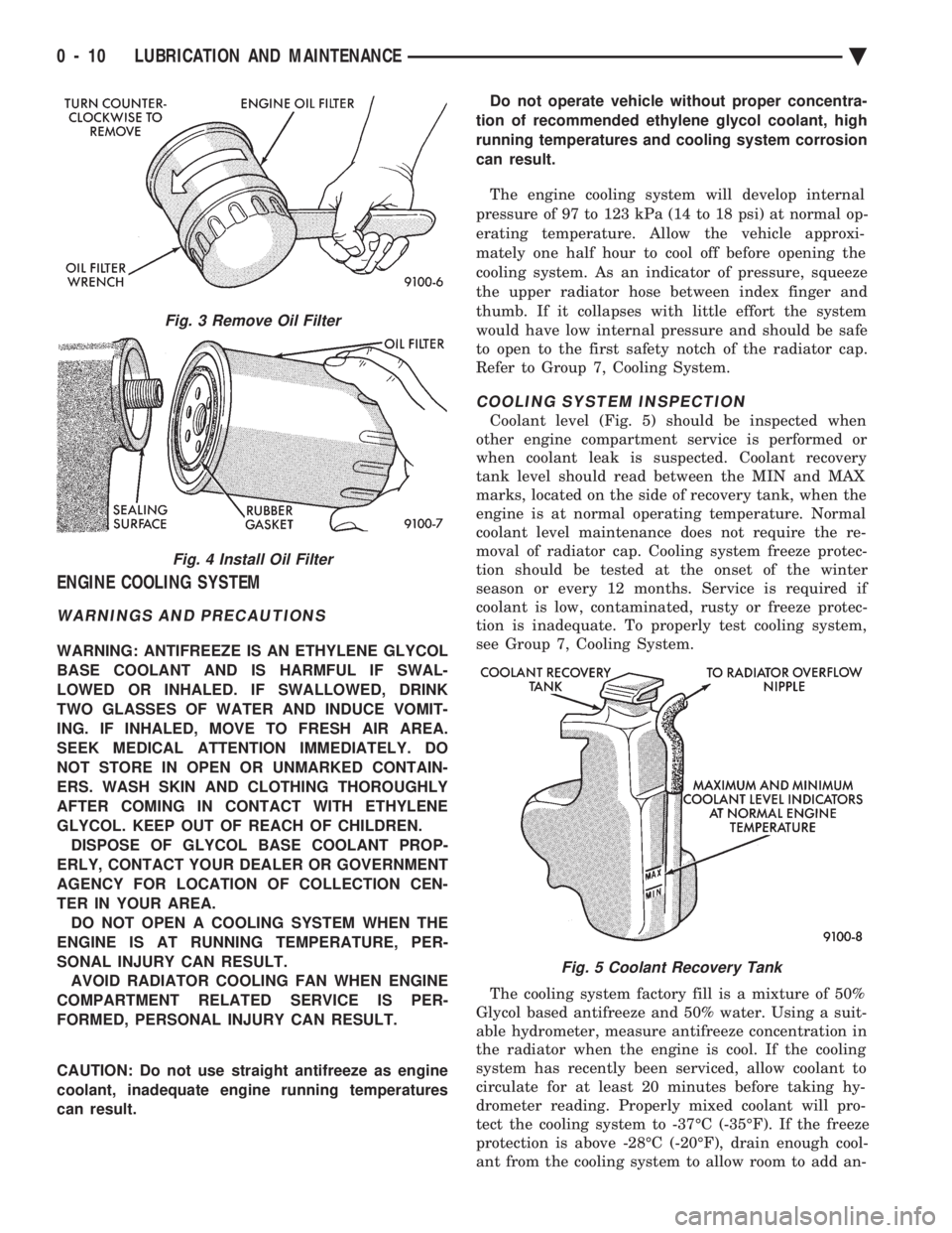
Coolant level (Fig. 5) should be inspected when
other engine compartment service is performed or
when coolant leak is suspected. Coolant recovery
tank level should read between the MIN and MAX
marks, located on the side of recovery tank, when the
engine is at normal operating temperature. Normal
coolant level maintenance does not require the re-
moval of radiator cap. Cooling system freeze protec-
tion should be tested at the onset of the winter
season or every 12 months. Service is required if
coolant is low, contaminated, rusty or freeze protec-
tion is inadequate. To properly test cooling system,
see Group 7, Cooling System.
The cooling system factory fill is a mixture of 50%
Glycol based antifreeze and 50% water. Using a suit-
able hydrometer, measure antifreeze concentration in
the radiator when the engine is cool. If the cooling
system has recently been serviced, allow coolant to
circulate for at least 20 minutes before taking hy-
drometer reading. Properly mixed coolant will pro-
tect the cooling system to -37ÉC (-35ÉF). If the freeze
protection is above -28ÉC (-20ÉF), drain enough cool-
ant from the cooling system to allow room to add an-
Fig. 3 Remove Oil Filter
Fig. 4 Install Oil Filter
Fig. 5 Coolant Recovery Tank
0 - 10 LUBRICATION AND MAINTENANCE Ä