wheel bolts CHEVROLET PLYMOUTH ACCLAIM 1993 Service Manual
[x] Cancel search | Manufacturer: CHEVROLET, Model Year: 1993, Model line: PLYMOUTH ACCLAIM, Model: CHEVROLET PLYMOUTH ACCLAIM 1993Pages: 2438, PDF Size: 74.98 MB
Page 60 of 2438
FRONT SUSPENSION
FRONT SUSPENSION MAJOR COMPONENTS (FIG. 2)
STRUT SUPPORT
The system is supported by coil springs positioned
offset around the struts. The springs are contained
between an upper seat, located just below the top
strut mount assembly (Fig. 2) and a lower spring
seat on the strut lower housing. The top of each strut assembly is bolted to the up-
per fender reinforcement (shock tower) through a
rubber isolated mount. The bottom attaches to the top of the steering
knuckle with two through bolts. On some vehicles,
one bolt has an eccentric cam located below the head
of the bolt for camber adjustment. On the other ve-
hicles the camber adjustment is done by manually
moving the steering knuckle within the strut assem-
bly. Caster is a fixed setting on all vehicles and is
not adjustable.
STEERING KNUCKLE
The steering knuckle is a single casting with legs
machined for attachment to the strut damper, steer-
ing linkage, brake adaptor, and lower control arm
ball joint. The knuckle also holds the front drive hub
bearing. The hub is positioned through the bearing
and knuckle, with the constant velocity stub shaft
splined through the hub.
LOWER CONTROL ARM
The lower control arm is a steel casting with 2
large spool type rubber pivot bushings. The lower
control arm is bolted to the crossmember with pivot
bolts through the center of the rubber pivot bush-
ings. The ball joint is pressed into the control arm and
has a non-tapered stud with a notch for clamp bolt
clearance. The stud is clamped and locked into the
steering knuckle leg with a clamp bolt. The lower control arms are inter-connected through
a rubber isolated sway bar (Fig. 2).
DRIVESHAFTS
A left and right driveshaft is attached inboard to
the transaxle differential side gears, and outboard to
the driven wheel hub. To deliver driving force from the transaxle to the
front wheels during turning maneuvers and suspen-
sion movement. Both shafts are constructed with con-
stant velocity universal joints at both ends. Both shafts have a Tripod (sliding) joint at the
transaxle end and Rzeppa joints (with splined stub
shafts) on the hub ends. Due to the transaxle loca-
tion the connecting shafts between the C/V joints are
of different length and construction. The right shaft
is longer and of tubular construction. The left shaft
is solid.
2 - 2 SUSPENSION AND DRIVESHAFTS Ä
Page 65 of 2438
WHEEL ALIGNMENT SERVICE PROCEDURE
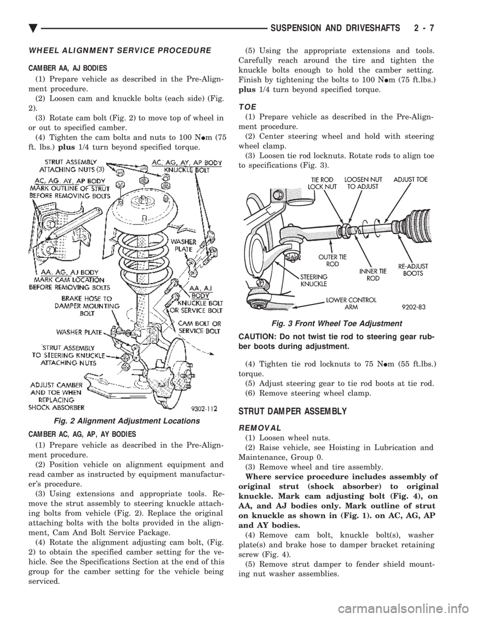
CAMBER AA, AJ BODIES (1) Prepare vehicle as described in the Pre-Align-
ment procedure. (2) Loosen cam and knuckle bolts (each side) (Fig.
2). (3) Rotate cam bolt (Fig. 2) to move top of wheel in
or out to specified camber. (4) Tighten the cam bolts and nuts to 100 N Im (75
ft. lbs.) plus1/4 turn beyond specified torque.
CAMBER AC, AG, AP, AY BODIES (1) Prepare vehicle as described in the Pre-Align-
ment procedure. (2) Position vehicle on alignment equipment and
read camber as instructed by equipment manufactur-
er's procedure. (3) Using extensions and appropriate tools. Re-
move the strut assembly to steering knuckle attach-
ing bolts from vehicle (Fig. 2). Replace the original
attaching bolts with the bolts provided in the align-
ment, Cam And Bolt Service Package. (4) Rotate the alignment adjusting cam bolt, (Fig.
2) to obtain the specified camber setting for the ve-
hicle. See the Specifications Section at the end of this
group for the camber setting for the vehicle being
serviced. (5) Using the appropriate extensions and tools.
Carefully reach around the tire and tighten the
knuckle bolts enough to hold the camber setting.
Finish by tightening the bolts to 100 N Im (75 ft.lbs.)
plus 1/4 turn beyond specified torque.
TOE
(1) Prepare vehicle as described in the Pre-Align-
ment procedure. (2) Center steering wheel and hold with steering
wheel clamp. (3) Loosen tie rod locknuts. Rotate rods to align toe
to specifications (Fig. 3).
CAUTION: Do not twist tie rod to steering gear rub-
ber boots during adjustment. (4) Tighten tie rod locknuts to 75 N Im (55 ft.lbs.)
torque. (5) Adjust steering gear to tie rod boots at tie rod.
(6) Remove steering wheel clamp.
STRUT DAMPER ASSEMBLY
REMOVAL
(1) Loosen wheel nuts.
(2) Raise vehicle, see Hoisting in Lubrication and
Maintenance, Group 0. (3) Remove wheel and tire assembly.
Where service procedure includes assembly of
original strut (shock absorber) to original
knuckle. Mark cam adjusting bolt (Fig. 4), on
AA, and AJ bodies only. Mark outline of strut
on knuckle as shown in (Fig. 1). on AC, AG, AP
and AY bodies. (4) Remove cam bolt, knuckle bolt(s), washer
plate(s) and brake hose to damper bracket retaining
screw (Fig. 4). (5) Remove strut damper to fender shield mount-
ing nut washer assemblies.
Fig. 2 Alignment Adjustment Locations
Fig. 3 Front Wheel Toe Adjustment
Ä SUSPENSION AND DRIVESHAFTS 2 - 7
Page 66 of 2438
INSPECTION
Inspect for evidence of fluid running from the up-
per end of the reservoir. (Actual leakage will be a
stream of fluid running down the side and dripping
off lower end of unit). A slight amount of seepage be-
tween the strut rod and strut shaft seal is not un-
usual and does not affect performance of the strut
assembly.
INSTALLATION
(1) Install unit into fender reinforcement and in-
stall retaining nuts and washer assemblies (Fig. 1).
Tighten the 3 nuts to 27 N Im (20 ft. lbs.) torque.
(2) Position steering knuckle neck into strut as-
sembly. Position washer plate and install cam and
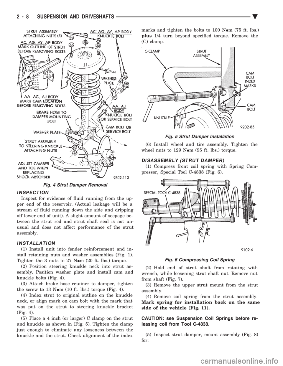
knuckle bolts (Fig. 4). (3) Attach brake hose retainer to damper, tighten
the screw to 13 N Im (10 ft. lbs.) torque (Fig. 4).
(4) Index strut to original outline on the knuckle
neck, or align mark on cam bolt with the mark that
was put on the strut to steering knuckle bracket
(Fig. 4). (5) Plac e a 4 inch (or larger) C clamp on the strut
and knuckle as shown in (Fig. 5). Tighten the clamp
just enough to eliminate any looseness between the
knuckle and the strut. Check alignment of the index marks and tighten the bolts to 100 N
Im (75 ft. lbs.)
plus 1/4 turn beyond specified torque. Remove the
(C) clamp.
(6) Install wheel and tire assembly. Tighten the
wheel nuts to 129 N Im (95 ft. lbs.) torque.
DISASSEMBLY (STRUT DAMPER)
(1) Compress front coil spring with Spring Com-
pressor, Special Tool C-4838 (Fig. 6).
(2) Hold end of strut shaft from rotating with
wrench, while loosening strut shaft nut. Remove nut
from shaft (Fig. 7). (3) Remove the upper strut mount from the strut
assembly. (4) Remove coil spring from the strut assembly.
Mark spring for installation back on the same
side of the vehicle (Fig. 11).
CAUTION: see Suspension Coil Springs before re-
leasing coil from Tool C-4838.
(5) Inspect strut damper, mount assembly (Fig. 8)
for:
Fig. 4 Strut Damper Removal
Fig. 5 Strut Damper Installation
Fig. 6 Compressing Coil Spring
2 - 8 SUSPENSION AND DRIVESHAFTS Ä
Page 74 of 2438
the lower clamps and bolts. The center offset in the
sway bar should be oriented toward the front of the
vehicle (Fig. 16)(3) Position bushing retainers on lower control arms
and install bolts (Fig. 16). (4) With lower control arms raised to design height,
tighten all retainer attaching bolts to 70 N Im (50 ft.
lbs.) torque. (5) Lower vehicle.
KNUCKLE (FRONT SUSPENSION)
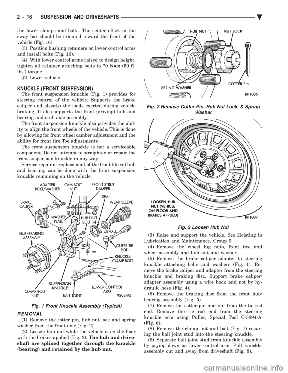
The front suspension knuckle (Fig. 1) provides for
steering control of the vehicle. Supports the brake
caliper and absorbs the loads exerted during vehicle
braking. It also supports the front (driving) hub and
bearing and stub axle assembly. The front suspension knuckle also provides the abil-
ity to align the front wheels of the vehicle. This is done
by allowing for front wheel camber adjustment and the
ability for front tire Toe adjustments The front suspension knuckle is not a serviceable
component. Do not attempt to straighten or repair the
front suspension knuckle in any way. Service repair or replacement of the front (drive) hub
and bearing, can be done with the front suspension
knuckle remaining on the vehicle.
REMOVAL
(1) Remove the cotter pin, hub nut lock and spring
washer from the front axle (Fig. 2). (2) Loosen hub nut while the vehicle is on the floor
with the brakes applied (Fig. 3). The hub and drive-
shaft are splined together through the knuckle
(bearing) and retained by the hub nut. (3) Raise and support the vehicle. See Hoisting in
Lubrication and Maintenance, Group 0. (4) Remove the wheel lug nuts, front tire and
wheel assembly and hub nut and washer. (5) Remove the brake caliper adapter to steering
knuckle attaching bolts and washers (Fig. 1). Re-
move the brake caliper and adapter from the steering
knuckle and braking disc. Support brake caliper/
adapter assembly using a wire hook and not by hy-
draulic hose (Fig. 4). (6) Remove the braking disc from the front hub/
bearing assembly (Fig. 5). (7) Remove the cotter pin and nut from the tie rod
end. Remove the tie rod end from the steering
knuckle arm using Puller, Special Tool C-3894-A
(Fig. 6). (8) Remove the clamp nut and bolt (Fig. 7) secur-
ing the ball joint stud into the steering knuckle. (9) Separate ball joint stud from knuckle assembly
by prying down on lower control arm. Pull knuckle
assembly out and away from driveshaft (Fig. 8).
Fig. 2 Remove Cotter Pin, Hub Nut Lock, & Spring Washer
Fig. 3 Loosen Hub Nut
Fig. 1 Front Knuckle Assembly (Typical)
2 - 16 SUSPENSION AND DRIVESHAFTS Ä
Page 77 of 2438
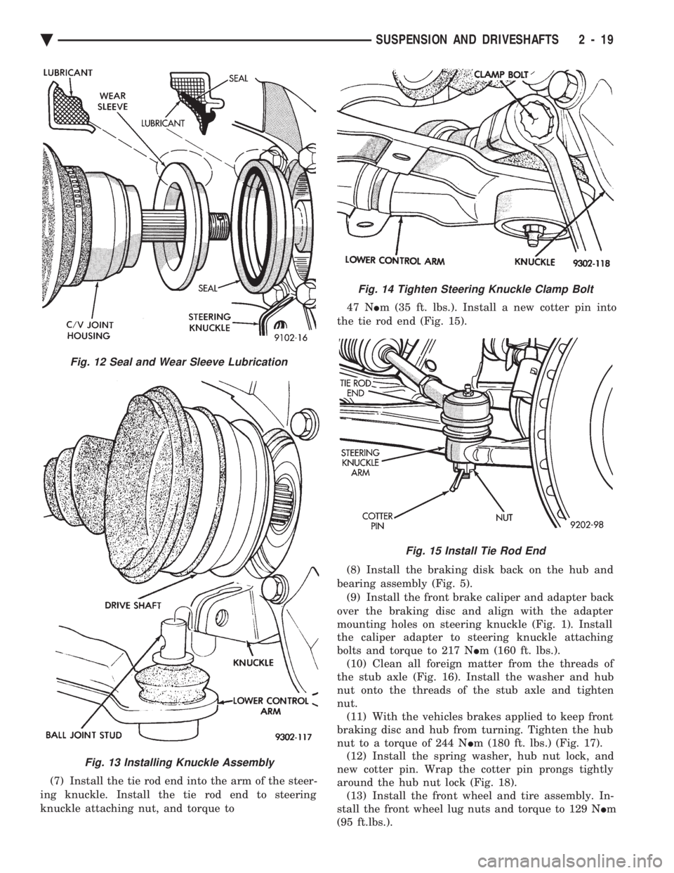
(7) Install the tie rod end into the arm of the steer-
ing knuckle. Install the tie rod end to steering
knuckle attaching nut, and torque to 47 N
Im (35 ft. lbs.). Install a new cotter pin into
the tie rod end (Fig. 15).
(8) Install the braking disk back on the hub and
bearing assembly (Fig. 5). (9) Install the front brake caliper and adapter back
over the braking disc and align with the adapter
mounting holes on steering knuckle (Fig. 1). Install
the caliper adapter to steering knuckle attaching
bolts and torque to 217 N Im (160 ft. lbs.).
(10) Clean all foreign matter from the threads of
the stub axle (Fig. 16). Install the washer and hub
nut onto the threads of the stub axle and tighten
nut. (11) With the vehicles brakes applied to keep front
braking disc and hub from turning. Tighten the hub
nut to a torque of 244 N Im (180 ft. lbs.) (Fig. 17).
(12) Install the spring washer, hub nut lock, and
new cotter pin. Wrap the cotter pin prongs tightly
around the hub nut lock (Fig. 18). (13) Install the front wheel and tire assembly. In-
stall the front wheel lug nuts and torque to 129 N Im
(95 ft.lbs.).
Fig. 13 Installing Knuckle Assembly
Fig. 12 Seal and Wear Sleeve Lubrication
Fig. 14 Tighten Steering Knuckle Clamp Bolt
Fig. 15 Install Tie Rod End
Ä SUSPENSION AND DRIVESHAFTS 2 - 19
Page 78 of 2438
(14) Lower vehicle.
(15) Align the front wheels of the vehicle. Use the
procedure listed under Wheel Alignment, in the
Front Suspension Service Procedures section of this
service manual.
HUB AND BEARING ASSEMBLY
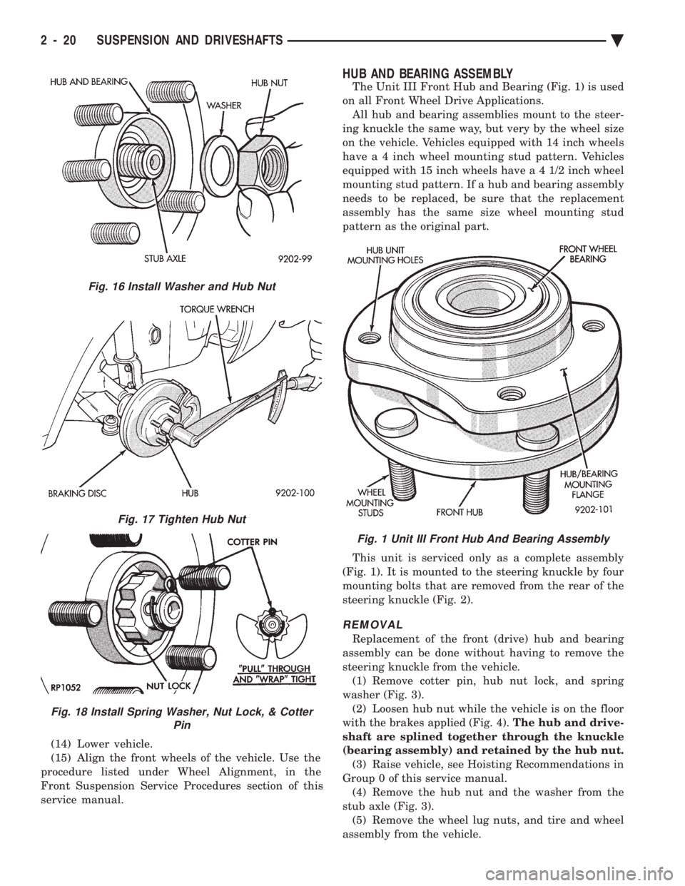
The Unit III Front Hub and Bearing (Fig. 1) is used
on all Front Wheel Drive Applications. All hub and bearing assemblies mount to the steer-
ing knuckle the same way, but very by the wheel size
on the vehicle. Vehicles equipped with 14 inch wheels
have a 4 inch wheel mounting stud pattern. Vehicles
equipped with 15 inch wheels hav e a 4 1/2 inch wheel
mounting stud pattern. If a hub and bearing assembly
needs to be replaced, be sure that the replacement
assembly has the same size wheel mounting stud
pattern as the original part.
This unit is serviced only as a complete assembly
(Fig. 1). It is mounted to the steering knuckle by four
mounting bolts that are removed from the rear of the
steering knuckle (Fig. 2).
REMOVAL
Replacement of the front (drive) hub and bearing
assembly can be done without having to remove the
steering knuckle from the vehicle. (1) Remove cotter pin, hub nut lock, and spring
washer (Fig. 3). (2) Loosen hub nut while the vehicle is on the floor
with the brakes applied (Fig. 4). The hub and drive-
shaft are splined together through the knuckle
(bearing assembly) and retained by the hub nut. (3) Raise vehicle, see Hoisting Recommendations in
Group 0 of this service manual. (4) Remove the hub nut and the washer from the
stub axle (Fig. 3). (5) Remove the wheel lug nuts, and tire and wheel
assembly from the vehicle.
Fig. 16 Install Washer and Hub Nut
Fig. 17 Tighten Hub Nut
Fig. 18 Install Spring Washer, Nut Lock, & Cotter Pin
Fig. 1 Unit III Front Hub And Bearing Assembly
2 - 20 SUSPENSION AND DRIVESHAFTS Ä
Page 106 of 2438
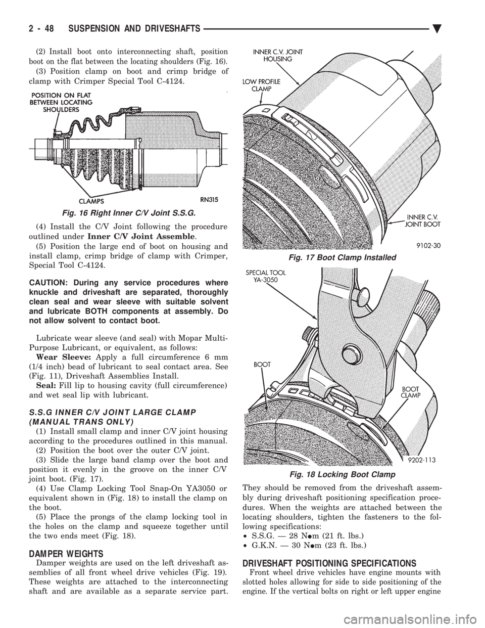
(2) Install boot onto interconnecting shaft, position
boot on the flat between the locating shoulders (Fig. 16).
(3) Position clamp on boot and crimp bridge of
clamp with Crimper Special Tool C-4124.
(4) Install the C/V Joint following the procedure
outlined under Inner C/V Joint Assemble .
(5) Position the large end of boot on housing and
install clamp, crimp bridge of clamp with Crimper,
Special Tool C-4124.
CAUTION: During any service procedures where
knuckle and driveshaft are separated, thoroughly
clean seal and wear sleeve with suitable solvent
and lubricate BOTH components at assembly. Do
not allow solvent to contact boot.
Lubricate wear sleeve (and seal) with Mopar Multi-
Purpose Lubricant, or equivalent, as follows: Wear Sleeve: Apply a full circumference 6 mm
(1/4 inch) bead of lubricant to seal contact area. See
(Fig. 11), Driveshaft Assemblies Install. Seal: Fill lip to housing cavity (full circumference)
and wet seal lip with lubricant.
S.S.G INNER C/V JOINT LARGE CLAMP (MANUAL TRANS ONLY)
(1) Install small clamp and inner C/V joint housing
according to the procedures outlined in this manual. (2) Position the boot over the outer C/V joint.
(3) Slide the large band clamp over the boot and
position it evenly in the groove on the inner C/V
joint boot. (Fig. 17). (4) Use Clamp Locking Tool Snap-On YA3050 or
equivalent shown in (Fig. 18) to install the clamp on
the boot. (5) Place the prongs of the clamp locking tool in
the holes on the clamp and squeeze together until
the two ends meet (Fig. 18).
DAMPER WEIGHTS
Damper weights are used on the left driveshaft as-
semblies of all front wheel drive vehicles (Fig. 19).
These weights are attached to the interconnecting
shaft and are available as a separate service part. They should be removed from the driveshaft assem-
bly during driveshaft positioning specification proce-
dures. When the weights are attached between the
locating shoulders, tighten the fasteners to the fol-
lowing specifications:
² S.S.G. Ð 28 N Im (21 ft. lbs.)
² G.K.N. Ð 30 N Im (23 ft. lbs.)DRIVESHAFT POSITIONING SPECIFICATIONS
Front wheel drive vehicles have engine mounts with
slotted holes allowing for side to side positioning of the
engine. If the vertical bolts on right or left upper engine
Fig. 16 Right Inner C/V Joint S.S.G.
Fig. 17 Boot Clamp Installed
Fig. 18 Locking Boot Clamp
2 - 48 SUSPENSION AND DRIVESHAFTS Ä
Page 109 of 2438
to the road surface. While being able to twist as one
wheel moves vertically with respect to the other.Roll resistance is provided partly by the axle's re-
sistance to twist. But primarily by a torque tube or
rod (depending on the suspension option called for)
running through the channel and attached rigidly to
its end plates by welding. Because the torque tube/
rod is an integral part of the axle assembly, it cannot
be individually replaced. The spindles are bolted to the axle end (spindle
mounting) plates and can be individually replaced if
required. Rear wheel alignment changes require the
use of shims between the spindle and axle end plates.
SHOCK ABSORBERS
REMOVAL
(1) Raise vehicle, see Hoisting, Group 0.
(2) Support axle and remove wheel and tire assem-
bly. (3) If equipped with air shocks, disconnect air
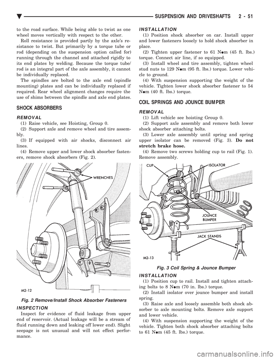
lines. (4) Remove upper and lower shock absorber fasten-
ers, remove shock absorbers (Fig. 2).
INSPECTION
Inspect for evidence of fluid leakage from upper
end of reservoir. (Actual leakage will be a stream of
fluid running down and leaking off lower end). Slight
seepage is not unusual and will not effect perfor-
mance.
INSTALLATION
(1) Position shock absorber on car. Install upper
and lower fasteners loosely to hold shock absorber in
place. (2) Tighten upper fastener to 61 N Im (45 ft. lbs.)
torque. Connect air line, if so equipped. (3) Install wheel and tire assembly, tighten wheel
stud nuts to 129 N Im (95 ft. lbs.) torque. Lower vehi-
cle to ground. (4) With suspension supporting the weight of the
vehicle. Tighten lower shock absorber fastener to 54
N Im (40 ft. lbs.) torque.
COIL SPRINGS AND JOUNCE BUMPER
REMOVAL
(1) Lift vehicle see hoisting Group 0.
(2) Support axle assembly and remove both lower
shock absorber attaching bolts. (3) Lower axle assembly until spring and spring
upper isolator can be removed (Fig. 3). Do not
stretch brake hose. (4) Remove two screws holding cup to rail (Fig. 1).
Remove assembly.
INSTALLATION
(1) Position cup to rail. Install and tighten attach-
ing bolts to 8 N Im (70 in. lbs.) torque.
(2) Install isolator over jounce bumper and install
spring. (3) Raise axle and loosely assemble both shock ab-
sorber to axle mounting bolts. Remove axle support
and lower vehicle. (4) With suspension supporting the weight of the
vehicle. Tighten both shock absorber attaching bolts
to 61 N Im (45 ft. lbs.) torque.
Fig. 2 Remove/Install Shock Absorber Fasteners
Fig. 3 Coil Spring & Jounce Bumper
Ä SUSPENSION AND DRIVESHAFTS 2 - 51
Page 115 of 2438
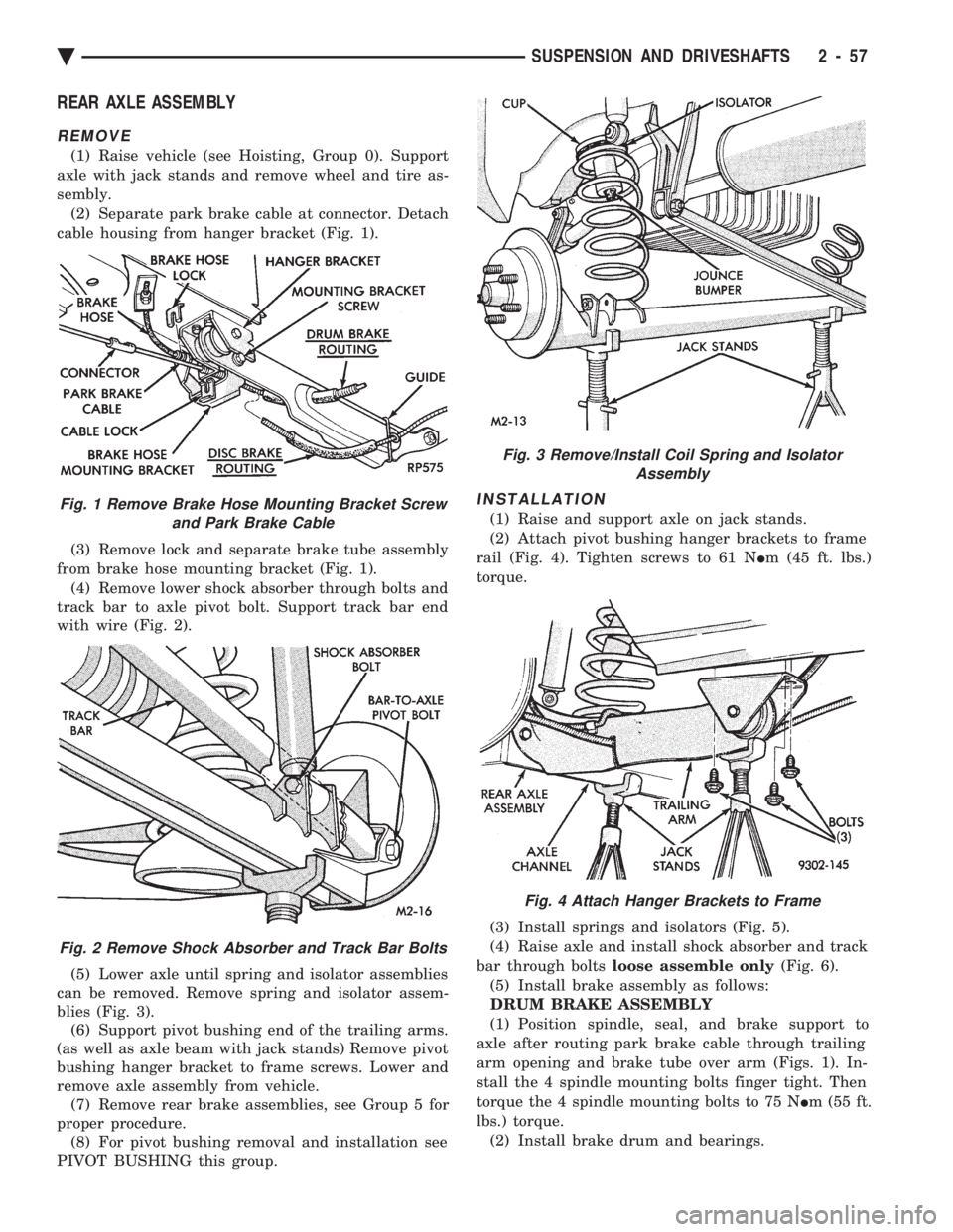
REAR AXLE ASSEMBLY
REMOVE
(1) Raise vehicle (see Hoisting, Group 0). Support
axle with jack stands and remove wheel and tire as-
sembly. (2) Separate park brake cable at connector. Detach
cable housing from hanger bracket (Fig. 1).
(3) Remove lock and separate brake tube assembly
from brake hose mounting bracket (Fig. 1). (4) Remove lower shock absorber through bolts and
track bar to axle pivot bolt. Support track bar end
with wire (Fig. 2).
(5) Lower axle until spring and isolator assemblies
can be removed. Remove spring and isolator assem-
blies (Fig. 3). (6) Support pivot bushing end of the trailing arms.
(as well as axle beam with jack stands) Remove pivot
bushing hanger bracket to frame screws. Lower and
remove axle assembly from vehicle. (7) Remove rear brake assemblies, see Group 5 for
proper procedure. (8) For pivot bushing removal and installation see
PIVOT BUSHING this group.
INSTALLATION
(1) Raise and support axle on jack stands.
(2) Attach pivot bushing hanger brackets to frame
rail (Fig. 4). Tighten screws to 61 N Im (45 ft. lbs.)
torque.
(3) Install springs and isolators (Fig. 5).
(4) Raise axle and install shock absorber and track
bar through bolts loose assemble only (Fig. 6).
(5) Install brake assembly as follows:
DRUM BRAKE ASSEMBLY
(1) Position spindle, seal, and brake support to
axle after routing park brake cable through trailing
arm opening and brake tube over arm (Figs. 1). In-
stall the 4 spindle mounting bolts finger tight. Then
torque the 4 spindle mounting bolts to 75 N Im (55 ft.
lbs.) torque. (2) Install brake drum and bearings.Fig. 1 Remove Brake Hose Mounting Bracket Screw and Park Brake Cable
Fig. 2 Remove Shock Absorber and Track Bar Bolts
Fig. 3 Remove/Install Coil Spring and Isolator Assembly
Fig. 4 Attach Hanger Brackets to Frame
Ä SUSPENSION AND DRIVESHAFTS 2 - 57
Page 116 of 2438
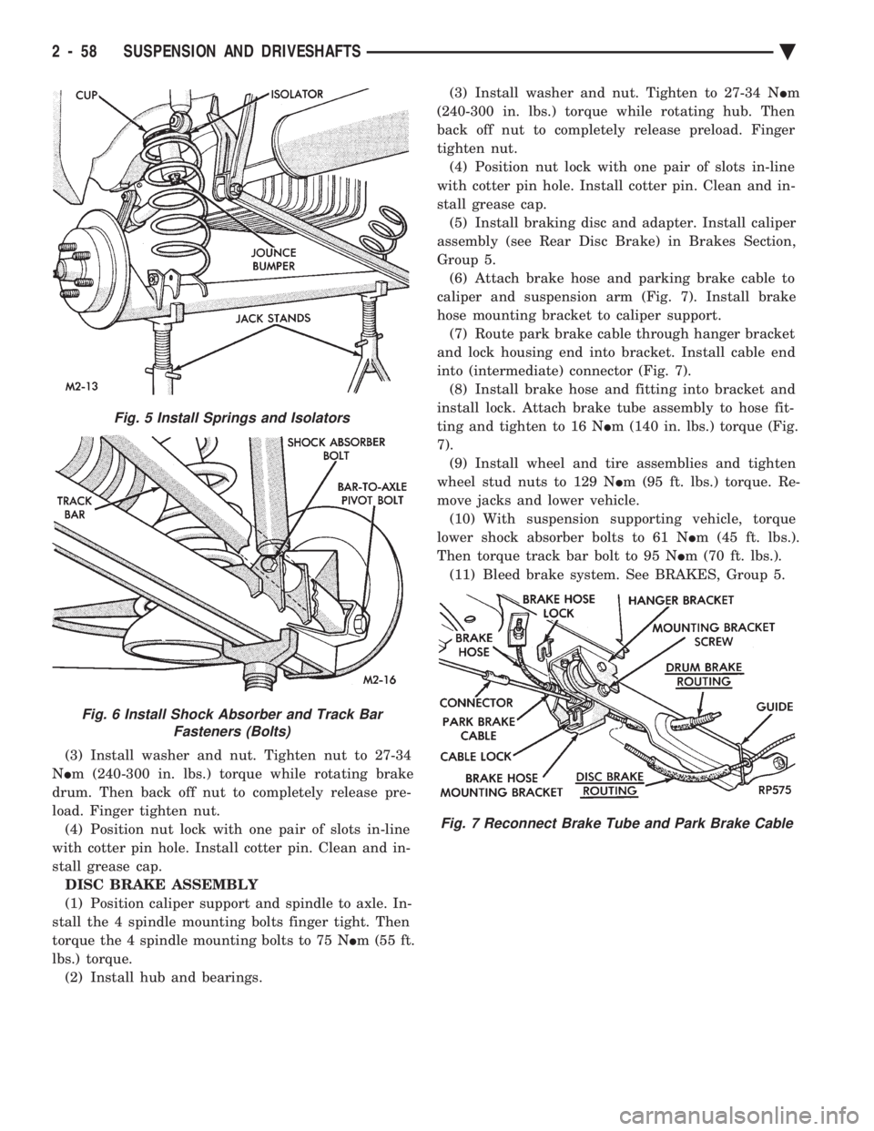
(3) Install washer and nut. Tighten nut to 27-34
N Im (240-300 in. lbs.) torque while rotating brake
drum. Then back off nut to completely release pre-
load. Finger tighten nut. (4) Position nut lock with one pair of slots in-line
with cotter pin hole. Install cotter pin. Clean and in-
stall grease cap. DISC BRAKE ASSEMBLY
(1) Position caliper support and spindle to axle. In-
stall the 4 spindle mounting bolts finger tight. Then
torque the 4 spindle mounting bolts to 75 N Im (55 ft.
lbs.) torque. (2) Install hub and bearings. (3) Install washer and nut. Tighten to 27-34 N
Im
(240-300 in. lbs.) torque while rotating hub. Then
back off nut to completely release preload. Finger
tighten nut. (4) Position nut lock with one pair of slots in-line
with cotter pin hole. Install cotter pin. Clean and in-
stall grease cap. (5) Install braking disc and adapter. Install caliper
assembly (see Rear Disc Brake) in Brakes Section,
Group 5. (6) Attach brake hose and parking brake cable to
caliper and suspension arm (Fig. 7). Install brake
hose mounting bracket to caliper support. (7) Route park brake cable through hanger bracket
and lock housing end into bracket. Install cable end
into (intermediate) connector (Fig. 7). (8) Install brake hose and fitting into bracket and
install lock. Attach brake tube assembly to hose fit-
ting and tighten to 16 N Im (140 in. lbs.) torque (Fig.
7). (9) Install wheel and tire assemblies and tighten
wheel stud nuts to 129 N Im (95 ft. lbs.) torque. Re-
move jacks and lower vehicle. (10) With suspension supporting vehicle, torque
lower shock absorber bolts to 61 N Im (45 ft. lbs.).
Then torque track bar bolt to 95 N Im (70 ft. lbs.).
(11) Bleed brake system. See BRAKES, Group 5.
Fig. 5 Install Springs and Isolators
Fig. 6 Install Shock Absorber and Track Bar Fasteners (Bolts)
Fig. 7 Reconnect Brake Tube and Park Brake Cable
2 - 58 SUSPENSION AND DRIVESHAFTS Ä