wiring CHEVROLET SILVERADO 2009 2.G Owners Manual
[x] Cancel search | Manufacturer: CHEVROLET, Model Year: 2009, Model line: SILVERADO, Model: CHEVROLET SILVERADO 2009 2.GPages: 600, PDF Size: 3.24 MB
Page 96 of 600
Servicing Your Airbag-Equipped
Vehicle
Airbags affect how the vehicle should be serviced.
There are parts of the airbag system in several places
around the vehicle. Your dealer/retailer and the
service manual have information about servicing the
vehicle and the airbag system. To purchase a service
manual, seeService Publications Ordering Information
on page 7-15.
{CAUTION:
For up to 10 seconds after the ignition is turned off
and the battery is disconnected, an airbag can still
in�ate during improper service. You can be injured
if you are close to an airbag when it in�ates. Avoid
yellow connectors. They are probably part of the
airbag system. Be sure to follow proper service
procedures, and make sure the person performing
work for you is quali�ed to do so.
Adding Equipment to Your
Airbag-Equipped Vehicle
Q:Is there anything I might add to or change
about the vehicle that could keep the airbags
from working properly?
A:Yes. If you add things that change your vehicle’s
frame, bumper system, height, front end or side
sheet metal, they may keep the airbag system from
working properly. Changing or moving any parts
of the front seats, safety belts, the airbag sensing
and diagnostic module, steering wheel, instrument
panel, roof-rail airbag modules, ceiling headliner
or pillar garnish trim, overhead console, front
sensors, rollover sensor module, or airbag wiring
can affect the operation of the airbag system.
In addition, your vehicle may have a passenger
sensing system for the right front passenger’s
position, which includes sensors that are part of the
passenger’s seat. The passenger sensing system
may not operate properly if the original seat
trim is replaced with non-GM covers, upholstery or
trim, or with GM covers, upholstery or trim
designed for a different vehicle. Any object, such as
an aftermarket seat heater or a comfort enhancing
pad or device, installed under or on top of the
1-90
Page 97 of 600
seat fabric, could also interfere with the operation of
the passenger sensing system. This could either
prevent proper deployment of the passenger
airbag(s) or prevent the passenger sensing system
from properly turning off the passenger airbag(s).
SeePassenger Sensing System on page 1-85.
If you have any questions about this, you should
contact Customer Assistance before you modify
your vehicle. The phone numbers and addresses for
Customer Assistance are in Step Two of the
Customer Satisfaction Procedure in this manual.
SeeCustomer Satisfaction Procedure on page 7-2.
If your vehicle has rollover roof-rail airbags, see
Different Size Tires and Wheels on page 5-86
for additional important information.
Q:What if I added a snow plow? Will it keep the
airbags from working properly?
A:We have designed our airbag systems to work
properly under a wide range of conditions,
including snow plowing with vehicles that have the
optional Snow Plow Prep Package (RPO VYU).
But do not change or defeat the snow plow’s
“tripping mechanism.” If you do, it can damage your
snow plow and your vehicle, and it may cause an
airbag in�ation.
Q:Because I have a disability, I have to get my
vehicle modi�ed. How can I �nd out whether
this will affect my airbag system?
A:If you have questions, call Customer Assistance.
The phone numbers and addresses for Customer
Assistance are in Step Two of the Customer
Satisfaction Procedure in this manual. See
Customer Satisfaction Procedure on page 7-2.
In addition, your dealer/retailer and the service manual
have information about the location of the airbag
sensors, sensing and diagnostic module and airbag
wiring.
1-91
Page 205 of 600
Puddle Lamps
If the vehicle has puddle lamps, they come on when the
unlock button on the Remote Keyless Entry (RKE)
Transmitter is pressed. The lamps time out or turn off
once the engine is started.
Fog Lamps
For vehicles with fog lamps, the control is located next
to the exterior lamps control on the instrument panel,
to the left of the steering column.
The ignition must be in the ON/RUN position for the fog
lamps to come on.
#(Fog Lamps):Press to turn the fog lamps on or off.
A light will come on in the instrument panel cluster.
When the fog lamps are turned on, the parking lamps
automatically turn on.
When the headlamps are changed to high-beam, the
fog lamps also go off. When the high-beam headlamps
are turned off, the fog lamps will come on again.
Some localities have laws that require the headlamps to
be on along with the fog lamps.
Auxiliary Roof Mounted Lamp
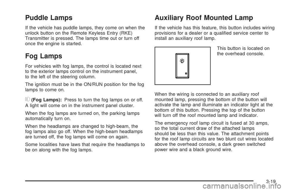
If the vehicle has this feature, this button includes wiring
provisions for a dealer or a quali�ed service center to
install an auxiliary roof lamp.
This button is located on
the overhead console.
When the wiring is connected to an auxiliary roof
mounted lamp, pressing the bottom of the button will
activate the lamp and illuminate an indicator light at the
bottom of this button. Pressing the top of the button
will turn off the roof mounted lamp and indicator.
The emergency roof lamp circuit is fused at 30 amps,
so the total current draw of the attached lamps
should be less than this value. The attachment points
for the roof lamp circuits are two blunt cut wires located
above the overhead console, a dark green switched
power wire and a black ground wire.
3-19
Page 223 of 600
Airbag Readiness Light
The system checks the airbag’s electrical system for
possible malfunctions. If the light stays on it indicates
there is an electrical problem. The system check
includes the airbag sensor, the pretensioners, the airbag
modules, the wiring and the crash sensing and
diagnostic module. For more information on the airbag
system, seeAirbag System on page 1-74.
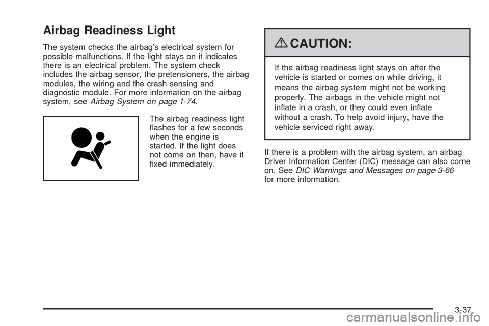
The airbag readiness light
�ashes for a few seconds
when the engine is
started. If the light does
not come on then, have it
�xed immediately.{CAUTION:
If the airbag readiness light stays on after the
vehicle is started or comes on while driving, it
means the airbag system might not be working
properly. The airbags in the vehicle might not
in�ate in a crash, or they could even in�ate
without a crash. To help avoid injury, have the
vehicle serviced right away.
If there is a problem with the airbag system, an airbag
Driver Information Center (DIC) message can also come
on. SeeDIC Warnings and Messages on page 3-66
for more information.
3-37
Page 253 of 600
Loading the Vehicle on page 4-32, andInflation - Tire
Pressure on page 5-73. The DIC also shows the tire
pressure values. See “DIC Operation and Displays
(With DIC Buttons)” earlier in this section. If the
tire pressure is low, the low tire pressure warning light
comes on. SeeTire Pressure Light on page 3-45.
CHECK TRAILER WIRING
On vehicles with the Integrated Trailer Brake Control
(ITBC) system, this message may display and a
chime may sound when one of the following conditions
exists:
A trailer with electric brakes becomes disconnected
from the vehicle.
� If the disconnect occurs while the vehicle is
stopped, this message clears itself after a
short time.
� If the disconnect occurs while the vehicle is
moving, this message stays on until the
ignition is turned off.
There is a short in the wiring to the electric trailer
brakes.When this message displays, power is no longer
available to the trailer brakes.
As soon as it is safe to do so, carefully pull your vehicle
over to the side of the road and turn the ignition off.
Check the wiring connection to the trailer and turn the
ignition back on. This message clears if the trailer
is reconnected. This message also clears if you
acknowledge it. If this message still displays, either
your vehicle or the trailer needs service. See your
dealer/retailer.
See “Integrated Trailer Brake Control System” under
Towing a Trailer on page 4-51for more information.
DRIVER DOOR OPEN
This message displays and a chime sounds if the driver
door is not fully closed and the vehicle is shifted out
of P (Park). Stop and turn off the vehicle, check the door
for obstructions, and close the door again. Check to
see if the message still appears on the DIC.
3-67
Page 259 of 600
SERVICE TRAILER BRAKE SYSTEM
On vehicles with the Integrated Trailer Brake Control
(ITBC) system, this message displays and a chime
sounds when there is a problem with the ITBC system.
When this message displays, power is no longer
available to the trailer brakes.
As soon as it is safe to do so, carefully pull your vehicle
over to the side of the road and turn the ignition off.
Check the wiring connection to the trailer and turn
the ignition back on. If this message still displays,
either your vehicle or the trailer needs service.
See your dealer/retailer.
See “Integrated Trailer Brake Control System” under
Towing a Trailer on page 4-51for more information.
STABILITRAK OFF
If your vehicle has StabiliTrak, this message displays
when you turn off StabiliTrak, or when the stability
control has been automatically disabled. To limit wheel
spin and realize the full bene�ts of the stability
enhancement system, you should normally leave
StabiliTrak on. However, you should turn StabiliTrak off
if your vehicle gets stuck in sand, mud, ice, or snow
and you want to rock your vehicle to attempt to free it,
or if you are driving in extreme off-road conditionsand require more wheel spin. SeeIf Your Vehicle is
Stuck in Sand, Mud, Ice, or Snow on page 4-30.
To turn the StabiliTrak system on or off, seeStabiliTrak
®
System on page 4-6.
There are several conditions that can cause this
message to appear.
One condition is overheating, which could occur if
StabiliTrak®activates continuously for an extended
period of time.
The message also displays if the brake system
warning light is on. SeeBrake System Warning
Light on page 3-42.
The message could display if the stability system
takes longer than usual to complete its diagnostic
checks due to driving conditions.
The message displays if an engine or vehicle
related problem has been detected and the vehicle
needs service. See your dealer/retailer.
The message also displays if the vehicle is shifted
into 4LO.
The message turns off as soon as the conditions that
caused the message to be displayed are no longer
present.
3-73
Page 371 of 600
See your dealer/retailer for additional advice and
information about using a snow plow on your vehicle.
Also, seeLoading the Vehicle on page 4-32.
Emergency Roof Lamp Provisions
Vehicles with the RPO VYU snow plow prep package
also have an emergency roof lamp provision package,
RPO TRW. Wiring for the emergency roof lamp is
provided above the overhead console. SeeAuxiliary
Roof Mounted Lamp on page 3-19for switch location.
Truck-Camper Loading Information
A vehicle speci�c Truck-Camper Loading
information label is attached to the inside of your
vehicle’s glove box. This label will tell you if
your vehicle can carry a slide-in camper, how
much of a load your vehicle can carry, and how to
correctly spread out the load. Also, it will help
you match the right slide-in camper to your vehicle.
When you carry a slide-in camper, the total
cargo load of your vehicle is the weight of the
camper, plus the following:
Everything else added to the camper after it
left the factory
Everything in the camper
All the people insideThe Cargo Weight Rating (CWR) is the maximum
weight of the load your vehicle can carry. It
does not include the weight of the people inside.
But, you can �gure about 150 lbs (68 kg) for
each seat.
The total cargo load must not be more than your
vehicle’s CWR.
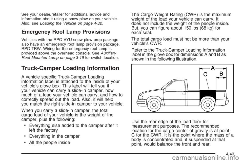
Refer to the Truck-Camper Loading Information
label in the glove box for dimensions A and B as
shown in the following illustration.
Use the rear edge of the load �oor for
measurement purposes. The recommended
location for the cargo center of gravity is at point
C for the CWR. It is the point where the mass of a
body is concentrated and, if suspended at that
point, would balance the front and rear.
4-43
Page 401 of 600
TRAILER GAIN – This setting is displayed anytime the
Trailer Brake Display Page is active. This setting
can be adjusted from 0.0 to 10.0 with either a trailer
connected or disconnected. To adjust the Trailer Gain,
press one of the Trailer Gain adjustment buttons
located on the Trailer Brake Control Panel. Press and
hold a gain button to cause the Trailer Gain to
continuously adjust. To turn the output to the trailer off,
adjust the Trailer Gain setting to 0.0 (zero).
0.0 (zero) gain is the factory default setting. To properly
adjust trailer gain, see the Trailer Gain Adjustment
Procedure later in this section.
TRAILER OUTPUT – This is displayed any time a trailer
with electric brakes is connected. Output to the electric
brakes is based on the amount of vehicle braking
present and relative to the Trailer Gain setting. Output is
displayed from 0 to 10 bars for each gain setting.
The Trailer Output will indicate “------“ontheTrailer
Brake Display Page whenever the following occur:
No trailer is connected.
A trailer without electric brakes is connected
(no DIC message is displayed).
A trailer with electric brakes has become
disconnected (a CHECK TRAILER WIRING
message will also be displayed on the DIC).
There is a fault present in the wiring to the electric
trailer brakes (a CHECK TRAILER WIRING
message will also be displayed on the DIC).
There is a fault in the ITBC system (a SERVICE
TRAILER BRAKE SYSTEM message will also
be displayed in the DIC).
Manual Trailer Brake Apply
The Manual Trailer Brake Apply Lever is located on the
Trailer Brake Control Panel and is used to apply the
trailer’s electric brakes independent of the vehicle’s
brakes. This lever is used in the Trailer Gain Adjustment
Procedure to properly adjust the power output to the
trailer brakes. Sliding the lever to the left will apply only
the trailer brakes. The power output to the trailer is
indicated in the Trailer Brake Display Page in the DIC. If
the vehicle’s service brakes are applied while using
the Manual Trailer Brake Apply Lever, the trailer output
power will be the greater of the two.
The trailer and the vehicle’s brake lamps will come on
when either vehicle braking or manual trailer brakes are
applied.
4-73
Page 403 of 600
Other ITBC Related DIC Messages
In addition to displaying TRAILER GAIN and TRAILER
OUTPUT through the DIC, trailer connection and
ITBC system status is displayed in the DIC.
TRAILER CONNECTED – This message will be brie�y
displayed when a trailer with electric brakes is �rst
connected to the vehicle. This message will
automatically turn off in about ten seconds. The driver
can also acknowledge this message before it
automatically turns off.
CHECK TRAILER WIRING – This message will be
displayed if:
1. The ITBC system �rst determines connection to a
trailer with electric brakes and then the trailer
harness becomes disconnected from the vehicle.
If the disconnect occurs while the vehicle is
stationary, this message will automatically turn off in
about thirty seconds. This message will also turn
off if the driver acknowledges this message off or if
the trailer harness is re-connected.
If the disconnect occurs while the vehicle is moving,
this message will continue until the ignition is
turned off. This message will also turn off if the
driver acknowledges this message off or if the trailer
harness is re-connected.2. There is an electrical fault in the wiring to the
electric trailer brakes. This message will continue as
long as there is an electrical fault in the trailer
wiring. This message will also turn off if the driver
acknowledges this message off.
To determine if the electrical fault is on the vehicle side
or trailer side of the trailer wiring harness connection,
do the following:
1. Disconnect the trailer wiring harness from the
vehicle.
2. Turn the ignition OFF.
3. Wait ten seconds, then turn the ignition back
to RUN.
4. If the CHECK TRAILER WIRING message
re-appears, the electrical fault is on the vehicle side.
If the CHECK TRAILER WIRING message only
re-appears when connecting the trailer wiring
harness to the vehicle, the electrical fault is on the
trailer side.
SERVICE TRAILER BRAKE SYSTEM – This message
will be displayed when there is a problem with the
ITBC system. If this message persists over multiple
ignition cycles there is a problem with the ITBC system.
Take the vehicle to an authorized GM dealer to have
the ITBC system diagnosed and repaired.
4-75
Page 404 of 600
If either the CHECK TRAILER WIRING or SERVICE
TRAILER BRAKE SYSTEM message is displayed while
driving the vehicle, power is no longer available to
the trailer brakes. When traffic conditions allow, carefully
pull the vehicle over to the side of the road and turn
the ignition off. Check the wiring connection to the trailer
and turn the ignition back on. If either of these
messages continues, either the vehicle or trailer needs
service.
An authorized GM dealer may be able to diagnose and
repair problems with the trailer. However, any
diagnosis and repair of the trailer is not covered under
the vehicle warranty. Please contact your trailer
dealer for assistance with trailer repairs and trailer
warranty information.Driving with a Trailer
{CAUTION:
When towing a trailer, exhaust gases may collect
at the rear of the vehicle and enter if the liftgate,
trunk/hatch, or rear-most window is open.
Engine exhaust contains carbon monoxide (CO)
which cannot be seen or smelled. It can cause
unconsciousness and even death.
To maximize safety when towing a trailer:
Have the exhaust system inspected for
leaks and make necessary repairs before
starting a trip.
Never drive with the liftgate, trunk/hatch, or
rear-most window open.
Fully open the air outlets on or under the
instrument panel.
Adjust the Climate Control system to a setting
that brings in only outside air and set the fan
speed to the highest setting. See Climate
Control System in the Index.
For more information about carbon monoxide, see
Engine Exhaust on page 2-55.
4-76