wiring CHEVROLET SILVERADO 2010 2.G Owners Manual
[x] Cancel search | Manufacturer: CHEVROLET, Model Year: 2010, Model line: SILVERADO, Model: CHEVROLET SILVERADO 2010 2.GPages: 626, PDF Size: 4.8 MB
Page 134 of 626
Servicing Your Airbag-Equipped
Vehicle
Airbags affect how the vehicle should be serviced.
There are parts of the airbag system in several places
around the vehicle. Your dealer and the service manual
have information about servicing the vehicle and the
airbag system. To purchase a service manual, see
Service Publications Ordering Information
on
page 8‑16.
{WARNING:
For up to 10 seconds after the ignition is turned off
and the battery is disconnected, an airbag can still
inflate during improper service. You can be injured
if you are close to an airbag when it inflates. Avoid
yellow connectors. They are probably part of the
airbag system. Be sure to follow proper service
procedures, and make sure the person performing
work for you is qualified to do so.
Adding Equipment to Your
Airbag-Equipped Vehicle
Q: Is there anything I might add to or change about the vehicle that could keep the airbags from
working properly?
A: Yes. If you add things that change your vehicle's
frame, bumper system, height, front end or side
sheet metal, they may keep the airbag system from
working properly. Changing or moving any parts of
the front seats, safety belts, the airbag sensing and
diagnostic module, steering wheel, instrument panel,
roof-rail airbag modules, ceiling headliner or pillar
garnish trim, overhead console, front sensors, side
impact sensors, rollover sensor module, or airbag
wiring can affect the operation of the airbag system.
In addition, the vehicle may have a passenger
sensing system for the right front passenger's
position, which includes sensors that are part of the
passenger's seat. The passenger sensing system
may not operate properly if the original seat trim is
replaced with non-GM covers, upholstery or trim,
or with GM covers, upholstery or trim designed for a
different vehicle. Any object, such as an aftermarket
seat heater or a comfort enhancing pad or device,
installed under or on top of the seat fabric, could
also interfere with the operation of the passenger
sensing system. This could either prevent proper
2-92
Page 135 of 626
deployment of the passenger airbag(s) or prevent
the passenger sensing system from properly turning
off the passenger airbag(s). SeePassenger Sensing
System on page 2‑86.
If you have any questions about this, you should
contact Customer Assistance before you modify
your vehicle. The phone numbers and addresses for
Customer Assistance are in Step Two of the
Customer Satisfaction Procedure in this manual.
See Customer Satisfaction Procedure on page 8‑2.
If the vehicle has rollover roof-rail airbags, see
Different Size Tires and Wheels
on page 6‑85for
additional important information.
Q: What if I added a snow plow? Will it keep the airbags from working properly?
A: We have designed our airbag systems to work
properly under a wide range of conditions, including
snow plowing with vehicles that have the optional
Snow Plow Prep Package (RPO VYU). But do not
change or defeat the snow plow's “tripping
mechanism.” If you do, it can damage your snow
plow and your vehicle, and it may cause an airbag
inflation. Q: Because I have a disability, I have to get my
vehicle modified. How can I find out whether this
will affect my airbag system?
A: If you have questions, call Customer Assistance.
The phone numbers and addresses for Customer
Assistance are in Step Two of the Customer
Satisfaction Procedure in this manual. See
Customer Satisfaction Procedure on page 8‑2.
In addition, your dealer and the service manual have
information about the location of the airbag sensors,
sensing and diagnostic module and airbag wiring.
2-93
Page 205 of 626
Disconnecting the Rear Vision Camera
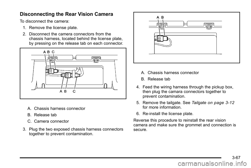
To disconnect the camera:1. Remove the license plate.
2. Disconnect the camera connectors from the chassis harness, located behind the license plate,
by pressing on the release tab on each connector.
A. Chassis harness connector
B. Release tab
C. Camera connector
3. Plug the two exposed chassis harness connectors together to prevent contamination.
A. Chassis harness connector
B. Release tab
4. Feed the wiring harness through the pickup box, then plug the camara connectors together to
prevent contamination.
5. Remove the tailgate. See Tailgate
on page 3‑12for more information.
6. Re‐install the license plate.
Reverse this procedure to reinstall the rear vision
camera and make sure the grommet and connection is
secure.
3-67
Page 232 of 626
Auxiliary Roof-Mounted Lamp
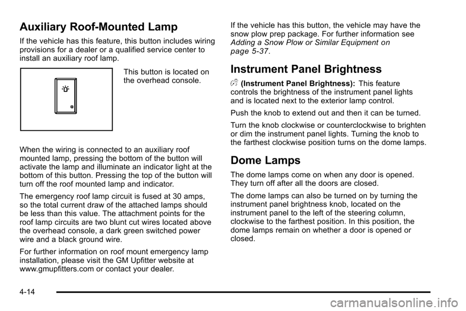
If the vehicle has this feature, this button includes wiring
provisions for a dealer or a qualified service center to
install an auxiliary roof lamp.
This button is located on
the overhead console.
When the wiring is connected to an auxiliary roof
mounted lamp, pressing the bottom of the button will
activate the lamp and illuminate an indicator light at the
bottom of this button. Pressing the top of the button will
turn off the roof mounted lamp and indicator.
The emergency roof lamp circuit is fused at 30 amps,
so the total current draw of the attached lamps should
be less than this value. The attachment points for the
roof lamp circuits are two blunt cut wires located above
the overhead console, a dark green switched power
wire and a black ground wire.
For further information on roof mount emergency lamp
installation, please visit the GM Upfitter website at
www.gmupfitters.com or contact your dealer. If the vehicle has this button, the vehicle may have the
snow plow prep package. For further information see
Adding a Snow Plow or Similar Equipment
on
page 5‑37.
Instrument Panel Brightness
D (Instrument Panel Brightness): This feature
controls the brightness of the instrument panel lights
and is located next to the exterior lamp control.
Push the knob to extend out and then it can be turned.
Turn the knob clockwise or counterclockwise to brighten
or dim the instrument panel lights. Turning the knob to
the farthest clockwise position turns on the dome lamps.
Dome Lamps
The dome lamps come on when any door is opened.
They turn off after all the doors are closed.
The dome lamps can also be turned on by turning the
instrument panel brightness knob, located on the
instrument panel to the left of the steering column,
clockwise to the farthest position. In this position, the
dome lamps remain on whether a door is opened or
closed.
4-14
Page 250 of 626
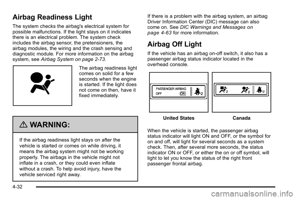
Airbag Readiness Light
The system checks the airbag's electrical system for
possible malfunctions. If the light stays on it indicates
there is an electrical problem. The system check
includes the airbag sensor, the pretensioners, the
airbag modules, the wiring and the crash sensing and
diagnostic module. For more information on the airbag
system, seeAirbag System on page 2‑73.
The airbag readiness light
comes on solid for a few
seconds when the engine
is started. If the light does
not come on then, have it
fixed immediately.
{WARNING:
If the airbag readiness light stays on after the
vehicle is started or comes on while driving, it
means the airbag system might not be working
properly. The airbags in the vehicle might not
inflate in a crash, or they could even inflate
without a crash. To help avoid injury, have the
vehicle serviced right away. If there is a problem with the airbag system, an airbag
Driver Information Center (DIC) message can also
come on. See
DIC Warnings and Messages
on
page 4‑63for more information.
Airbag Off Light
If the vehicle has an airbag on-off switch, it also has a
passenger airbag status indicator located in the
overhead console.
United StatesCanada
When the vehicle is started, the passenger airbag
status indicator will light ON and OFF, or the symbol for
on and off, will light for several seconds as a system
check. Then, after several more seconds, the status
indicator ON or OFF, or either the on or off symbol, will
light to let you know the status of the right front
passenger frontal airbag.
4-32
Page 282 of 626
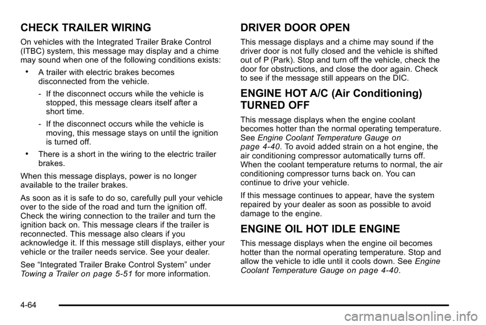
CHECK TRAILER WIRING
On vehicles with the Integrated Trailer Brake Control
(ITBC) system, this message may display and a chime
may sound when one of the following conditions exists:
.A trailer with electric brakes becomes
disconnected from the vehicle.
‐If the disconnect occurs while the vehicle is
stopped, this message clears itself after a
short time.
‐ If the disconnect occurs while the vehicle is
moving, this message stays on until the ignition
is turned off.
.There is a short in the wiring to the electric trailer
brakes.
When this message displays, power is no longer
available to the trailer brakes.
As soon as it is safe to do so, carefully pull your vehicle
over to the side of the road and turn the ignition off.
Check the wiring connection to the trailer and turn the
ignition back on. This message clears if the trailer is
reconnected. This message also clears if you
acknowledge it. If this message still displays, either your
vehicle or the trailer needs service. See your dealer.
See “Integrated Trailer Brake Control System” under
Towing a Trailer
on page 5‑51for more information.
DRIVER DOOR OPEN
This message displays and a chime may sound if the
driver door is not fully closed and the vehicle is shifted
out of P (Park). Stop and turn off the vehicle, check the
door for obstructions, and close the door again. Check
to see if the message still appears on the DIC.
ENGINE HOT A/C (Air Conditioning)
TURNED OFF
This message displays when the engine coolant
becomes hotter than the normal operating temperature.
See Engine Coolant Temperature Gauge
on
page 4‑40. To avoid added strain on a hot engine, the
air conditioning compressor automatically turns off.
When the coolant temperature returns to normal, the air
conditioning compressor turns back on. You can
continue to drive your vehicle.
If this message continues to appear, have the system
repaired by your dealer as soon as possible to avoid
damage to the engine.
ENGINE OIL HOT IDLE ENGINE
This message displays when the engine oil becomes
hotter than the normal operating temperature. Stop and
allow the vehicle to idle until it cools down. See Engine
Coolant Temperature Gauge
on page 4‑40.
4-64
Page 287 of 626
SERVICE THEFT DETERRENT SYSTEM
This message displays when there is a problem
with the theft-deterrent system. The vehicle may
or may not restart so you may want to take the vehicle
to your dealer before turning off the engine. See
PASS-Key
®III+ Electronic Immobilizer Operationon
page 3‑19for more information.
SERVICE TIRE MONITOR SYSTEM
If your vehicle has the Tire Pressure Monitor System
(TPMS), this message displays if a part on the system
is not working properly. The tire pressure light also
flashes and then remains on during the same ignition
cycle. See Tire Pressure Light
on page 4‑40. Several
conditions may cause this message to appear. See Tire
Pressure Monitor Operation
on page 6‑76for more
information. If the warning comes on and stays on,
there may be a problem with the TPMS. See your
dealer.
SERVICE TRACTION CONTROL
If your vehicle has StabiliTrak, this message displays
when there is a problem with the Traction Control
System (TCS). When this message displays, the
system will not limit wheel spin. Adjust your driving
accordingly. See your dealer for service. See
StabiliTrak
®Systemon page 5‑6for more
information.
SERVICE TRAILER BRAKE SYSTEM
On vehicles with the Integrated Trailer Brake Control
(ITBC) system, this message displays and a chime may
sound when there is a problem with the ITBC system.
When this message displays, power is no longer
available to the trailer brakes.
As soon as it is safe to do so, carefully pull your vehicle
over to the side of the road and turn the ignition off.
Check the wiring connection to the trailer and turn the
ignition back on. If this message still displays, either
your vehicle or the trailer needs service. See your
dealer.
See “Integrated Trailer Brake Control System” under
Towing a Trailer
on page 5‑51for more information.
4-69
Page 406 of 626
You can add heavier equipment on the front of the
vehicle if you compensate for it by carrying fewer
passengers, less cargo, or by positioning cargo toward
the rear. This has the effect of reducing the load on the
front. However, the front GAWR, rear GAWR, and the
Gross Vehicle Weight Rating (GVWR) must never be
exceeded.
{WARNING:
On some vehicles that have certain front mounted
equipment, such as a snow plow, it may be
possible to load the front axle to the front gross
axle weight rating (GAWR) but not have enough
weight on the rear axle to have proper braking
performance. If your brakes can not work properly,
you could have a crash. To help your brakes work
properly when a snow plow is installed, always
follow the snow plow manufacturer or installer's
recommendation for rear ballast to ensure a
proper front and rear weight distribution ratio,
even though the actual front weight may be less
than the front GAWR, and the total vehicle weight
is less than the gross vehicle weight rating
(GVWR). Maintaining a proper front and rear
weight distribution ratio is necessary to provide
proper braking performance.Total vehicle reserve capacity is the difference between
the GVWR and the weight of the truck with full fuel and
passengers. It is the amount of weight that can be
added to the vehicle before reaching the GVWR. Keep
in mind that reserve capacity numbers are intended as
a guide when selecting the amount of equipment or
cargo the truck can carry. If unsure of the vehicle's front,
rear, or total weight, go to a weigh station and weigh the
vehicle. Your dealer can also help with this.
The total vehicle reserve capacity for the vehicle can be
found in the lower right corner of the Certification/Tire
label as shown previously.
See your dealer for additional advice and information
about using a snow plow on the vehicle. Also, see
Loading the Vehicle on page 5‑29.
Emergency Roof Lamp Provisions
Vehicles with the RPO VYU snow plow prep package
also have an emergency roof lamp provision package,
RPO TRW. Wiring for the emergency roof lamp is
provided above the overhead console. See
Auxiliary
Roof-Mounted Lamp
on page 4‑14for switch location.
5-40
Page 435 of 626
The Trailer Output will indicate“- - - - - -“on the Trailer
Brake Display Page whenever the following occur:
.No trailer is connected.
.A trailer without electric brakes is connected (no
DIC message is displayed).
.A trailer with electric brakes has become
disconnected (a CHECK TRAILER WIRING
message will also be displayed on the DIC).
.There is a fault present in the wiring to the electric
trailer brakes (a CHECK TRAILER WIRING
message will also be displayed on the DIC).
.There is a fault in the ITBC system (a SERVICE
TRAILER BRAKE SYSTEM message will also be
displayed in the DIC).
Manual Trailer Brake Apply
The Manual Trailer Brake Apply Lever is located on the
Trailer Brake Control Panel and is used to apply the
trailer ’s electric brakes independent of the vehicle’ s
brakes. This lever is used in the Trailer Gain Adjustment
Procedure to properly adjust the power output to the
trailer brakes. Sliding the lever to the left will apply only
the trailer brakes. The power output to the trailer is
indicated in the Trailer Brake Display Page in the DIC.
If the vehicle’s service brakes are applied while using
the Manual Trailer Brake Apply Lever, the trailer output
power will be the greater of the two. The trailer and the vehicle's brake lamps will come on
when either vehicle braking or manual trailer brakes are
applied.
Trailer Gain Adjustment Procedure
Trailer Gain should be set for a specific trailering
condition and must be adjusted any time vehicle
loading, trailer loading or road surface conditions
change.
Setting the Trailer Gain properly is needed for the best
trailer stopping performance. A trailer that is
over-gained may result in locked trailer brakes. A trailer
that is under-gained may result in not enough trailer
braking. Both of these conditions may result in poorer
stopping and stability of the vehicle and trailer.
Use the following procedure to correctly adjust Trailer
Gain for each towing condition:
1. Make sure the trailer brakes are in proper working condition.
2. Connect a properly loaded trailer to the vehicle and make all necessary mechanical and electrical
connections. See Loading the Vehicle
on
page 5‑29for more information.
5-69
Page 437 of 626
CHECK TRAILER WIRING–This message will be
displayed if:
1. The ITBC system first determines connection to a trailer with electric brakes and then the trailer
harness becomes disconnected from the vehicle.
If the disconnect occurs while the vehicle is
stationary, this message will automatically turn off
in about thirty seconds. This message will also turn
off if the driver acknowledges this message off or if
the trailer harness is re-connected.
If the disconnect occurs while the vehicle is
moving, this message will continue until the ignition
is turned off. This message will also turn off if the
driver acknowledges this message off or if the
trailer harness is re-connected.
2. There is an electrical fault in the wiring to the electric trailer brakes. This message will continue
as long as there is an electrical fault in the trailer
wiring. This message will also turn off if the driver
acknowledges this message off.
To determine if the electrical fault is on the vehicle side
or trailer side of the trailer wiring harness connection,
do the following: 1. Disconnect the trailer wiring harness from the vehicle.
2. Turn the ignition OFF. 3. Wait ten seconds, then turn the ignition back
to RUN.
4. If the CHECK TRAILER WIRING message re-appears, the electrical fault is on the
vehicle side.
If the CHECK TRAILER WIRING message only
re-appears when connecting the trailer wiring
harness to the vehicle, the electrical fault is on the
trailer side.
SERVICE TRAILER BRAKE SYSTEM –This message
will be displayed when there is a problem with the ITBC
system. If this message persists over multiple ignition
cycles there is a problem with the ITBC system. Take
the vehicle to an authorized GM dealer to have the
ITBC system diagnosed and repaired.
If either the CHECK TRAILER WIRING or SERVICE
TRAILER BRAKE SYSTEM message is displayed while
driving the vehicle, power is no longer available to the
trailer brakes. When traffic conditions allow, carefully
pull the vehicle over to the side of the road and turn the
ignition off. Check the wiring connection to the trailer
and turn the ignition back on. If either of these
messages continues, either the vehicle or trailer needs
service.
5-71