width CHEVROLET SILVERADO 2024 Owners Manual
[x] Cancel search | Manufacturer: CHEVROLET, Model Year: 2024, Model line: SILVERADO, Model: CHEVROLET SILVERADO 2024Pages: 433, PDF Size: 14.15 MB
Page 30 of 433
Chevrolet Silverado 2500 HD/3500 HD Owner Manual (GMNA-Localizing-U.
S./Canada/Mexico-16908339) - 2024 - CRC - 12/5/22
28 Keys, Doors, and Windows
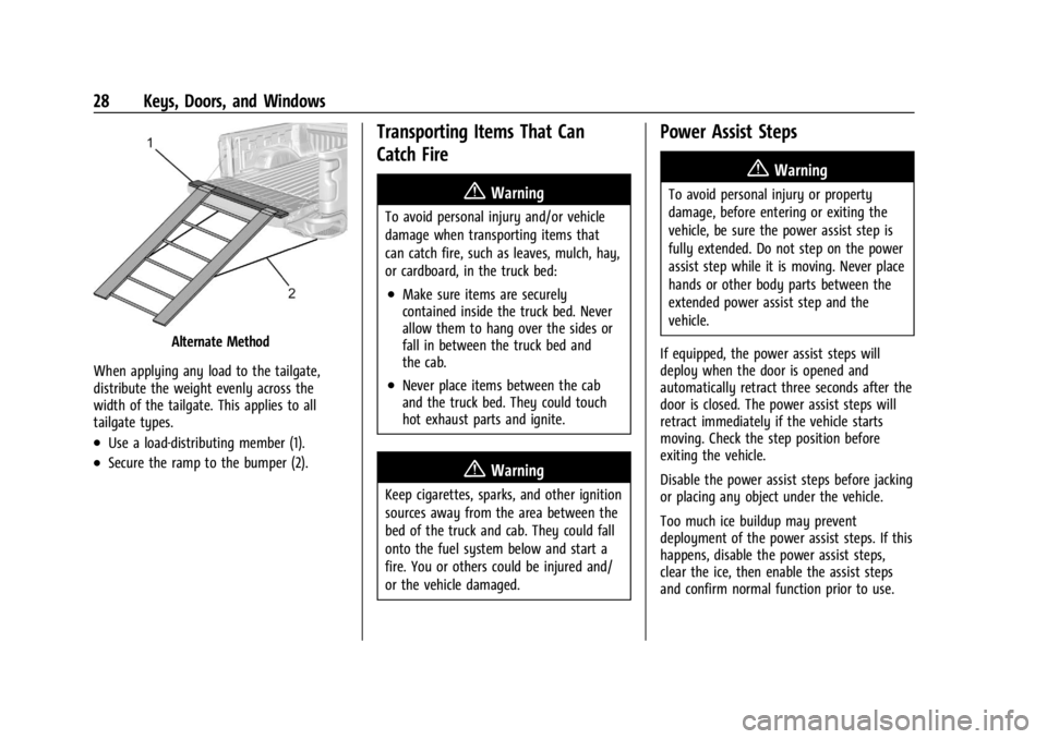
Alternate Method
When applying any load to the tailgate,
distribute the weight evenly across the
width of the tailgate. This applies to all
tailgate types.
.Use a load-distributing member (1).
.Secure the ramp to the bumper (2).
Transporting Items That Can
Catch Fire
{Warning
To avoid personal injury and/or vehicle
damage when transporting items that
can catch fire, such as leaves, mulch, hay,
or cardboard, in the truck bed:
.Make sure items are securely
contained inside the truck bed. Never
allow them to hang over the sides or
fall in between the truck bed and
the cab.
.Never place items between the cab
and the truck bed. They could touch
hot exhaust parts and ignite.
{Warning
Keep cigarettes, sparks, and other ignition
sources away from the area between the
bed of the truck and cab. They could fall
onto the fuel system below and start a
fire. You or others could be injured and/
or the vehicle damaged.
Power Assist Steps
{Warning
To avoid personal injury or property
damage, before entering or exiting the
vehicle, be sure the power assist step is
fully extended. Do not step on the power
assist step while it is moving. Never place
hands or other body parts between the
extended power assist step and the
vehicle.
If equipped, the power assist steps will
deploy when the door is opened and
automatically retract three seconds after the
door is closed. The power assist steps will
retract immediately if the vehicle starts
moving. Check the step position before
exiting the vehicle.
Disable the power assist steps before jacking
or placing any object under the vehicle.
Too much ice buildup may prevent
deployment of the power assist steps. If this
happens, disable the power assist steps,
clear the ice, then enable the assist steps
and confirm normal function prior to use.
Page 210 of 433
Chevrolet Silverado 2500 HD/3500 HD Owner Manual (GMNA-Localizing-U.
S./Canada/Mexico-16908339) - 2024 - CRC - 12/12/22
208 Driving and Operating
Warning (Continued)
.Do not leave an unsecured child
restraint in the vehicle.
.When you carry something inside
the vehicle, secure it whenever
you can.
.Do not leave a seat folded down
unless you need to.
There is also important loading
information for off-road driving in this
manual. See “Loading the Vehicle for
Off-Road Driving“ underOff-Road
Driving 0197.
Two-Tiered Loading
Depending on the model of the pickup,
an upper load platform can be created
by positioning three or four 5 cm (2 in)
by 15 cm (6 in) wooden planks across
the width of the pickup box. The planks
must be inserted in the pickup box
depressions. When using this upper load platform,
be sure the load is securely tied down
to prevent it from shifting. The load's
center of gravity should be positioned
in a zone over the rear axle. The zone is
located in the area between the front
of each wheel well and the rear of each
wheel well. The center of gravity height
must not extend above the top of the
pickup box flareboard.
Any load that extends beyond the
vehicle's taillamp area must be properly
marked according to local laws and
regulations.
Remember not to exceed the Gross Axle
Weight Rating (GAWR) of the front or
rear axle.
Add-On Equipment
When carrying removable items, a limit
on how many people carried inside the
vehicle may be necessary. Be sure to
weigh the vehicle before buying and
installing the new equipment.
Caution
Overloading the vehicle may cause
damage. Repairs would not be covered by
the vehicle warranty. Do not overload the
vehicle.
Remember not to exceed the Gross Axle
Weight Rating (GAWR) of the front or
rear axle.
* Equipment Maximum Weight
Ladder Rack and
Cargo 340 kg (750 lb)
Cross Toolbox and
Cargo 181 kg (400 lb)
Side Boxes and
Cargo 113 kg per side
(250 lb per side)
* The combined weight for all
rail-mounted equipment should not
exceed 454 kg (1,000 lb).
Page 295 of 433
Chevrolet Silverado 2500 HD/3500 HD Owner Manual (GMNA-Localizing-U.
S./Canada/Mexico-16908339) - 2024 - CRC - 12/12/22
Driving and Operating 293
.Trailer Width: 120 cm (47.2 in)–260 cm
(102.3 in). Measure from the left edge of
the trailer to the right edge.
.Trailer Height: 1 cm (0.39 in) –450 cm
(177.1 in). Measure from the ground to
tallest point of the trailer.
.Hitching Point Length: 180 cm (70.8 in) –
970 cm (381.8 in). Measure from the
center of the coupler to the middle of
tires.
.Trailer Tongue Length: 50 cm (19.6 in) –
220 cm (86.6 in). Measure from the center
of the coupler to the trailer front wall if
trailer has a flat front. If it does not have
a flat front, measure from the center of
the coupler to the point where the taper
meets the full width of the trailer.
.Vehicle Hitch Height: 10 cm (3.9 in) –
100 cm (39.3 in). Measure from the
ground to the top of coupler.
.Vehicle Hitch Length: 10 cm (3.9 in) –
100 cm (39.3 in). Measure from the hitch
receiver to the center of ball.
Dimensions for a bed hitch (gooseneck or
fifth wheel) trailer:
.Trailer Length: 300 cm (118.1 in) –2500 cm
(984.2 in). Measure from the front bottom
corner of the trailer to the furthest rear
point of the trailer.
.Trailer Box Width: 3 cm (1 in) –300 cm
(118.1 in). Measure the flat width at the
front bottom corners of the trailer.
.Hitching Point Length: 3 cm (1 in) –
1524 cm (600 in). Measure from the center
of the king pin (for fifth wheel) or coupler
(for gooseneck) to the middle of tires.
.Vehicle Cab to Trailer Length: 3 cm (1 in) –
610 cm (240.2 in). Measure from the back
of the vehicle cab to the front bottom
corner of the trailer.
.Vehicle Cab to Hitch Length: 3 cm (1 in) –
305 cm (120.1 in). Measure from the back
of vehicle cab to the center of the king
pin (for fifth wheel) or coupler (for
gooseneck).
Rear Trailer Guidance Setup
If equipped, a rear trailer camera must be
mounted on the trailer and electrically
connected to the vehicle before rear trailer
guidance feature can be used. See Assistance
Systems for Parking or Backing 0247.
Follow the on-screen instructions to enter
trailer dimensions.
Trailer dimensions must be in range to
enable this feature.
.Trailer Length: 300 cm (118.1 in) –1300 cm
(511.8 in). Measure from center of coupler
to furthest rear point on the trailer.
1. If trailer dimensions are out of range, this feature will be unavailable.
2. Ensure rear trailer camera is connected.
3. Follow the on-screen instructions to drive forward to complete calibration.
Jack-Knife Alert Setup
If equipped, follow the on-screen instructions
to drive forward to complete calibration.
Trailer Length Indicator Setup
If equipped, follow the on-screen instructions
to drive forward to complete calibration.
Trailer Side Blind Zone Alert Setup
If equipped, trailer dimensions must be in
range to enable this feature.
Follow the on-screen instructions to enter
trailer dimensions.
.Trailer Length: 300 cm (118.1 in) –1200 cm
(472.4 in). Measure from center of coupler
to furthest rear point on the trailer.
.Vehicle Hitch Length: 10 cm (3.9 in) –
100 cm (839.3 in). Measure from the hitch
receiver to the center of ball.
Page 343 of 433
Chevrolet Silverado 2500 HD/3500 HD Owner Manual (GMNA-Localizing-U.
S./Canada/Mexico-16908339) - 2024 - CRC - 12/5/22
Vehicle Care 341
Winter tires with the same speed rating as
the original equipment tires may not be
available for H, V, W, Y, and ZR speed rated
tires. If winter tires with a lower speed
rating are chosen, never exceed the tire's
maximum speed capability.
All-Terrain Tires
This vehicle may have all-terrain or
mud-terrain tires. These tires provide good
performance on most road surfaces, weather
conditions, and for off-road driving. See
Off-Road Driving0197.
The tread pattern on these tires may wear
more unevenly than other tires. Consider
rotating the tires more frequently than at
12 000 km (7,500 mi) intervals if irregular
wear is noted when the tires are inspected.
See Tire Inspection 0351.
Tire Sidewall Labeling
Useful information about a tire is
molded into its sidewall. The example
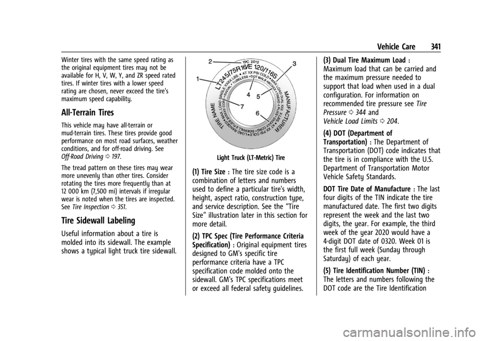
shows a typical light truck tire sidewall.
Light Truck (LT-Metric) Tire
(1) Tire Size:The tire size code is a
combination of letters and numbers
used to define a particular tire's width,
height, aspect ratio, construction type,
and service description. See the “Tire
Size” illustration later in this section for
more detail.
(2) TPC Spec (Tire Performance Criteria
Specification)
:Original equipment tires
designed to GM's specific tire
performance criteria have a TPC
specification code molded onto the
sidewall. GM's TPC specifications meet
or exceed all federal safety guidelines. (3) Dual Tire Maximum Load
:
Maximum load that can be carried and
the maximum pressure needed to
support that load when used in a dual
configuration. For information on
recommended tire pressure see
Tire
Pressure 0344 and
Vehicle Load Limits 0204.
(4) DOT (Department of
Transportation)
:The Department of
Transportation (DOT) code indicates that
the tire is in compliance with the U.S.
Department of Transportation Motor
Vehicle Safety Standards.
DOT Tire Date of Manufacture
:The last
four digits of the TIN indicate the tire
manufactured date. The first two digits
represent the week and the last two
digits, the year. For example, the third
week of the year 2020 would have a
4-digit DOT date of 0320. Week 01 is
the first full week (Sunday through
Saturday) of each year.
(5) Tire Identification Number (TIN)
:
The letters and numbers following the
DOT code are the Tire Identification
Page 344 of 433
Chevrolet Silverado 2500 HD/3500 HD Owner Manual (GMNA-Localizing-U.
S./Canada/Mexico-16908339) - 2024 - CRC - 12/5/22
342 Vehicle Care
Number (TIN). The TIN shows the
manufacturer and plant code, tire size,
and date the tire was manufactured.
The TIN is molded onto both sides of
the tire, although only one side may
have the date of manufacture.
(6) Tire Ply Material
:The type of cord
and number of plies in the sidewall and
under the tread.
(7) Single Tire Maximum Load
:
Maximum load that can be carried and
the maximum pressure needed to
support that load when used as a
single. For information on
recommended tire pressure see Tire
Pressure 0344 and
Vehicle Load Limits 0204.
Tire Designations
Tire Size
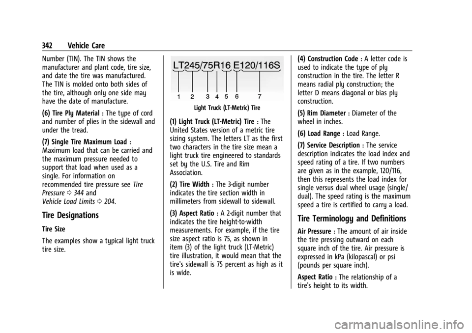
The examples show a typical light truck
tire size.
Light Truck (LT-Metric) Tire
(1) Light Truck (LT-Metric) Tire:The
United States version of a metric tire
sizing system. The letters LT as the first
two characters in the tire size mean a
light truck tire engineered to standards
set by the U.S. Tire and Rim
Association.
(2) Tire Width
:The 3-digit number
indicates the tire section width in
millimeters from sidewall to sidewall.
(3) Aspect Ratio
:A 2-digit number that
indicates the tire height-to-width
measurements. For example, if the tire
size aspect ratio is 75, as shown in
item (3) of the light truck (LT-Metric)
tire illustration, it would mean that the
tire's sidewall is 75 percent as high as it
is wide. (4) Construction Code
:A letter code is
used to indicate the type of ply
construction in the tire. The letter R
means radial ply construction; the
letter D means diagonal or bias ply
construction.
(5) Rim Diameter
:Diameter of the
wheel in inches.
(6) Load Range
:Load Range.
(7) Service Description
:The service
description indicates the load index and
speed rating of a tire. If two numbers
are given as in the example, 120/116,
then this represents the load index for
single versus dual wheel usage (single/
dual). The speed rating is the maximum
speed a tire is certified to carry a load.
Tire Terminology and Definitions
Air Pressure:The amount of air inside
the tire pressing outward on each
square inch of the tire. Air pressure is
expressed in kPa (kilopascal) or psi
(pounds per square inch).
Aspect Ratio
:The relationship of a
tire's height to its width.
Page 358 of 433
Chevrolet Silverado 2500 HD/3500 HD Owner Manual (GMNA-Localizing-U.
S./Canada/Mexico-16908339) - 2024 - CRC - 12/5/22
356 Vehicle Care
Warning (Continued)
crash and serious injury. Only use GM
specific wheel and tire systems developed
for the vehicle, and have them properly
installed by a GM certified technician.
See Buying New Tires 0354 and
Accessories and Modifications 0304.
Uniform Tire Quality Grading
The following information relates to the
system developed by the United States
National Highway Traffic Safety
Administration (NHTSA), which grades
tires by treadwear, traction, and
temperature performance. This applies
only to vehicles sold in the United
States. The grades are molded on the
sidewalls of most passenger car tires.
The Uniform Tire Quality Grading
(UTQG) system does not apply to deep
tread, winter tires, compact spare tires,
tires with nominal rim diameters of
10 to 12 inches (25 to 30 cm), or to some
limited-production tires. While the tires available on General
Motors passenger cars and light trucks
may vary with respect to these grades,
they must also conform to federal
safety requirements and additional
General Motors Tire Performance
Criteria (TPC) standards.
Quality grades can be found where
applicable on the tire sidewall between
tread shoulder and maximum section
width. For example:
Treadwear 200 Traction AA Temperature A
All Passenger Car Tires Must Conform to
Federal Safety Requirements In Addition
To These Grades.
Treadwear
The treadwear grade is a comparative
rating based on the wear rate of the
tire when tested under controlled
conditions on a specified government
test course. For example, a tire graded
150 would wear one and one-half (1½)
times as well on the government course
as a tire graded 100. The relative
performance of tires depends upon theactual conditions of their use, however,
and may depart significantly from the
norm due to variations in driving habits,
service practices and differences in road
characteristics and climate.
Traction
The traction grades, from highest to
lowest, are AA, A, B, and C. Those
grades represent the tire's ability to
stop on wet pavement as measured
under controlled conditions on specified
government test surfaces of asphalt and
concrete. A tire marked C may have
poor traction performance. Warning:
The traction grade assigned to this tire
is based on straight-ahead braking
traction tests, and does not include
acceleration, cornering, hydroplaning,
or peak traction characteristics.
Temperature
The temperature grades are A (the
highest), B, and C, representing the
tire's resistance to the generation of
heat and its ability to dissipate heat
when tested under controlled conditions
Page 359 of 433
Chevrolet Silverado 2500 HD/3500 HD Owner Manual (GMNA-Localizing-U.
S./Canada/Mexico-16908339) - 2024 - CRC - 12/5/22
Vehicle Care 357
on a specified indoor laboratory test
wheel. Sustained high temperature can
cause the material of the tire to
degenerate and reduce tire life, and
excessive temperature can lead to
sudden tire failure. The grade C
corresponds to a level of performance
which all passenger car tires must meet
under the Federal Motor Safety
Standard No. 109. Grades B and A
represent higher levels of performance
on the laboratory test wheel than the
minimum required by law. Warning:
The temperature grade for this tire is
established for a tire that is properly
inflated and not overloaded. Excessive
speed, underinflation, or excessive
loading, either separately or in
combination, can cause heat buildup
and possible tire failure.
Wheel Alignment and Tire
Balance
The tires and wheels were aligned and
balanced at the factory to provide the
longest tire life and best overall
performance. Adjustments to wheelalignment and tire balancing are not
necessary on a regular basis. Consider an
alignment check if there is unusual tire wear
or the vehicle is significantly pulling to one
side or the other. Some slight pull to the
left or right, depending on the crown of the
road and/or other road surface variations
such as troughs or ruts, is normal. If the
vehicle is vibrating when driving on a
smooth road, the tires and wheels may
need to be rebalanced. See your dealer for
proper diagnosis.
Wheel Replacement
Replace any wheel that is bent, cracked,
or badly rusted or corroded. If wheel nuts
keep coming loose, the wheel, wheel bolts,
and wheel nuts should be replaced. If the
wheel leaks air, replace it. Some aluminum
wheels can be repaired. See your dealer if
any of these conditions exist.
Your dealer will know the kind of wheel that
is needed.
Each new wheel should have the same
load-carrying capacity, diameter, width,
offset, and be mounted the same way as
the one it replaces.
Replace wheels, wheel bolts, wheel nuts,
or Tire Pressure Monitor System (TPMS)
sensors with new GM original equipment
parts.
{Warning
Using the wrong replacement wheels,
wheel bolts, or wheel nuts can be
dangerous. It could affect the braking and
handling of the vehicle. Tires can lose air
and cause loss of control, resulting in a
crash. Always use the correct wheel,
wheel bolts, and wheel nuts for
replacement.
{Warning
Replacing a wheel with a used one is
dangerous. How it has been used or how
far it has been driven may be unknown.
It could fail suddenly and cause a crash.
When replacing wheels, use a new GM
original equipment wheel.