CHEVROLET SILVERADO 2500 2019 Owners Manual
Manufacturer: CHEVROLET, Model Year: 2019, Model line: SILVERADO 2500, Model: CHEVROLET SILVERADO 2500 2019Pages: 489, PDF Size: 6.81 MB
Page 311 of 489
Chevrolet Silverado LD 1500 and Silverado 2500/3500 Owner Manual (GMNA-
Localizing-U.S./Canada-12162993) - 2019 - crc - 4/4/18
310 Driving and Operating
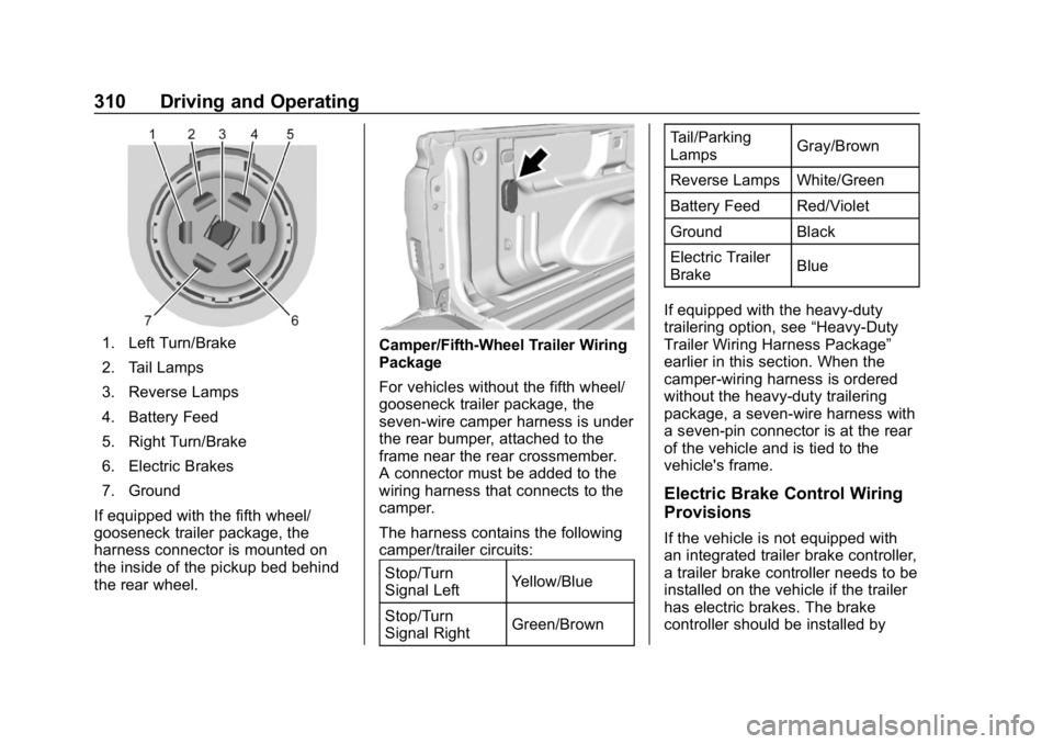
1. Left Turn/Brake
2. Tail Lamps
3. Reverse Lamps
4. Battery Feed
5. Right Turn/Brake
6. Electric Brakes
7. Ground
If equipped with the fifth wheel/
gooseneck trailer package, the
harness connector is mounted on
the inside of the pickup bed behind
the rear wheel.Camper/Fifth-Wheel Trailer Wiring
Package
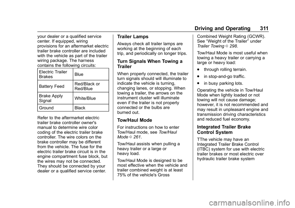
For vehicles without the fifth wheel/
gooseneck trailer package, the
seven-wire camper harness is under
the rear bumper, attached to the
frame near the rear crossmember.
A connector must be added to the
wiring harness that connects to the
camper.
The harness contains the following
camper/trailer circuits: Stop/Turn
Signal Left Yellow/Blue
Stop/Turn
Signal Right Green/Brown Tail/Parking
Lamps
Gray/Brown
Reverse Lamps White/Green
Battery Feed Red/Violet
Ground Black
Electric Trailer
Brake Blue
If equipped with the heavy-duty
trailering option, see “Heavy-Duty
Trailer Wiring Harness Package”
earlier in this section. When the
camper-wiring harness is ordered
without the heavy-duty trailering
package, a seven-wire harness with
a seven-pin connector is at the rear
of the vehicle and is tied to the
vehicle's frame.
Electric Brake Control Wiring
Provisions
If the vehicle is not equipped with
an integrated trailer brake controller,
a trailer brake controller needs to be
installed on the vehicle if the trailer
has electric brakes. The brake
controller should be installed by
Page 312 of 489
Chevrolet Silverado LD 1500 and Silverado 2500/3500 Owner Manual (GMNA-
Localizing-U.S./Canada-12162993) - 2019 - crc - 4/4/18
Driving and Operating 311
your dealer or a qualified service
center. If equipped, wiring
provisions for an aftermarket electric
trailer brake controller are included
with the vehicle as part of the trailer
wiring package. The harness
contains the following circuits:Electric Trailer
Brakes Blue
Battery Feed Red/Black or
Red/Blue
Brake Apply
Signal White/Blue
Ground Black
Refer to the aftermarket electric
trailer brake controller owner's
manual to determine wire color
coding of the electric trailer brake
controller. The wire colors on the
brake controller may be different
from the vehicle. The fuse for the
electric trailer brake circuit is in the
engine compartment fuse block, but
the wires may not be connected.
They should be connected by your
dealer or a qualified service center.Trailer Lamps
Always check all trailer lamps are
working at the beginning of each
trip, and periodically on longer trips.
Turn Signals When Towing a
Trailer
When properly connected, the trailer
turn signals should will illuminate to
indicate the vehicle is turning,
changing lanes, or stopping. When
towing a trailer, the arrows on the
instrument cluster will illuminate
even if the trailer is not properly
connected or the bulbs are
burned out.
Tow/Haul Mode
For instructions on how to enter
Tow/Haul mode, see Tow/Haul
Mode 0261.
Tow/Haul assists when pulling a
heavy trailer or a large or
heavy load.
Tow/Haul Mode is designed to be
most effective when the vehicle and
trailer combined weight is at least
75% of the vehicle's Gross Combined Weight Rating (GCWR).
See
“Weight of the Trailer” under
Trailer Towing 0298.
Tow/Haul Mode is most useful when
towing a heavy trailer or carrying a
large or heavy load:
. through rolling terrain.
. in stop-and-go traffic.
. in busy parking lots.
Operating the vehicle in Tow/Haul
Mode when lightly loaded or not
towing will not cause damage;
however, it is not recommended and
may result in unpleasant engine and
transmission driving characteristics
and reduced fuel economy.Integrated Trailer Brake
Control System
TThe vehicle may have an
Integrated Trailer Brake Control
(ITBC) system for use with electric
trailer brakes or most electric over
hydraulic trailer brake system
Page 313 of 489
Chevrolet Silverado LD 1500 and Silverado 2500/3500 Owner Manual (GMNA-
Localizing-U.S./Canada-12162993) - 2019 - crc - 4/4/18
312 Driving and Operating
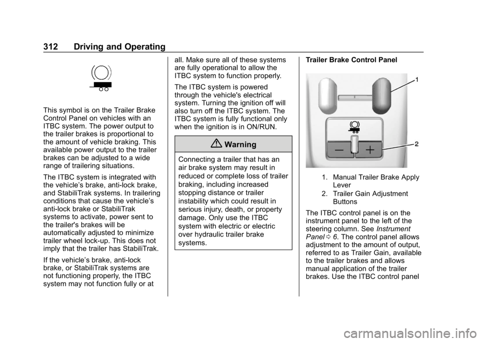
This symbol is on the Trailer Brake
Control Panel on vehicles with an
ITBC system. The power output to
the trailer brakes is proportional to
the amount of vehicle braking. This
available power output to the trailer
brakes can be adjusted to a wide
range of trailering situations.
The ITBC system is integrated with
the vehicle’s brake, anti-lock brake,
and StabiliTrak systems. In trailering
conditions that cause the vehicle’s
anti-lock brake or StabiliTrak
systems to activate, power sent to
the trailer's brakes will be
automatically adjusted to minimize
trailer wheel lock-up. This does not
imply that the trailer has StabiliTrak.
If the vehicle’s brake, anti-lock
brake, or StabiliTrak systems are
not functioning properly, the ITBC
system may not function fully or at all. Make sure all of these systems
are fully operational to allow the
ITBC system to function properly.
The ITBC system is powered
through the vehicle's electrical
system. Turning the ignition off will
also turn off the ITBC system. The
ITBC system is fully functional only
when the ignition is in ON/RUN.
{Warning
Connecting a trailer that has an
air brake system may result in
reduced or complete loss of trailer
braking, including increased
stopping distance or trailer
instability which could result in
serious injury, death, or property
damage. Only use the ITBC
system with electric or electric
over hydraulic trailer brake
systems.
Trailer Brake Control Panel
1. Manual Trailer Brake Apply
Lever
2. Trailer Gain Adjustment Buttons
The ITBC control panel is on the
instrument panel to the left of the
steering column. See Instrument
Panel 06. The control panel allows
adjustment to the amount of output,
referred to as Trailer Gain, available
to the trailer brakes and allows
manual application of the trailer
brakes. Use the ITBC control panel
Page 314 of 489
Chevrolet Silverado LD 1500 and Silverado 2500/3500 Owner Manual (GMNA-
Localizing-U.S./Canada-12162993) - 2019 - crc - 4/4/18
Driving and Operating 313
and the DIC trailer brake display
page to adjust and display power
output to the trailer brakes.
Trailer Brake DIC Display Page
The ITBC display page indicates
.Trailer Gain setting
. Output to the trailer brakes
. Trailer connection
. System operational status.
To display
. Scroll through the DIC menu
pages
. Press a Trailer Gain (+) or (−)
button
. Activate the Manual Trailer
Brake Apply Lever
Press a Trailer Gain button to recall
the current Trailer Gain setting.
Each press and release of the gain
buttons will then change the Trailer
Gain setting. TRAILER GAIN:
Press the Trailer Gain (+) or (−) to
adjust. Press and hold to
continuously adjust the Trailer Gain.
To turn the output to the trailer off,
adjust the Trailer Gain setting to 0.0.
This setting can be adjusted from
0.0 to 10.0 with a trailer connected
or disconnected.
TRAILER OUTPUT: This displays
anytime a trailer with electric brakes
is connected. Output to the trailer
brakes is based on the amount of
vehicle braking present and relative
to the Trailer Gain setting. Output is
displayed from 0 to 100% for each
gain setting.
The Trailer Output will indicate
“- - -
- - -” on the Trailer Brake Display
Page whenever the following occur:
. No trailer is connected.
. A trailer without electric brakes
is connected, no DIC message
will display .
A trailer with electric brakes has
become disconnected, a CHECK
TRAILER WIRING message
displays on the DIC
. There is a fault present in the
wiring to the trailer brakes, a
CHECK TRAILER WIRING
message displays on the DIC
. The ITBC system is not working
due to a fault, a SERVICE
TRAILER BRAKE SYSTEM
message displays in the DIC
Manual Trailer Brake Apply Lever
Slide this lever left to apply the
trailer ’s electric brakes independent
of the vehicle’s brakes. Use this
lever to adjust Trailer Gain to
achieve the proper power output to
the trailer brakes. The trailer's and
the vehicle's brake lamps will come
on when either vehicle brakes or
manual trailer brakes are applied
and properly connected.
Page 315 of 489
Chevrolet Silverado LD 1500 and Silverado 2500/3500 Owner Manual (GMNA-
Localizing-U.S./Canada-12162993) - 2019 - crc - 4/4/18
314 Driving and Operating
Trailer Gain Adjustment Procedure
Trailer Gain should be set for a
specific trailering condition and it
must be readjusted anytime vehicle
loading, trailer loading, or road
surface conditions change.
{Warning
Trailer brakes that are
over-gained or under-gained may
not stop the vehicle and the trailer
as intended and can result in a
crash. Always follow the
instructions to set the Trailer Gain
for the proper trailer stopping
performance.
To adjust Trailer Gain for each
towing condition: 1. Drive the vehicle with the trailer attached on a level road
surface representative of the
towing condition and free of
traffic at about 32 - 40 km/h
(20 - 25 mph) and fully apply
the Manual Trailer Brake Apply
Lever. Note
Adjusting Trailer Gain at speeds
lower than 32 to 40 km/h (20 to
25 mph) may result in an incorrect
gain setting.
2. Adjust the Trailer Gain, using the Trailer Gain (+) or (−)
adjustment Buttons, to just
below the point of trailer wheel
lock-up, indicated by trailer
wheel squeal or tire smoke
when a trailer wheel locks.
Note
Trailer wheel lock-up may not occur
if towing a heavily loaded trailer.
Adjust the Trailer Gain to the
highest allowable setting for the
towing condition.
3. Readjust Trailer Gain anytime vehicle loading, trailer loading,
or road surface conditions
change or if trailer wheel
lock-up is noticed at any time
while towing. Other ITBC-Related DIC Messages
TRAILER CONNECTED: This
message will briefly display when a
trailer with electric brakes is first
connected to the vehicle. This
message will automatically turn off
in about 10 seconds. This message
can be acknowledged before it
automatically turns off.
CHECK TRAILER WIRING: This
message will display if:
.
The ITBC system first
determines connection to a
trailer with electric brakes and
then the trailer harness becomes
disconnected the vehicle.
If the disconnect occurs while
the vehicle is stationary, this
message will automatically turn
off in about 30 seconds. This
message will also turn off if it is
acknowledged or if the trailer
harness is reconnected.
If the disconnect occurs while
the vehicle is moving, this
message will continue until the
ignition is turned off. This
Page 316 of 489
Chevrolet Silverado LD 1500 and Silverado 2500/3500 Owner Manual (GMNA-
Localizing-U.S./Canada-12162993) - 2019 - crc - 4/4/18
Driving and Operating 315
message will also turn off if it is
acknowledged or if the trailer
harness is reconnected.
. There is an electrical fault in the
wiring to the trailer brakes. This
message will continue as long
as there is an electrical fault in
the trailer wiring. This message
will also turn off if it is
acknowledged.
To determine whether the electrical
fault is on the vehicle side or trailer
side of the trailer wiring harness
connection: 1. Disconnect the trailer wiring harness from the vehicle.
2. Turn the ignition off.
3. Wait 10 seconds, then turn the ignition back to RUN.
4. If the CHECK TRAILER WIRING message reappears,
the electrical fault is on the
vehicle side. If the CHECK TRAILER WIRING
message only reappears when
connecting the trailer wiring harness
to the vehicle, the electrical fault is
on the trailer side.
SERVICE TRAILER BRAKE
SYSTEM: This message will display
when there is a problem with the
ITBC system. If this message
continues over multiple ignition
cycles, have the vehicle serviced.
If either the CHECK TRAILER
WIRING or SERVICE TRAILER
BRAKE SYSTEM message displays
while driving, the ITBC system may
not be fully functional or may not
function at all. When traffic
conditions allow, carefully pull the
vehicle over to the side of the road
and turn the ignition off. Check the
wiring connection to the trailer and
turn the ignition back on. If either of
these messages continues, either
the vehicle or trailer needs service.
A GM dealer may be able to
diagnose and repair problems with
the trailer. However, any diagnosis
and repair of the trailer is not
covered under the vehicle warranty. Contact your trailer dealer for
assistance with trailer repairs and
trailer warranty information.
Trailer Sway
Control (TSC)
Vehicles with StabiliTrak have a
Trailer Sway Control (TSC) feature.
Trailer sway is unintended
side-to-side motion of a trailer while
towing. If the vehicle is towing a
trailer and the TSC detects that
sway is increasing, the vehicle
brakes are selectively applied at
each wheel, to help reduce
excessive trailer sway. If equipped
with the Integrated Trailer Brake
Control (ITBC) system, and the
trailer has an electric brake system,
StabiliTrak may also apply the trailer
brakes.
Page 317 of 489
Chevrolet Silverado LD 1500 and Silverado 2500/3500 Owner Manual (GMNA-
Localizing-U.S./Canada-12162993) - 2019 - crc - 4/4/18
316 Driving and Operating
If TSC is enabled, the Traction
Control System (TCS)/StabiliTrak
warning light will flash on the
instrument cluster. Reduce vehicle
speed by gradually removing your
foot from the accelerator. If trailer
sway continues, StabiliTrak can
reduce engine torque to help slow
the vehicle. TSC will not function if
StabiliTrak is turned off. See
Traction Control/Electronic Stability
Control.
{Warning
Trailer sway can result in a crash
and in serious injury or death,
even if the vehicle is equipped
with TSC.(Continued)
Warning (Continued)
If the trailer begins to sway,
reduce vehicle speed by
gradually removing your foot from
the accelerator. Then pull over to
check the trailer and vehicle to
help correct possible causes,
including an improperly or
overloaded trailer, unrestrained
cargo, improper trailer hitch
configuration, or improperly
inflated or incorrect vehicle or
trailer tires. SeeTowing
Equipment 0306 for trailer ratings
and hitch setup
recommendations.
Aftermarket Electronic Trailer
Sway Control Devices
Some trailers may come equipped
with an electronic device designed
to reduce or control trailer sway.
Aftermarket equipment
manufacturers also offer similar
devices that connect to the wiring
between the trailer and the vehicle.
These devices may interfere with the vehicle’
s trailer brake systems
or other systems, including
integrated anti-sway systems,
if equipped. Messages related to
trailer connections or trailer brakes
could appear on the DIC. The
effects of these aftermarket devices
on vehicle handling or trailer brake
performance is not known.
{Warning
Use of aftermarket electronic
trailer sway control devices could
result in reduced trailer brake
performance, loss of trailer
brakes, or other malfunctions, and
result in a crash. You or others
could be seriously injured or
killed. Before using one of these
devices:
. Ask the device or trailer
manufacturer if the device
has been thoroughly tested
for compatibility with the
make, model, and year of
(Continued)
Page 318 of 489
Chevrolet Silverado LD 1500 and Silverado 2500/3500 Owner Manual (GMNA-
Localizing-U.S./Canada-12162993) - 2019 - crc - 4/4/18
Driving and Operating 317
Warning (Continued)
your vehicle and any
optional equipment installed
on your vehicle.
. Before driving, check the
trailer brakes are working
properly, if equipped. Drive
the vehicle with the trailer
attached on a level road
surface that is free of traffic
at about 32-40 km/h
(20-25 mph) and fully apply
the manual trailer brake
apply lever. Also, check the
trailer brake lamps and
other lamps are functioning
correctly.
. If the trailer brakes are not
operating properly at any
time, or if a DIC message
indicates problems with the
trailer connections or trailer
brakes, carefully pull the
vehicle over to the side of
the road when traffic
conditions allow.
Trailer Tires
Special Trailer (ST) tires differ from
vehicle tires. Trailer tires are
designed with stiff sidewalls to help
prevent sway and to support heavy
loads. These features can make it
difficult to determine if the trailer tire
pressures are low only based on a
visual inspection.
Always check all trailer tire
pressures before each trip when the
tires are cool. Low trailer tire
pressure is a leading cause of trailer
tire blow-outs.
Trailer tires deteriorate over time.
The trailer tire sidewall will show the
week and year the tire was
manufactured. Many trailer tire
manufacturers recommend
replacing tires more than six
years old.
Overloading is another leading
cause of trailer tire blow-outs. Never
load your trailer with more weight
than the tires are designed to
support. The load rating is located
on the trailer tire sidewall. Always know the maximum speed
rating for the trailer tires before
driving. This may be significantly
lower than the vehicle tire speed
rating. The speed rating may be on
the trailer tire sidewall. If the speed
rating is not shown, the default
trailer tire speed rating is 105 km/h
(65 mph).
Page 319 of 489
Chevrolet Silverado LD 1500 and Silverado 2500/3500 Owner Manual (GMNA-
Localizing-U.S./Canada-12162993) - 2019 - crc - 4/4/18
318 Driving and Operating
Conversions and
Add-Ons
Add-On Electrical
Equipment
{Warning
The Data Link Connector (DLC) is
used for vehicle service and
Emission Inspection/Maintenance
testing. SeeMalfunction Indicator
Lamp 0146. A device connected
to the DLC —such as an
aftermarket fleet or
driver-behavior tracking device —
may interfere with vehicle
systems. This could affect vehicle
operation and cause a crash.
Such devices may also access
information stored in the vehicle’s
systems.
Caution
Some electrical equipment can
damage the vehicle or cause
components to not work and
would not be covered by the
vehicle warranty. Always check
with your dealer before adding
electrical equipment.
Add-on equipment can drain the
vehicle's 12-volt battery, even if the
vehicle is not operating.
The vehicle has an airbag system.
Before attempting to add anything
electrical to the vehicle, see
Servicing the Airbag-Equipped
Vehicle 088 and Adding Equipment
to the Airbag-Equipped Vehicle
0 89.
For information on wiring auxiliary
switches, see www.gmupfitter.com
or contact your dealer.
Snow Plow Prep Wiring
Package
These wiring provisions are
included with RPO VYU (Snow Plow
Prep Package) only. These
provisions are for use with a snow
plow installed. The harness should
be installed by your dealer or
qualified service center.
Adding a Snow Plow or
Similar Equipment
Caution
Do not exceed 72 km/h (45 mph)
with a snow plow mounted to the
vehicle. The vehicle could
overheat and be damaged.
Page 320 of 489
Chevrolet Silverado LD 1500 and Silverado 2500/3500 Owner Manual (GMNA-
Localizing-U.S./Canada-12162993) - 2019 - crc - 4/4/18
Driving and Operating 319
Before installing a snow plow on the
vehicle, follow these guidelines:
Caution
If the vehicle does not have the
snow plow prep package, RPO
VYU, adding a plow can damage
the vehicle, and the repairs would
not be covered by the vehicle
warranty. Unless the vehicle was
built to carry a snow plow, do not
add one to the vehicle. If the
vehicle has RPO VYU, then the
payload the vehicle can carry will
be reduced when a snow plow is
installed. The vehicle can be
damaged if either the front or rear
axle ratings or the Gross Vehicle
Weight Rating (GVWR) are
exceeded.
The plow the vehicle can carry
depends on many things, such as:
. The options the vehicle came
with, and the weight of those
options. .
The weight and number of
passengers to be carried.
. The weight of items added to the
vehicle, like a tool box or
truck cap.
. The total weight of any
additional cargo to be carried.
For example, if the snow plow
weighs 318 kg (700 lb), the total
weight of all occupants and cargo
inside the cab should not exceed
135 kg (300 lb). This means that you
may only be able to carry one
passenger. Even this may be too
much if there is other equipment
already adding to the weight of the
vehicle.
To safely carry a snow plow on the
vehicle:
. Follow all aftermarket snow plow
manufacturer ’s instructions for
the operation and transportation
of the snow plow.
. With a snow plow attached, the
engine coolant temperature
gauge may show a higher
temperature than while driving without one. The snow plow
could block the airflow to the
radiator. This could be more
noticeable as vehicle speed
increases. At speeds above
72 km (45 mph), this may cause
the engine coolant to overheat.
. To increase the airflow, move the
snow plow blade postion.
. If driving more than 24 km
(15 mi), angle the plow blade
position.
. Make sure the weight on the
front and rear axles does not
exceed the axle rating for each.
. For the front axle, if more cargo
or passengers must be carried,
appropriate counter ballast must
be installed rear of the rear axle.
Counter ballast must be properly
secured so it will not move
during driving.
. Rear ballast may be required to
ensure a proper front and rear
weight distribution ratio, even
though the actual weight at the
front axle may be less than the
front axle rating.