CHEVROLET TAHOE 2003 2.G Owners Manual
Manufacturer: CHEVROLET, Model Year: 2003, Model line: TAHOE, Model: CHEVROLET TAHOE 2003 2.GPages: 552, PDF Size: 3.44 MB
Page 161 of 552
Sunroof
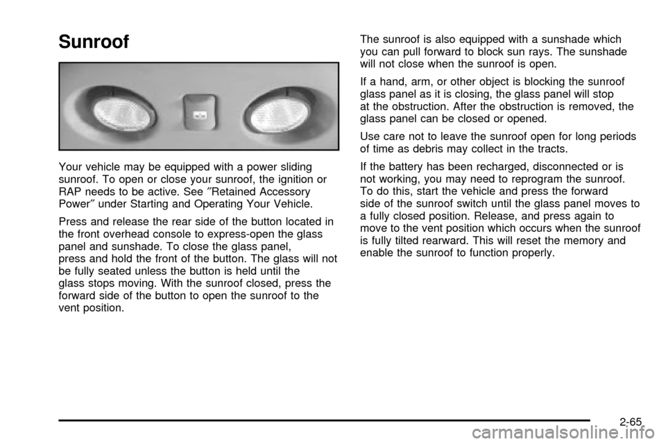
Your vehicle may be equipped with a power sliding
sunroof. To open or close your sunroof, the ignition or
RAP needs to be active. See²Retained Accessory
Power²under Starting and Operating Your Vehicle.
Press and release the rear side of the button located in
the front overhead console to express-open the glass
panel and sunshade. To close the glass panel,
press and hold the front of the button. The glass will not
be fully seated unless the button is held until the
glass stops moving. With the sunroof closed, press the
forward side of the button to open the sunroof to the
vent position.The sunroof is also equipped with a sunshade which
you can pull forward to block sun rays. The sunshade
will not close when the sunroof is open.
If a hand, arm, or other object is blocking the sunroof
glass panel as it is closing, the glass panel will stop
at the obstruction. After the obstruction is removed, the
glass panel can be closed or opened.
Use care not to leave the sunroof open for long periods
of time as debris may collect in the tracts.
If the battery has been recharged, disconnected or is
not working, you may need to reprogram the sunroof.
To do this, start the vehicle and press the forward
side of the sunroof switch until the glass panel moves to
a fully closed position. Release, and press again to
move to the vent position which occurs when the sunroof
is fully tilted rearward. This will reset the memory and
enable the sunroof to function properly.
2-65
Page 162 of 552
Vehicle Personalization
Memory Seat
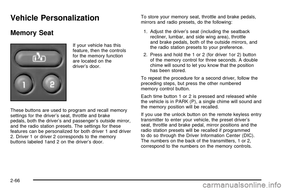
If your vehicle has this
feature, then the controls
for the memory function
are located on the
driver's door.
These buttons are used to program and recall memory
settings for the driver's seat, throttle and brake
pedals, both the driver's and passenger's outside mirror,
and the radio station presets. The settings for these
features can be personalized for both driver 1 and driver
2. Driver 1 or driver 2 corresponds to the memory
buttons labeled 1and 2 on the driver's door.To store your memory seat, throttle and brake pedals,
mirrors and radio presets, do the following:
1. Adjust the driver's seat (including the seatback
recliner, lumbar, and side wing area), throttle
and brake pedals, both of the outside mirrors, and
the radio station presets to your preference.
2. Press and hold the 1 or 2 (for driver 1or 2) button
of the memory control for three seconds. A double
chime will sound to let you know that the position
has been stored.
To repeat the procedure for a second driver, follow the
preceding steps, but press the other numbered
memory control button.
Each time button 1 or 2 is pressed and released while
the vehicle is in PARK (P), a single chime will sound and
the memory position will be recalled.
If you use the unlock button on the remote keyless entry
transmitter to enter your vehicle, the preset driver's
seat, throttle and brake pedal, mirror positions and the
radio station presets will be recalled if programmed
to do so through the Driver Information Center (DIC).
The numbers on the back of the transmitters, 1 or 2,
correspond to the numbers on the memory controls.
2-66
Page 163 of 552

The seat, throttle and brake pedals and mirror positions
can also be recalled when placing the key in the
ignition if programmed to do so through the Driver
Information Center (DIC).
To stop recall movement of the memory seat feature at
any time, press one of the memory buttons or power
seat controls.
Easy Exit Seat
The controls for this memory function are located on the
driver's door.
BThis button is used to program and recall the
desired driver's seat position when exiting/entering the
vehicle. The seat position, can be personalized for
both driver 1 and driver 2.
To store the seat exit position for driver 1 or 2, do the
following:
1. Select the desired driver number by pressing and
releasing the 1 or 2 button. The seat will move to
the stored memory position.
2. Adjust the seat to the desired exit position.3. Press and hold the exit button of the memory
control for three seconds. A double chime will sound
to let you know that the position has been stored
for the identi®ed driver (1 or 2).
To use the seat exit position, do one of the following:
·Press the exit button on the memory control.
·Or, if this feature is enabled (active) in the DIC,
then removing the key from the ignition will
cause the seat to move to the exit position.
2-67
Page 164 of 552
-NOTES
2-68
Page 165 of 552

Instrument Panel Overview...............................3-4
Hazard Warning Flashers................................3-6
Other Warning Devices...................................3-6
Horn.............................................................3-7
Tilt Wheel.....................................................3-7
Turn Signal/Multifunction Lever.........................3-7
Exterior Lamps.............................................3-14
Interior Lamps..............................................3-17
Accessory Power Outlets...............................3-19
Ashtrays and Cigarette Lighter........................3-20
Climate Controls............................................3-20
Climate Control System.................................3-20
Dual Climate Control System..........................3-21
Dual Automatic Climate Control System...........3-25
Rear Air Conditioning System.........................3-31
Rear Air Conditioning and Heating System.......3-32
Rear Air Conditioning and Heating System and
Electronic Climate Controls.........................3-34
Warning Lights, Gages and Indicators.............3-36
Instrument Panel Cluster................................3-37
Speedometer and Odometer...........................3-38
Tachometer.................................................3-38Safety Belt Reminder Light.............................3-38
Air Bag Readiness Light................................3-39
Passenger Air Bag Status Indicator.................3-39
Battery Warning Light....................................3-41
Voltmeter Gage............................................3-42
Brake System Warning Light..........................3-42
Anti-Lock Brake System Warning Light.............3-44
Traction Off Light..........................................3-44
Engine Coolant Temperature Gage..................3-45
Transmission Temperature Gage.....................3-46
Malfunction Indicator Lamp.............................3-47
Oil Pressure Gage........................................3-50
Cruise Control Light......................................3-51
Four-Wheel-Drive Light..................................3-51
Tow/Haul Mode Light....................................3-52
Fuel Gage...................................................3-52
Low Fuel Warning Light.................................3-53
Driver Information Center (DIC).......................3-53
DIC Operation and Displays...........................3-54
DIC Warnings and Messages.........................3-64
Section 3 Instrument Panel
3-1
Page 166 of 552

Audio System(s).............................................3-72
Setting the Time for Radios without Radio
Data Systems (RDS)..................................3-72
Setting the Time for Radios with Radio Data
Systems (RDS).........................................3-73
AM-FM Radio...............................................3-73
Radio with CD..............................................3-76
Radio with Cassette and CD..........................3-87
Radio with Six-Disc CD................................3-101
Rear Seat Entertainment System...................3-114
Rear Seat Audio (RSA)................................3-124
Theft-Deterrent Feature................................3-125Audio Steering Wheel Controls......................3-126
DVD Distortion............................................3-126
Understanding Radio Reception....................3-127
Care of Your Cassette Tape Player...............3-127
Care of Your CDs and DVDs........................3-128
Care of Your CD and DVD Player.................3-129
Cleaning the Video Screen...........................3-129
Fixed Mast Antenna....................................3-129
XMŸ Satellite Radio Antenna System
(48 Contiguous US States)........................3-129
Chime Level Adjustment...............................3-129
Section 3 Instrument Panel
3-2
Page 167 of 552
-NOTES
3-3
Page 168 of 552

Instrument Panel Overview
3-4
Page 169 of 552

A. Dome Lamp Override Button. See ªDome Lampsº
underInterior Lamps on page 3-17.
B. Exterior Lamp Controls. See
Exterior Lamps on
page 3-14.
C. Air Outlets. See ªClimate Controlsº in Section 3.
D. Automatic Transfer Case/Stabilitrak
žMode Button
(AWD Vehicles)/Traction Assist System (TAS).
See
Four-Wheel Drive on page 2-29.
E. Turn Signal/Multifunction Lever. See
Turn
Signal/Multifunction Lever on page 3-7.
F. Instrument Panel Cluster. See
Instrument Panel
Cluster on page 3-37.
G. Gearshift Lever. See
Automatic Transmission
Operation on page 2-26.
H. Tow/Haul Selector Button (If Equipped). See
Automatic Transmission Operation on page 2-26.
I. Audio System. See
Audio System(s) on page 3-72.
J. Comfort Control System. See
Climate Control
System on page 3-20.K. Instrument Panel Fuse Block. See
Fuses and Circuit
Breakers on page 5-109.
L. Hood Release. See
Hood Release on page 5-12.
M. Steering Wheel Control Buttons (If Equipped).
See
Driver Information Center (DIC) on page 3-53.
N. Center Instrument Panel Utility Block. See
Fuses and
Circuit Breakers on page 5-109.
O. Tilt Wheel Lever. See
Tilt Wheel on page 3-7.
P. Parking Brake Release. See
Parking Brake on
page 2-38.
Q. Lighter and Accessory Power Outlets. See
Accessory Power Outlets on page 3-19.
R. Storage Area (If Equipped). See ªStorage Areasº in
Section 2.
S. Ashtray. See
Ashtrays and Cigarette Lighter on
page 3-20.
T. Glovebox. See
Glove Box on page 2-61.
3-5
Page 170 of 552
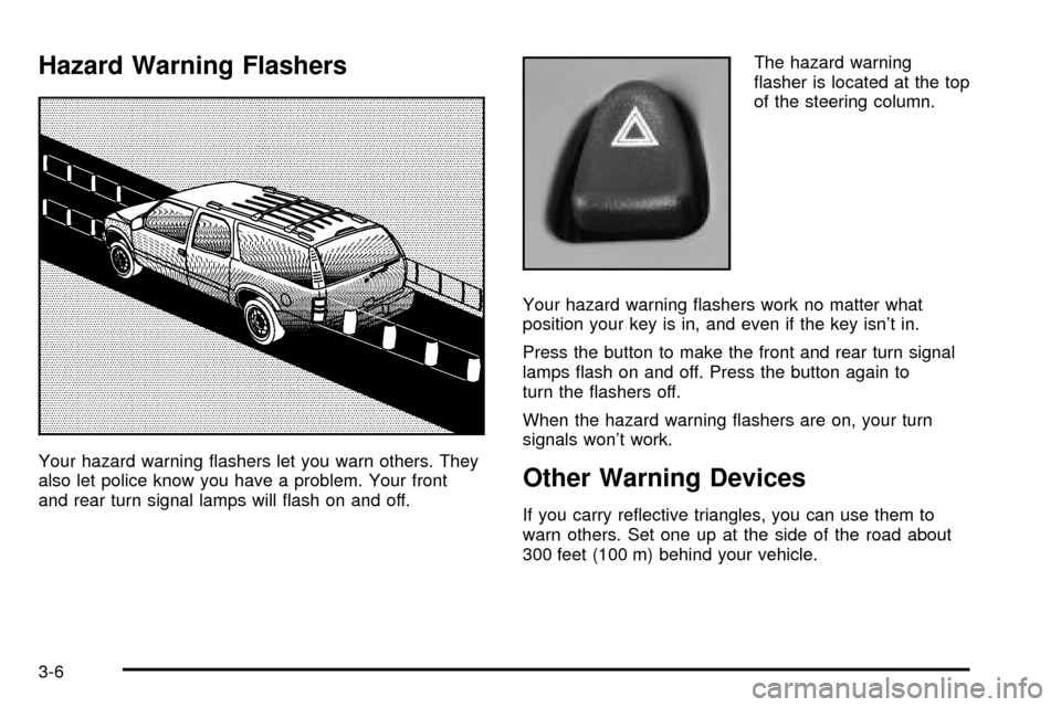
Hazard Warning Flashers
Your hazard warning ¯ashers let you warn others. They
also let police know you have a problem. Your front
and rear turn signal lamps will ¯ash on and off.The hazard warning
¯asher is located at the top
of the steering column.
Your hazard warning ¯ashers work no matter what
position your key is in, and even if the key isn't in.
Press the button to make the front and rear turn signal
lamps ¯ash on and off. Press the button again to
turn the ¯ashers off.
When the hazard warning ¯ashers are on, your turn
signals won't work.Other Warning Devices
If you carry re¯ective triangles, you can use them to
warn others. Set one up at the side of the road about
300 feet (100 m) behind your vehicle.
3-6