CHEVROLET TAHOE 2006 2.G Owners Manual
Manufacturer: CHEVROLET, Model Year: 2006, Model line: TAHOE, Model: CHEVROLET TAHOE 2006 2.GPages: 540, PDF Size: 3.06 MB
Page 461 of 540
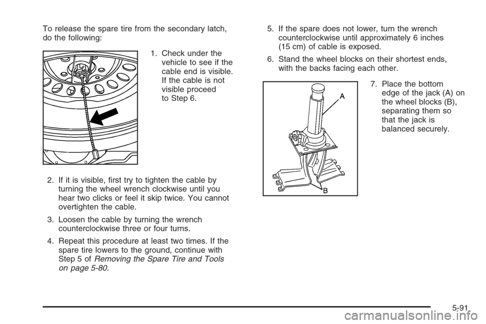
To release the spare tire from the secondary latch,
do the following:
1. Check under the
vehicle to see if the
cable end is visible.
If the cable is not
visible proceed
to Step 6.
2. If it is visible, �rst try to tighten the cable by
turning the wheel wrench clockwise until you
hear two clicks or feel it skip twice. You cannot
overtighten the cable.
3. Loosen the cable by turning the wrench
counterclockwise three or four turns.
4. Repeat this procedure at least two times. If the
spare tire lowers to the ground, continue with
Step 5 ofRemoving the Spare Tire and Tools
on page 5-80.5. If the spare does not lower, turn the wrench
counterclockwise until approximately 6 inches
(15 cm) of cable is exposed.
6. Stand the wheel blocks on their shortest ends,
with the backs facing each other.
7. Place the bottom
edge of the jack (A) on
the wheel blocks (B),
separating them so
that the jack is
balanced securely.
5-91
Page 462 of 540
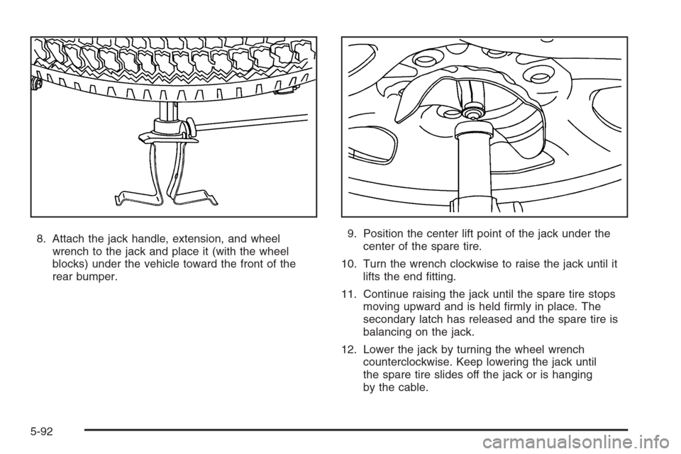
8. Attach the jack handle, extension, and wheel
wrench to the jack and place it (with the wheel
blocks) under the vehicle toward the front of the
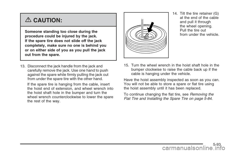
rear bumper.9. Position the center lift point of the jack under the
center of the spare tire.
10. Turn the wrench clockwise to raise the jack until it
lifts the end �tting.
11. Continue raising the jack until the spare tire stops
moving upward and is held �rmly in place. The
secondary latch has released and the spare tire is
balancing on the jack.
12. Lower the jack by turning the wheel wrench
counterclockwise. Keep lowering the jack until
the spare tire slides off the jack or is hanging
by the cable.
5-92
Page 463 of 540
{CAUTION:
Someone standing too close during the
procedure could be injured by the jack.
If the spare tire does not slide off the jack
completely, make sure no one is behind you
or on either side of you as you pull the jack
out from the spare.
13. Disconnect the jack handle from the jack and
carefully remove the jack. Use one hand to push
against the spare while �rmly pulling the jack out
from under the spare tire with the other hand.
If the spare tire is hanging from the cable, insert
the hoist end of extension, and wheel wrench into
the hoist shaft hole in the bumper and turn the
wheel wrench counterclockwise to lower the spare
the rest of the way.14. Tilt the tire retainer (G)
at the end of the cable
and pull it through
the wheel opening.
Pull the tire out
from under the vehicle.
15. Turn the wheel wrench in the hoist shaft hole in the
bumper clockwise to raise the cable back up if the
cable is hanging under the vehicle.
Have the hoist assembly inspected as soon as you can.
You will not be able to store a spare or �at tire using
the hoist assembly until it has been replaced.
To continue changing the �at tire, seeRemoving the
Flat Tire and Installing the Spare Tire on page 5-84.
5-93
Page 464 of 540
Storing a Flat or Spare Tire
and Tools
{CAUTION:
Storing a jack, a tire, or other equipment in the
passenger compartment of the vehicle could
cause injury. In a sudden stop or collision,
loose equipment could strike someone.
Store all these in the proper place.
Notice:Storing an aluminum wheel with a �at tire
under your vehicle for an extended period of time or
with the valve stem pointing up may damage the
wheel. Always stow the wheel with the valve stem
pointing down and have the wheel/tire repaired as
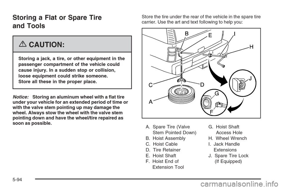
soon as possible.Store the tire under the rear of the vehicle in the spare tire
carrier. Use the art and text following to help you:
A. Spare Tire (Valve
Stem Pointed Down)
B. Hoist Assembly
C. Hoist Cable
D. Tire Retainer
E. Hoist Shaft
F. Hoist End of
Extension ToolG. Hoist Shaft
Access Hole
H. Wheel Wrench
I. Jack Handle
Extensions
J. Spare Tire Lock
(If Equipped)
5-94
Page 465 of 540
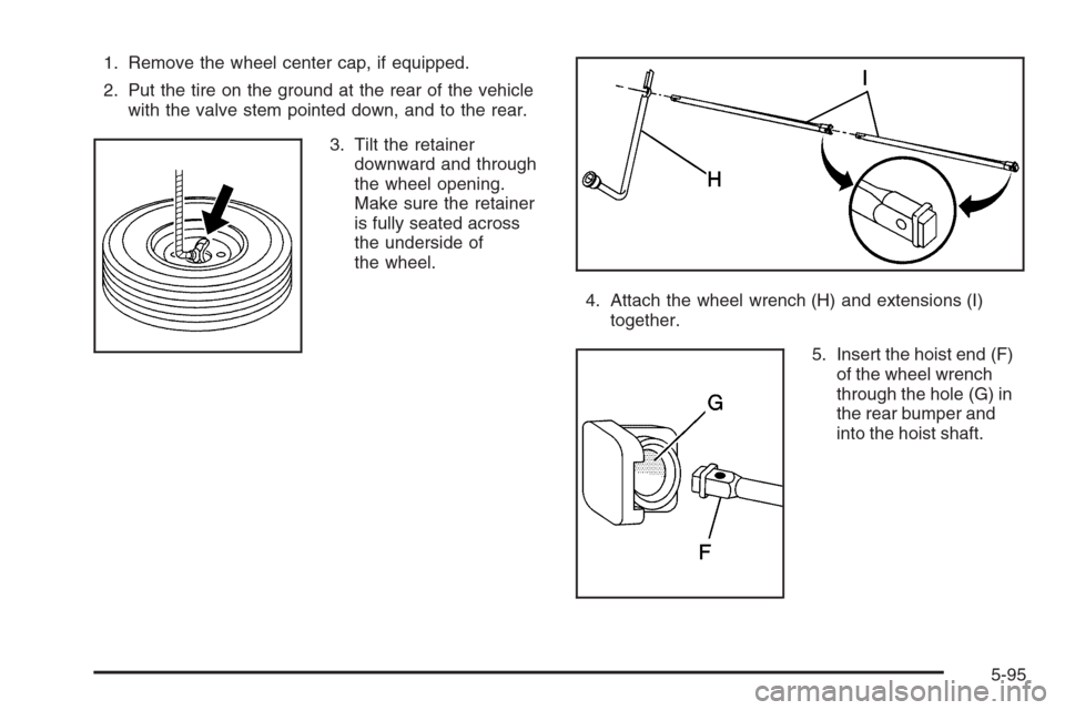
1. Remove the wheel center cap, if equipped.
2. Put the tire on the ground at the rear of the vehicle
with the valve stem pointed down, and to the rear.
3. Tilt the retainer
downward and through
the wheel opening.
Make sure the retainer
is fully seated across
the underside of
the wheel.
4. Attach the wheel wrench (H) and extensions (I)
together.
5. Insert the hoist end (F)
of the wheel wrench
through the hole (G) in
the rear bumper and
into the hoist shaft.
5-95
Page 466 of 540
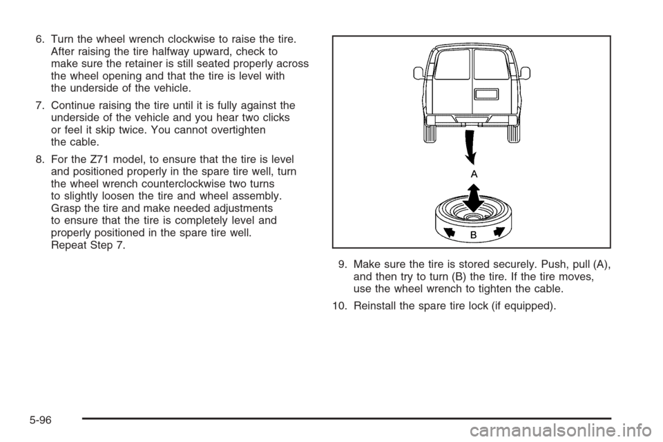
6. Turn the wheel wrench clockwise to raise the tire.
After raising the tire halfway upward, check to
make sure the retainer is still seated properly across
the wheel opening and that the tire is level with
the underside of the vehicle.
7. Continue raising the tire until it is fully against the
underside of the vehicle and you hear two clicks
or feel it skip twice. You cannot overtighten
the cable.
8. For the Z71 model, to ensure that the tire is level
and positioned properly in the spare tire well, turn
the wheel wrench counterclockwise two turns
to slightly loosen the tire and wheel assembly.
Grasp the tire and make needed adjustments
to ensure that the tire is completely level and
properly positioned in the spare tire well.
Repeat Step 7.
9. Make sure the tire is stored securely. Push, pull (A),
and then try to turn (B) the tire. If the tire moves,
use the wheel wrench to tighten the cable.
10. Reinstall the spare tire lock (if equipped).
5-96
Page 467 of 540
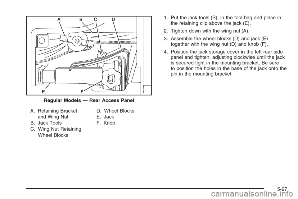
A. Retaining Bracket
and Wing Nut
B. Jack Tools
C. Wing Nut Retaining
Wheel BlocksD. Wheel Blocks
E. Jack
F. Knob1. Put the jack tools (B), in the tool bag and place in
the retaining clip above the jack (E).
2. Tighten down with the wing nut (A).
3. Assemble the wheel blocks (D) and jack (E)
together with the wing nut (D) and knob (F).
4. Position the jack storage cover in the left rear side
panel and tighten, adjusting clockwise until the jack
is secured tight in the mounting bracket. Be sure
to position the holes in the base of the jack onto the
pin in the mounting bracket.
Regular Models — Rear Access Panel
5-97
Page 468 of 540
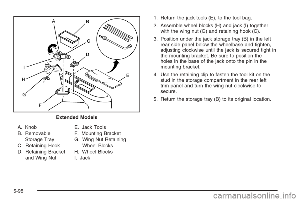
A. Knob
B. Removable
Storage Tray
C. Retaining Hook
D. Retaining Bracket
and Wing NutE. Jack Tools
F. Mounting Bracket
G. Wing Nut Retaining
Wheel Blocks
H. Wheel Blocks
I. Jack1. Return the jack tools (E), to the tool bag.
2. Assemble wheel blocks (H) and jack (I) together
with the wing nut (G) and retaining hook (C).
3. Position under the jack storage tray (B) in the left
rear side panel below the wheelbase and tighten,
adjusting clockwise until the jack is secured tight in
the mounting bracket. Be sure to position the
holes in the base of the jack onto the pin in the
mounting bracket.
4. Use the retaining clip to fasten the tool kit on the
stud in the storage compartment in the rear left
trim panel and turn the wing nut clockwise to
secure.
5. Return the storage tray (B) to its original location.
Extended Models
5-98
Page 469 of 540
Spare Tire
Your vehicle, when new, had a fully-in�ated spare tire.
A spare tire may lose air over time, so check its
in�ation pressure regularly. SeeIn�ation - Tire Pressure
on page 5-65andLoading Your Vehicle on page 4-48
for information regarding proper tire in�ation and loading
your vehicle. For instruction on how to remove, install
or store a spare tire, seeRemoving the Flat Tire
and Installing the Spare Tire on page 5-84andStoring
a Flat or Spare Tire and Tools on page 5-94.
Your vehicle may have a different size spare tire than
the road tires originally installed on your vehicle.
This spare tire was developed for use on your vehicle,
so it is all right to drive on it. If your vehicle has
four-wheel drive and the different size spare tire is
installed, keep the vehicle in two-wheel drive.
Notice:If your vehicle has four-wheel drive and the
different size spare tire is installed on your vehicle,
do not drive in four-wheel drive until you can
have your �at tire repaired and/or replaced. You
could damage your vehicle, and the repair costs
would not be covered by your warranty. Never use
four-wheel drive when the different size spare
tire is installed on your vehicle.After installing the spare tire on your vehicle, you should
stop as soon as possible and make sure the spare
tire is correctly in�ated. Have the damaged or �at road
tire repaired or replaced as soon as you can and
installed back onto your vehicle. This way, the spare tire
will be available in case you need it again.
Do not mix tires and wheels of different sizes, because
they will not �t. Keep your spare tire and its wheel
together. If your vehicle has a spare tire that does not
match your vehicle’s original road tires and wheels
in size and type, do not include the spare in the
tire rotation.
Appearance Care
Cleaning the Inside of Your Vehicle
Your vehicle’s interior will continue to look its best if
it is cleaned often. Although not always visible, dust
and dirt can accumulate on your upholstery. Dirt
can damage carpet, fabric, leather, and plastic surfaces.
Regular vacuuming is recommended to remove
particles from your upholstery. It is important to keep
your upholstery from becoming and remaining heavily
soiled. Soils should be removed as quickly as possible.
Your vehicle’s interior may experience extremes of
heat that could cause stains to set rapidly.
5-99
Page 470 of 540
Lighter colored interiors may require more frequent
cleaning. Use care because newspapers and garments
that transfer color to your home furnishings may also
transfer color to your vehicle’s interior.
When cleaning your vehicle’s interior, only use cleaners
speci�cally designed for the surfaces being cleaned.
Permanent damage may result from using cleaners on
surfaces for which they were not intended. Use glass
cleaner only on glass. Remove any accidental over-spray
from other surfaces immediately. To prevent over-spray,
apply cleaner directly to the cleaning cloth.
Notice:If you use abrasive cleaners when cleaning
glass surfaces on your vehicle, you could scratch
the glass and/or cause damage to the rear window
defogger. When cleaning the glass on your
vehicle, use only a soft cloth and glass cleaner.
Many cleaners contain solvents that may become
concentrated in your vehicle’s breathing space. Before
using cleaners, read and adhere to all safety
instructions on the label. While cleaning your vehicle’s
interior, maintain adequate ventilation by opening
your vehicle’s doors and windows.
Dust may be removed from small buttons and knobs
using a small brush with soft bristles.
Your GM dealer has a product for cleaning your
vehicle’s glass. Should it become necessary, you can
also obtain a product from your GM dealer to remove
odors from your vehicle’s upholstery.Do not clean your vehicle using the following cleaners
or techniques:
Never use a knife or any other sharp object to
remove a soil from any interior surface.
Never use a stiff brush. It can cause damage to
your vehicle’s interior surfaces.
Never apply heavy pressure or rub aggressively
with a cleaning cloth. Use of heavy pressure
can damage your interior and does not improve the
effectiveness of soil removal.
Use only mild, neutral-pH soaps. Avoid laundry
detergents or dishwashing soaps with degreasers.
Using too much soap will leave a residue that
leaves streaks and attracts dirt. For liquid cleaners,
about 20 drops per gallon (3.78 L) of water is a
good guide.
Do not heavily saturate your upholstery while
cleaning.
Damage to your vehicle’s interior may result from
the use of many organic solvents such as naptha,
alcohol, etc.
5-100