fuse CHEVROLET TAHOE 2010 3.G Owners Manual
[x] Cancel search | Manufacturer: CHEVROLET, Model Year: 2010, Model line: TAHOE, Model: CHEVROLET TAHOE 2010 3.GPages: 608, PDF Size: 6.53 MB
Page 42 of 608
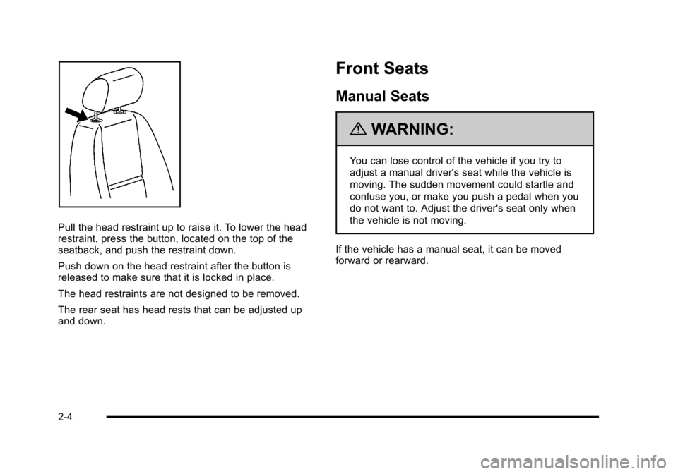
Pull the head restraint up to raise it. To lower the head
restraint, press the button, located on the top of the
seatback, and push the restraint down.
Push down on the head restraint after the button is
released to make sure that it is locked in place.
The head restraints are not designed to be removed.
The rear seat has head rests that can be adjusted up
and down.
Front Seats
Manual Seats
{WARNING:
You can lose control of the vehicle if you try to
adjust a manual driver's seat while the vehicle is
moving. The sudden movement could startle and
confuse you, or make you push a pedal when you
do not want to. Adjust the driver's seat only when
the vehicle is not moving.
If the vehicle has a manual seat, it can be moved
forward or rearward.
2-4
Page 50 of 608
Reclining Seatbacks
{WARNING:
You can lose control of the vehicle if you try to
adjust a manual driver's seat while the vehicle is
moving. The sudden movement could startle and
confuse you, or make you push a pedal when you
do not want to. Adjust the driver's seat only when
the vehicle is not moving.
{WARNING:
If either seatback is not locked, it could move
forward in a sudden stop or crash. That could
cause injury to the person sitting there. Always
push and pull on the seatbacks to be sure they
are locked.
2-12
Page 163 of 608

The theft-deterrent system will not activate if the doors
are locked with the vehicle's key or the manual door
lock. It activates only if you use the power door lock
switch with the door open or the RKE transmitter. You
should also remember that you can start your vehicle
with the correct ignition key if the alarm has been
set off.
To avoid setting off the alarm by accident:
.If you do not want to activate the theft-deterrent
system, the vehicle should be locked with the door
key after the doors are closed.
.Always unlock the doors with the RKE transmitter.
Unlocking a door any other way will set off the
alarm if it is armed.
If you set off the alarm by accident, press unlock on the
RKE transmitter or place the key in the ignition and turn
it to START to turn off the alarm. The alarm will not stop
if you try to unlock a door any other way.
Testing the Alarm
To test the alarm: 1. From inside the vehicle, lower the driver's window and open the driver's door.
2. Activate the system by locking the doors with the power door lock switch while the door is open,
or with the RKE transmitter.
3. Get out of the vehicle, close the door and wait for the security light to go out.
4. Then reach in through the window, unlock the door with the manual door lock and open the door. This
should set off the alarm.
While the alarm is set, the power door unlock switch will
not work.
If the alarm does not sound when it should but the
headlamps flash, check to see if the horn works. The
horn fuse may be blown. To replace the fuse, see Fuses
and Circuit Breakers on page 6‑118.
If the alarm does not sound or the headlamps do not
flash, the vehicle should be serviced by your dealer.
3-23
Page 164 of 608

PASS-Key®III+ Electronic
Immobilizer
See Radio Frequency Statementon page 8‑19for
information regarding Part 15 of the Federal
Communications Commission (FCC) Rules and
RSS-210/211 of Industry Canada.
PASS-Key®III+ Electronic
Immobilizer Operation
Your vehicle has PASS-Key®III+ (Personalized
Automotive Security System) theft-deterrent system.
PASS-Key
®III+ is a passive theft-deterrent system.
The system is automatically armed when the key is
removed from the ignition.
The system is automatically disarmed when the key is
turned to ON/RUN, ACC/ACCESSORY or START from
the LOCK/OFF position.
You do not have to manually arm or disarm the system. The security light will come on if there is a problem with
arming or disarming the theft-deterrent system.
When the PASS-Key
®III+ system senses that someone
is using the wrong key, it prevents the vehicle from
starting. Anyone using a trial-and-error method to start
the vehicle will be discouraged because of the high
number of electrical key codes.
If the engine does not start and the security light on
the instrument panel cluster comes on when trying to
start the vehicle, there may be a problem with your
theft-deterrent system. Turn the ignition off and try
again.
If the engine still does not start, and the key appears to
be undamaged, try another ignition key. At this time,
you may also want to check the fuse, see Fuses and
Circuit Breakers
on page 6‑118. If the engine still does
not start with the other key, your vehicle needs service.
If your vehicle does start, the first key may be faulty.
See your dealer who can service the PASS-Key
®III+ to
have a new key made. In an emergency, contact
Roadside Assistance.
3-24
Page 170 of 608
Adjustable Throttle and Brake Pedal
On vehicles with this feature, you can change the
position of the throttle and brake pedals.
No adjustment to the pedals can be made when the
vehicle is in R (Reverse) or while using the cruise
control.
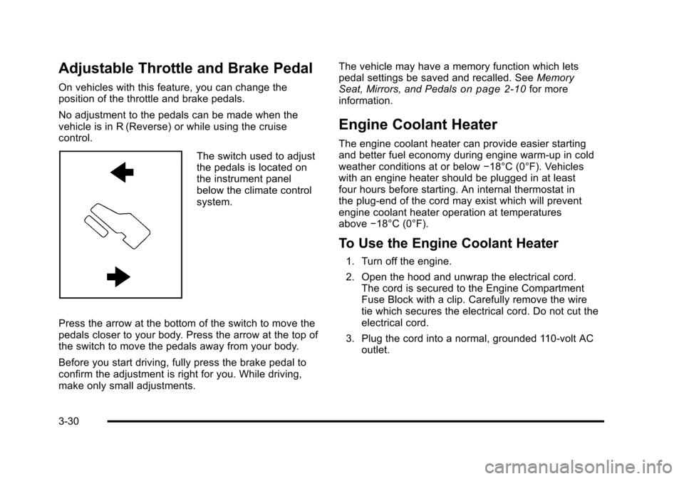
The switch used to adjust
the pedals is located on
the instrument panel
below the climate control
system.
Press the arrow at the bottom of the switch to move the
pedals closer to your body. Press the arrow at the top of
the switch to move the pedals away from your body.
Before you start driving, fully press the brake pedal to
confirm the adjustment is right for you. While driving,
make only small adjustments. The vehicle may have a memory function which lets
pedal settings be saved and recalled. See
Memory
Seat, Mirrors, and Pedals
on page 2‑10for more
information.
Engine Coolant Heater
The engine coolant heater can provide easier starting
and better fuel economy during engine warm-up in cold
weather conditions at or below −18°C (0°F). Vehicles
with an engine heater should be plugged in at least
four hours before starting. An internal thermostat in
the plug-end of the cord may exist which will prevent
engine coolant heater operation at temperatures
above −18°C (0°F).
To Use the Engine Coolant Heater
1. Turn off the engine.
2. Open the hood and unwrap the electrical cord.
The cord is secured to the Engine Compartment
Fuse Block with a clip. Carefully remove the wire
tie which secures the electrical cord. Do not cut the
electrical cord.
3. Plug the cord into a normal, grounded 110-volt AC outlet.
3-30
Page 222 of 608

Turn Signal/Multifunction Lever
The lever on the left side of the steering column
includes the following:
G:Turn and Lane Change Signals
5 3:Headlamp High/Low-Beam Changer
N:Windshield Wipers
L:Windshield Washer
5:Rear Wiper Delay
Z:Rear Wiper
=:Rear Wiper Wash
Flash-to-Pass.
Information for these features is on the pages following.
Turn and Lane-Change Signals
An arrow on the
instrument panel cluster
flashes in the direction of
the turn or lane change.
Move the lever all the way up or down to signal a turn.
Raise or lower the lever for less than one second
until the arrow starts to flash to signal a lane change.
This causes the turn signals to automatically flash
three times. It will flash six times if tow-haul mode is
active. Holding the turn signal lever for more than
one second will cause the turn signals to flash until
you release the lever.
The lever returns to its starting position whenever it is
released.
If after signaling a turn or a lane change the arrows
flash rapidly or do not come on, a signal bulb could be
burned out.
Have the bulbs replaced. If the bulb is not burned out,
check the fuse. See Fuses and Circuit Breakers
on
page 6‑118.
4-4
Page 232 of 608
Auxiliary Roof-Mounted Lamp
If the vehicle has this feature, this button includes wiring
provisions for a dealer or a qualified service center to
install an auxiliary roof lamp.
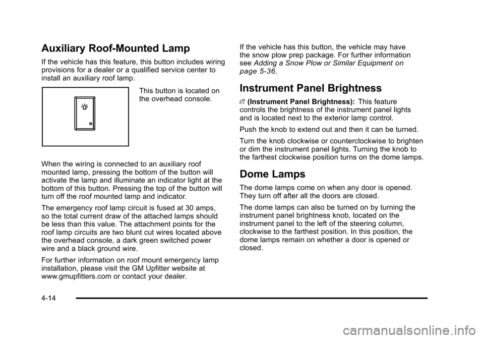
This button is located on
the overhead console.
When the wiring is connected to an auxiliary roof
mounted lamp, pressing the bottom of the button will
activate the lamp and illuminate an indicator light at the
bottom of this button. Pressing the top of the button will
turn off the roof mounted lamp and indicator.
The emergency roof lamp circuit is fused at 30 amps,
so the total current draw of the attached lamps should
be less than this value. The attachment points for the
roof lamp circuits are two blunt cut wires located above
the overhead console, a dark green switched power
wire and a black ground wire.
For further information on roof mount emergency lamp
installation, please visit the GM Upfitter website at
www.gmupfitters.com or contact your dealer. If the vehicle has this button, the vehicle may have
the snow plow prep package. For further information
see
Adding a Snow Plow or Similar Equipment
on
page 5‑36.
Instrument Panel Brightness
D (Instrument Panel Brightness): This feature
controls the brightness of the instrument panel lights
and is located next to the exterior lamp control.
Push the knob to extend out and then it can be turned.
Turn the knob clockwise or counterclockwise to brighten
or dim the instrument panel lights. Turning the knob to
the farthest clockwise position turns on the dome lamps.
Dome Lamps
The dome lamps come on when any door is opened.
They turn off after all the doors are closed.
The dome lamps can also be turned on by turning the
instrument panel brightness knob, located on the
instrument panel to the left of the steering column,
clockwise to the farthest position. In this position, the
dome lamps remain on whether a door is opened or
closed.
4-14
Page 235 of 608
Certain accessory plugs may not be compatible to the
accessory power outlet and could result in blown
adapter or vehicle fuses. If you experience a problem,
see your dealer for additional information on the
accessory power plugs.
Notice:Adding any electrical equipment to the
vehicle can damage it or keep other components
from working as they should. The repairs would not
be covered by the vehicle warranty. Do not use
equipment exceeding maximum amperage rating of
20 amperes. Check with your dealer before adding
electrical equipment.
When adding electrical equipment, be sure to follow
the proper installation instructions included with the
equipment. Do not use equipment exceeding the
maximum amperage rating of 20 amperes.
Notice: Improper use of the power outlet can cause
damage not covered by the vehicle warranty. Do not
hang any type of accessory or accessory bracket
from the plug because the power outlets are
designed for accessory power plugs only.Ashtray(s) and Cigarette Lighter
The front ashtray is located near the center of the
instrument panel or on the front console, if equipped.
Pull on the ashtray door to open it.
Notice: If papers, pins, or other flammable items are
put in the ashtray, hot cigarettes or other smoking
materials could ignite them and possibly damage
the vehicle. Never put flammable items in the
ashtray.
To remove the front ashtray pull the ashtray up.
To use the cigarette lighter, push it in all the way, and let
go. When it is ready, it will pop back out by itself.
Notice: Holding a cigarette lighter in while it is
heating does not let the lighter back away from the
heating element when it is hot. Damage from
overheating can occur to the lighter or heating
element, or a fuse could be blown. Do not hold a
cigarette lighter in while it is heating.
4-17
Page 371 of 608
Loading Your Vehicle for Off-Road
Driving
{WARNING:
.Cargo on the load floor piled higher than the
seatbacks can be thrown forward during a
sudden stop. You or your passengers could
be injured. Keep cargo below the top of the
seatbacks.
.Unsecured cargo on the load floor can be
tossed about when driving over rough terrain.
You or your passengers can be struck by
flying objects. Secure the cargo properly.
.Heavy loads on the roof raise the vehicle's
center of gravity, making it more likely to roll
over. You can be seriously or fatally injured if
the vehicle rolls over. Put heavy loads inside
the cargo area, not on the roof. Keep cargo in
the cargo area as far forward and low as
possible.There are some important things to remember about
how to load your vehicle.
.The heaviest things should be on the floor, forward
of the rear axle. Put heavier items as far forward
as you can.
.Be sure the load is properly secured, so things are
not tossed around.
You will find other important information under Loading
the Vehicle
on page 5‑29and Tires on page 6‑63.
Environmental Concerns
Off-road driving can provide wholesome and satisfying
recreation. However, it also raises environmental
concerns. We recognize these concerns and urge every
off-roader to follow these basic rules for protecting the
environment:
.Always use established trails, roads, and areas
that have been specially set aside for public
off-road recreational driving and obey all posted
regulations.
.Avoid any driving practice that could damage
shrubs, flowers, trees, or grasses or disturb
wildlife. This includes wheel-spinning, breaking
down trees, or unnecessary driving through
streams or over soft ground.
.Always carry a litter bag and make sure all refuse
is removed from any campsite before leaving.
5-13
Page 423 of 608
Leaving After Parking on a Hill
1. Apply and hold the brake pedal.
2. Start the engine
3. Shift into a gear
4. Release the parking brake
5. Let up on the brake pedal.
6. Drive slowly until the trailer is clear of the chocks.
7. Stop and have someone pick up and store thechocks.
Maintenance When Trailer Towing
The vehicle needs service more often when pulling a
trailer. See this manual's Maintenance Schedule or
Index for more information. Things that are especially
important in trailer operation are automatic transmission
fluid, engine oil, axle lubricant, belts, cooling system
and brake system. It is a good idea to inspect these
before and during the trip.
Check periodically to see that all hitch nuts and bolts
are tight.
Trailer Wiring Harness
The vehicle is equipped with the following wiring
harnesses for towing a trailer.
Basic Trailer Wiring
The trailer wiring harness, with a seven-pin connector,
is located at the rear of the vehicle and is tied to the
vehicle's frame. The harness connector can be plugged
into a seven-pin universal heavy-duty trailer connector
available through your dealer.
The seven-wire harness contains the following trailer
circuits:
.Yellow: Left Stop/Turn Signal
.Dark Green: Right Stop/Turn Signal
.Brown: Taillamps
.White: Ground
.Light Green: Back-up Lamps
.Red: Battery Feed*
.Dark Blue: Trailer Brake*
*The fuses for these two circuits are installed in the
underhood electrical center, but the wires are not
connected. They should be connected by your dealer or
a qualified service center.
5-65