headlamp CHEVROLET TRAVERSE 2010 1.G User Guide
[x] Cancel search | Manufacturer: CHEVROLET, Model Year: 2010, Model line: TRAVERSE, Model: CHEVROLET TRAVERSE 2010 1.GPages: 448, PDF Size: 6.96 MB
Page 180 of 448
6-2 Lighting
The exterior lamps control has four
positions:
9(Off):Briefly turn to this position
to turn the automatic light control off
or on again.
AUTO (Automatic): Turns the
headlamps on automatically at
normal brightness, together with the
following:
.Parking Lamps
.Taillamps
.License Plate Lamps
.Instrument Panel Lights
; (Parking Lamps): Turns the
parking lamps on together with the
following:
.Taillamps
.License Plate Lamps
.Instrument Panel Lights 2
(Headlamps): Turns the
headlamps on together with the
following lamps listed below.
A warning chime sounds if the
driver's door is opened when the
ignition switch is off and the
headlamps are on.
.Parking Lamps
.Taillamps
.License Plate Lamps
.Instrument Panel Lights
Headlamp High/
Low-Beam Changer
2 3
Headlamp High/Low Beam
Changer: Push the turn signal/lane
change lever away from you to turn
the high beams on.
Pull the lever towards you to return
to low beams.
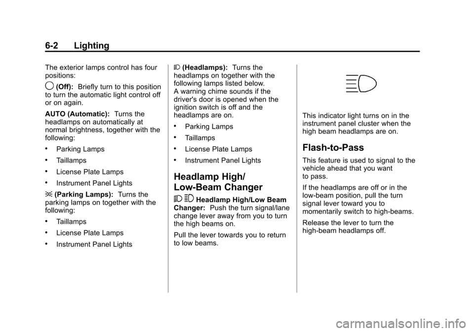
This indicator light turns on in the
instrument panel cluster when the
high beam headlamps are on.
Flash-to-Pass
This feature is used to signal to the
vehicle ahead that you want
to pass.
If the headlamps are off or in the
low‐beam position, pull the turn
signal lever toward you to
momentarily switch to high‐beams.
Release the lever to turn the
high-beam headlamps off.
Page 181 of 448

Lighting 6-3
Daytime Running Lamps
(DRL)/Automatic
Headlamp System
Daytime Running Lamps (DRL) can
make it easier for others to see the
front of your vehicle during the day.
Fully functional daytime running
lamps are required on all vehicles
first sold in Canada.
The DRL system makes the
low-beam headlamps come on at a
reduced brightness when the
following conditions are met:
.The ignition is in the ON/RUN
position.
.The exterior lamps control is
in AUTO.
.The engine is running.
When the DRL are on, the regular
headlamps, taillamps, sidemarker,
and other lamps will not be on. The
instrument panel and cluster will
also not be lit. The headlamps automatically
change from DRL to the regular
headlamps depending on the
darkness of the surroundings. The
other lamps that come on with the
headlamps will also come on.
When it is bright enough outside,
the headlamps will go off and the
DRL will come on.
Do not cover the light sensor on top
of the instrument panel because it
works with the DRL.
Delayed Headlamps
Delayed headlamps provide a
period of exterior lighting as you
leave the area around the vehicle.
This feature is activated when the
headlamps are on due to the
automatic headlamps control
feature, and when the ignition is
turned off. The headlamps remain
on until the exterior lamps control is
moved to the parking lamps position
or until the pre-selected delayed
headlamp lighting period has ended.If the ignition is turned off with the
exterior lamp control in the parking
lamps or headlamps position, the
delayed headlamps cycle will not
occur.
To disable the delayed headlamps
feature or change the time of delay,
see
Vehicle Personalization (With
DIC Buttons) on page 5‑40.
Hazard Warning Flashers
|
Hazard Warning Flasher:
Press this button located on the
instrument panel below the audio
system, to make the front and rear
turn signal lamps flash on and off.
This warns others that you are
having trouble. Press again to turn
the flashers off.
The turn signals do not work while
the hazard warning flashers are on.
Page 184 of 448
6-6 Lighting
When the ignition is on, illuminated
entry is inactive, which means the
courtesy lamps will not come on
unless a door is opened.
Delayed Entry Lighting
Delayed entry lighting illuminates
the interior for a period of time after
all the doors have been closed.
The ignition must be off for delayed
entry lighting to work. Immediately
after all the doors have been closed,
the delayed entry lighting feature
continues to work until one of the
following occurs:
.The ignition is in ON/RUN.
.The doors are locked.
.An illumination period of about
25 seconds has elapsed.
If during the illumination period a
door is opened, the timed
illumination period is canceled and
the interior lamps remain on.
Delayed Exit Lighting
Delayed exit lighting illuminates the
interior for a period of time after the
key is removed from the ignition.
The ignition must be off for delayed
exit lighting to work. When the key
is removed, interior illumination
activates and remains on until one
of the following occurs:
.The ignition is in ON/RUN.
.The power door locks are
activated.
.An illumination period of
20 seconds has elapsed.
If during the illumination period a
door is opened, the timed
illumination period will be canceled
and the interior lamps will remain on
because a door is open.
Parade Dimming
This feature automatically prohibits
the dimming of the instrument panel
displays in daylight while the
headlamps are on so that the
displays are still able to be seen.
Battery Load
Management
The vehicle has Electric Power
Management (EPM) that estimates
the battery's temperature and state
of charge. It then adjusts the voltage
for best performance and extended
life of the battery.
When the battery's state of charge
is low, the voltage is raised slightly
to quickly bring the charge back up.
When the state of charge is high,
the voltage is lowered slightly to
prevent overcharging. If the vehicle
has a voltmeter gauge or a voltage
display on the Driver Information
Center (DIC), you may see the
Page 185 of 448
Lighting 6-7
voltage move up or down. This is
normal. If there is a problem, an
alert will be displayed.
The battery can be discharged at
idle if the electrical loads are very
high. This is true for all vehicles.
This is because the generator
(alternator) may not be spinning fast
enough at idle to produce all the
power that is needed for very high
electrical loads.
A high electrical load occurs when
several of the following are on, such
as: headlamps, high beams, fog
lamps, rear window defogger,
climate control fan at high speed,
heated seats, engine cooling fans,
trailer loads, and loads plugged into
accessory power outlets.
EPM works to prevent excessive
discharge of the battery. It does this
by balancing the generator's output
and the vehicle's electrical needs.
It can increase engine idle speed to
generate more power, wheneverneeded. It can temporarily reduce
the power demands of some
accessories.
Normally, these actions occur in
steps or levels, without being
noticeable. In rare cases at the
highest levels of corrective action,
this action may be noticeable to the
driver. If so, a Driver Information
Center (DIC) message might be
displayed, such as BATTERY
SAVER ACTIVE, BATTERY
VOLTAGE LOW, or LOW BATTERY.
If one of these messages displays, it
is recommended that the driver
reduce the electrical loads as much
as possible. See
Driver Information
Center (DIC) (With DIC Buttons)
on
page 5‑22or Driver Information
Center (DIC) (Without DIC Buttons)
on page 5‑28.
Battery Power Protection
This feature helps prevent the
battery from being drained, if the
interior courtesy lamps, reading/map
lamps, visor vanity lamps or trunk
lamp are accidentally left on. If any
of these lamps are left on, they
automatically turn off after
10 minutes, if the ignition is off. The
lamps will not come back on again
until one of the following occurs:
.The ignition is turned on.
.The exterior lamps control is
turned off, then on again.
The headlamps will timeout after
10 minutes, if they are manually
turned on while the ignition is on
or off.
Page 263 of 448
Driving and Operating 9-11
If it takes some time for help to
arrive, now and then when you run
the engine, push the accelerator
pedal slightly so the engine runs
faster than the idle speed. This
keeps the battery charged to restart
the vehicle and to signal for help
with the headlamps. Do this as little
as possible to save fuel.
If the Vehicle is Stuck
Slowly and cautiously spin the
wheels to free the vehicle when
stuck in sand, mud, ice, or snow.
If the vehicle has a traction system,
it can often help to free a stuck
vehicle. Refer to the vehicle's
traction system in the Index. If stuck
too severely for the traction system
to free the vehicle, turn the traction
system off and use the rocking
method.
{WARNING
If the vehicle's tires spin at high
speed, they can explode, and you
or others could be injured. The
vehicle can overheat, causing an
engine compartment fire or other
damage. Spin the wheels as little
as possible and avoid going
above 55 km/h (35 mph) as
shown on the speedometer.
For information about using tire
chains on the vehicle, see Tire
Chains on page 10‑55.
Rocking the Vehicle to Get
it Out
Turn the steering wheel left and
right to clear the area around the
front wheels. Turn off any traction or
stability system. Shift back and forth
between R (Reverse) and a forward
gear, spinning the wheels as little as
possible. To prevent transmission
wear, wait until the wheels stop
spinning before shifting gears.
Release the accelerator pedal while
shifting, and press lightly on the
accelerator pedal when the
transmission is in gear. Slowly
spinning the wheels in the forward
and reverse directions causes a
rocking motion that could free the
vehicle. If that does not get the
vehicle out after a few tries, it might
need to be towed out. If the vehicle
does need to be towed out, see
Towing the Vehicle on page 10‑82.
Page 307 of 448
Driving and Operating 9-55
*The fuse for this circuit is installed
in the underhood electrical center,
but the wires are not connected.
They should be connected by your
dealer or a qualified service center.
If the back-up lamp circuit is not
functional, contact your dealer.
If a remote (non-vehicle) battery is
being charged, press the Tow/Haul
mode switch located on the center
console near the climate controls.
This will boost the vehicle system
voltage and properly charge the
battery. If the trailer is too light for
Tow/Haul mode, turn on the
headlamps (Non‐HID only) as a
second way to boost the vehicle
system and charge the battery.Electric Trailer Brake Control
Wiring Provisions
These wiring provisions for an
electric trailer brake controller are
included with the vehicle as part of
the trailer wiring package. The
instrument panel contains blunt cut
wires behind the steering column for
the electric trailer brake controller.
The harness contains the following
wires:
.Red/Black: Power Supply
.White: Brake Switch Signal
.Gray: Illumination
.Dark Blue: Trailer Brake Signal
.Black: Ground
The electric trailer brake controller
should be installed by your dealer or
a qualified service center.
Conversions and
Add-Ons
Add-On Electrical
Equipment
Notice: Do not add anything
electrical to the vehicle unless
you check with your dealer first.
Some electrical equipment can
damage the vehicle and the
damage would not be covered by
the vehicle's warranty. Some
add-on electrical equipment can
keep other components from
working as they should.
Add-on equipment can drain the
vehicle battery, even if the vehicle is
not operating.
The vehicle has an airbag system.
Before attempting to add anything
electrical to the vehicle, see
Servicing the Airbag-Equipped
Vehicle
on page 3‑43and Adding
Equipment to the Airbag-Equipped
Vehicle on page 3‑44.
Page 309 of 448
Vehicle Care 10-1
Vehicle Care
General Information
General Information . . . . . . . . . . 10-2
California Proposition65 Warning . . . . . . . . . . . . . . . . . 10-3
California Perchlorate Materials Requirements . . . . 10-3
Accessories and Modifications . . . . . . . . . . . . . . . 10-3
Vehicle Checks
Doing Your OwnService Work . . . . . . . . . . . . . . . 10-4
Hood . . . . . . . . . . . . . . . . . . . . . . . . 10-5
Engine Compartment Overview . . . . . . . . . . . . . . . . . . . 10-6
Engine Cover . . . . . . . . . . . . . . . . 10-7
Engine Oil . . . . . . . . . . . . . . . . . . . 10-8
Engine Oil Life System . . . . . 10-10
Automatic Transmission Fluid . . . . . . . . . . . . . . . . . . . . . . 10-11
Engine Air Cleaner/Filter . . . . 10-12
Cooling System . . . . . . . . . . . . 10-14
Engine Coolant . . . . . . . . . . . . . 10-14
Engine Overheating . . . . . . . . 10-18 Overheated Engine
Protection
Operating Mode . . . . . . . . . . . 10-20
Power Steering Fluid . . . . . . . 10-20
Washer Fluid . . . . . . . . . . . . . . . 10-21
Brakes . . . . . . . . . . . . . . . . . . . . . 10-22
Brake Fluid . . . . . . . . . . . . . . . . . 10-23
Battery . . . . . . . . . . . . . . . . . . . . . 10-24
Starter Switch Check . . . . . . . 10-25
Automatic Transmission Shift Lock Control System
Check . . . . . . . . . . . . . . . . . . . . . 10-25
Ignition Transmission Lock Check . . . . . . . . . . . . . . . . . . . . . 10-25
Park Brake and P (Park) Mechanism Check . . . . . . . . 10-26
Wiper Blade Replacement . . . . . . . . . . . . . . 10-26
Headlamp Aiming
Headlamp Aiming . . . . . . . . . . 10-27
Bulb Replacement
Bulb Replacement . . . . . . . . . . 10-27
Halogen Bulbs . . . . . . . . . . . . . . 10-27
Taillamps, Turn Signal,Sidemarker, and
Stoplamps . . . . . . . . . . . . . . . . 10-28
Replacement Bulbs . . . . . . . . . 10-29
Electrical System
High Voltage Devices and
Wiring . . . . . . . . . . . . . . . . . . . . . 10-29
Electrical System Overload . . . . . . . . . . . . . . . . . . 10-29
Fuses and Circuit
Breakers . . . . . . . . . . . . . . . . . . 10-30
Engine Compartment Fuse Block . . . . . . . . . . . . . . . . . . . . . 10-30
Instrument Panel Fuse Block . . . . . . . . . . . . . . . . . . . . . 10-33
Wheels and Tires
Tires . . . . . . . . . . . . . . . . . . . . . . . . 10-36
Tire Sidewall Labeling . . . . . . 10-36
Tire Designations . . . . . . . . . . . 10-38
Tire Terminology andDefinitions . . . . . . . . . . . . . . . . 10-39
Tire Pressure . . . . . . . . . . . . . . . 10-42
Tire Pressure Monitor System . . . . . . . . . . . . . . . . . . . 10-43
Tire Pressure Monitor Operation . . . . . . . . . . . . . . . . . 10-44
Tire Inspection . . . . . . . . . . . . . . 10-48
Tire Rotation . . . . . . . . . . . . . . . 10-48
When It Is Time for New Tires . . . . . . . . . . . . . . . . . . . . . . 10-49
Buying New Tires . . . . . . . . . . . 10-50
Page 335 of 448
Vehicle Care 10-27
For the proper size and type see
Maintenance Replacement Partson
page 11‑9.
Backglass Wiper Blade
To replace the backglass wiper
blade:
1. Pull the wiper blade assembly away from the backglass.
The backglass wiper blade will
not lock in a vertical position so
care should be used when
pulling it away from the vehicle.
2. Rotate the wiper blade assembly, hold the wiper arm in
position, and push the blade
away from the wiper arm.
3. Replace the wiper blade.
4. Return the wiper arm and blade assembly to the rest position on
the glass.
Headlamp Aiming
Headlamp aim has been preset at
the factory and should need no
further adjustment.
However, if your vehicle is damaged
in a crash, the headlamp aim may
be affected. Aim adjustment to the
low-beam headlamps may be
necessary if oncoming drivers flash
their high-beam headlamps at you
(for vertical aim).
If the headlamps need to be
re-aimed, it is recommended that
you take the vehicle to your dealer
for service.
Bulb Replacement
For the proper type of replacement
bulbs, see Replacement Bulbson
page 10‑29.
For any bulb changing procedure
not listed in this section, contact
your dealer.
Halogen Bulbs
{WARNING
Halogen bulbs have pressurized
gas inside and can burst if you
drop or scratch the bulb. You or
others could be injured. Be sure
to read and follow the instructions
on the bulb package.
Page 337 of 448
Vehicle Care 10-29
9. Push the taillamp assembly backinto its original location.
When reinstalling the taillamp
assembly, make sure the pin on
the taillamp assembly lines up
and is inserted correctly into the
opening of the vehicle.
10. Reinstall the two nuts that hold the taillamp assembly in place.
11. Reinstall the two taillamp nut covers.
Replacement Bulbs
Exterior Lamp Bulb
Number
Rear
Sidemarker Lamp 194
Rear Turn Signal
and Taillamps 7443
(W21/5W)
For replacement bulbs not listed
here, contact your dealer.
Electrical System
High Voltage Devices and
Wiring
{WARNING
Exposure to high voltage can
cause shock, burns, and even
death. The high voltage systems
in your vehicle can only be
serviced by technicians with
special training.
High voltage devices are
identified by labels. Do not
remove, open, take apart,
or modify these devices. High
voltage cable or wiring has
orange covering. Do not probe,
tamper with, cut, or modify high
voltage cable or wiring.
Electrical System
Overload
The vehicle has fuses and circuit
breakers to protect against an
electrical system overload.
When the current electrical load is
too heavy, the circuit breaker opens
and closes, protecting the circuit
until the current load returns to
normal or the problem is fixed. This
greatly reduces the chance of circuit
overload and fire caused by
electrical problems.
Fuses and circuit breakers protect
the following in the vehicle:
.Headlamp Wiring
.Windshield Wiper Motor
.Power Windows and other
Power Accessories
Page 338 of 448
10-30 Vehicle Care
Headlamp Wiring
An electrical overload may cause
the lamps to go on and off, or in
some cases to remain off. Have the
headlamp wiring checked right away
if the lamps go on and off or
remain off.
Windshield Wipers
If the wiper motor overheats due to
heavy snow or ice, the windshield
wipers will stop until the motor cools
and will then restart.
Although the circuit is protected
from electrical overload, overload
due to heavy snow or ice, may
cause wiper linkage damage.
Always clear ice and heavy snow
from the windshield before using the
windshield wipers.
If the overload is caused by an
electrical problem and not snow or
ice, be sure to get it fixed.
Fuses and Circuit
Breakers
The wiring circuits in your vehicle
are protected from short circuits by
a combination of fuses, circuit
breakers and fusible thermal links.
This greatly reduces the chance of
fires caused by electrical problems.
Look at the silver-colored band
inside the fuse. If the band is broken
or melted, replace the fuse. Be sure
you replace a bad fuse with a new
one of the identical size and rating.
Fuses of the same amperage can
be temporarily borrowed from
another fuse location, if a fuse goes
out. Replace the fuse as soon as
you can.
Engine Compartment
Fuse Block
The underhood fuse block is located
in the engine compartment, on the
passenger side of the vehicle.
Lift the cover for access to the fuse/
relay block.
Notice:Spilling liquid on any
electrical components on the
vehicle may damage it. Always
keep the covers on any electrical
component.
To remove fuses, hold the end of
the fuse between your thumb and
index finger and pull straight out.