bulb CHEVROLET VEGA 1976 1.G Owners Manual
[x] Cancel search | Manufacturer: CHEVROLET, Model Year: 1976, Model line: VEGA, Model: CHEVROLET VEGA 1976 1.GPages: 87, PDF Size: 32.36 MB
Page 6 of 87

Downloaded from www.Manualslib.com manuals search engine BEFORE DRIVING YOUR VEGA
DRIVER CHECKLIST
Before Entering Car
1. See that windows , mirrors and
lights are clean.
2. Visually note inflation condition
of tires.
3. Check that area to rear
is clear
if about
to back up.
Before Driving Off
1. Lock all doors.
2. Position seat.
3. Adjust inside and outside
mirrors.
4. Fasten belt restraints.
5. Check that warning bulbs light
when key
is turned to start posi
tion.
6. Release parking brake (and see
that brake warning light turns
off).
7. Be sure you understand your
car and how to operate it safely.
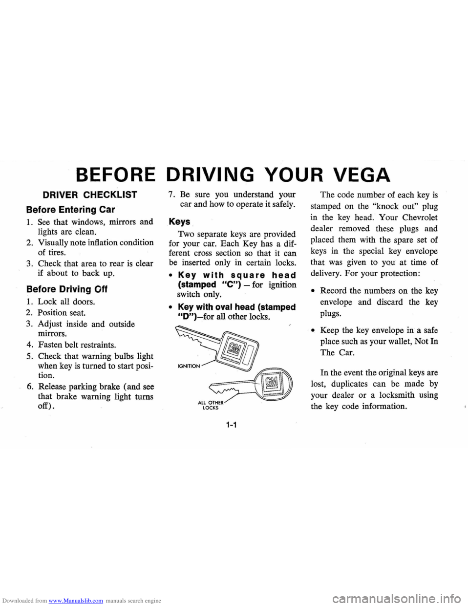
Keys
Two separate keys are provided
for your car. Each Key has a dif
ferent cross section so that it can
be inserted only in certain locks.
• Key with square head
(stamped Ole") -for ignition
switch only.
• Key with oval head (stamped
"D")~for all other locks.
LOCKS
1-1
The code number of each key is
stamped on the "knock out" plug
in the key head. Your Chevrolet
dealer removed these plugs and
placed them with the spare set of
keys in the special key envelope
that was given to you at time of
delivery.
For your protection:
• Record the numbers on the key
envelope and discard the key
plugs.
• Keep the key envelope in a safe
place such
as your wallet, Not In
The Car.
In the event the original keys are
lost, duplicates can be made by
your dealer or a locksmith using
the key code information.
Page 25 of 87

Downloaded from www.Manualslib.com manuals search engine cluster flashes to indicate proper
operation of the front and rear turn
signal lamps.
If the indicator lamp
remains on and does not flash,
check for a defective lamp bulb.
If
the indicator fails to light when the
lever
is moved, check the fuse and
indicator bulb.
NOTE: For operation of hazard
flasher, see page 3-1, in
Section "In
Case of Emergency."
Horn
The horn on your car is actuated
by firmly pressing on the pad in the
center of the steering wheel.
As a good motorist,
~se of the
horn should be kept at a minimum.
However, acquaint yourself
as soon
as possible with this function of
your car, should it ever become
necessary to give a warning to a
pedestrian
or another motorist.
Power Steering
If the steering system power as
sist fails due to some malfunction,
or because the engine has stalled,
the vehicle can still be steered.
However, much greater effort
is re
quired, particularly in sharp turns.
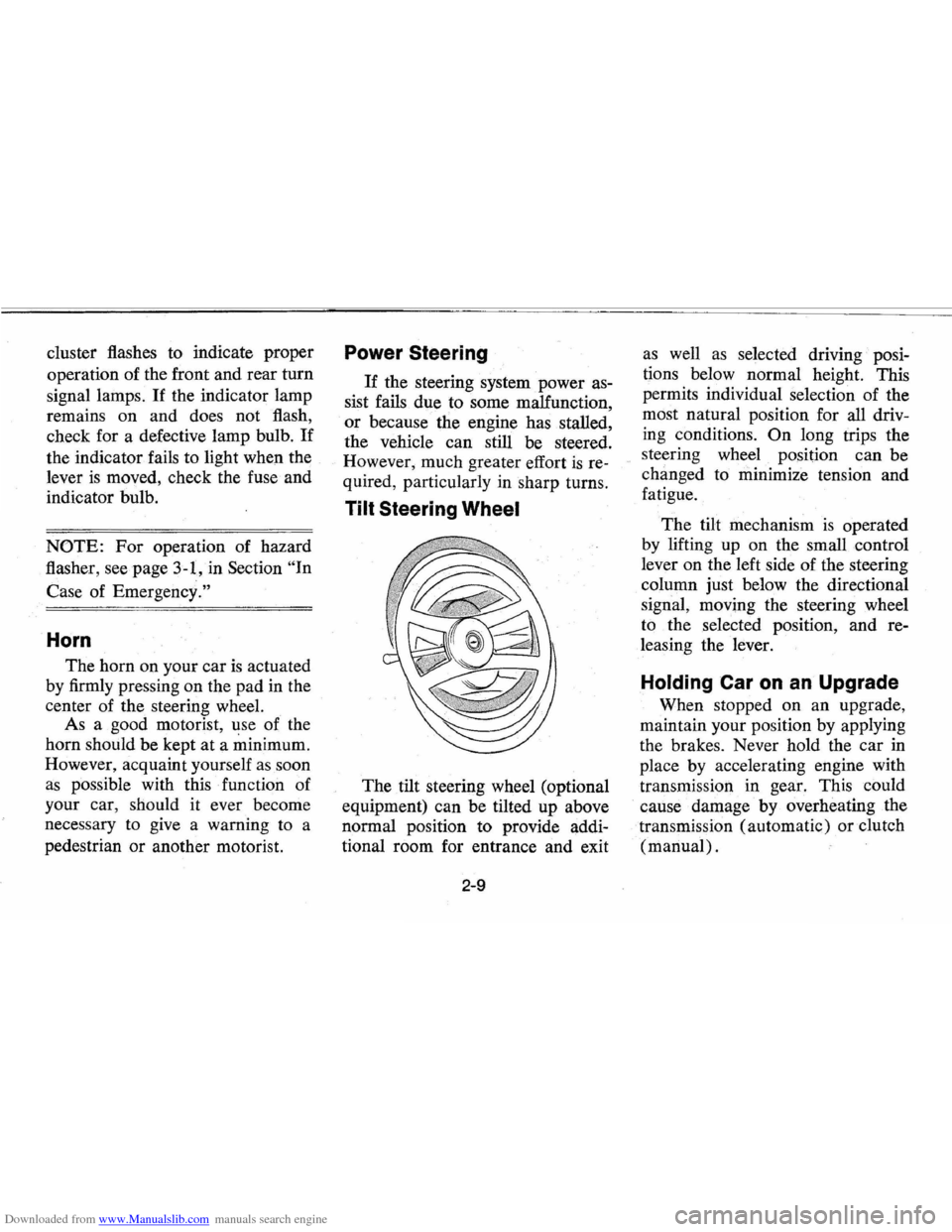
Tilt Steering Wheel
The tilt steering wheel (optional
equipment) can be tilted up above
normal position to provide addi
tional room for entrance and exit
2-9
as well as selected driving· posi
tions below normal height. This
permits individual selection of the
most natural position for
all driv
ing conditions.
On long trips the
steering wheel position can be
changed to minimize tension and
fatigue.
The tilt mechanism
is operated
by lifting up on the small control
lever on the left side of the steering
column just below the directional
signal, moving the steering wheel
to the selected position, and re
leasing the lever.
Holding Car on an Upgrade
When stopped on an upgrade,
maintain your position by applying
the brakes. Never hold the car
in
place by accelerating engine with
transmission in gear. This could
cause damage by overheating
the
. transmission (automatic) or clutch
(manual) .
Page 32 of 87

Downloaded from www.Manualslib.com manuals search engine • The light is also designed to come
on during engine starting to
verify that the bulb
is operating
properly.
• Have system repaired if light does
not come
on during check.
• This warning light is not a substi
tute for the visual check of brake
fluid level required
as part of
normal maintenance.
If the light comes on:
• The parking brake control is not
fully released, or,
• The service brake system is par
tially inoperative.
What to do:
1. Check that parking brake is re
leased.
If it is . . .
2.
Pull off the road and stop, care
fully-remembering that:
• Stopping distances may be
greater.
• Greater pedal effort may be re
quired.
• Pedal travel may be greater. 3.
Try out brake operation by start
ing and s,topping on road shoul
der-then:
• If you judge such operation to
be safe, proceed cautiously at
a safe speed to nearest dealer
for repair.
• Or have car towed to dealer for
repair.
Continued operation of the car in this
condition
is dangerous.
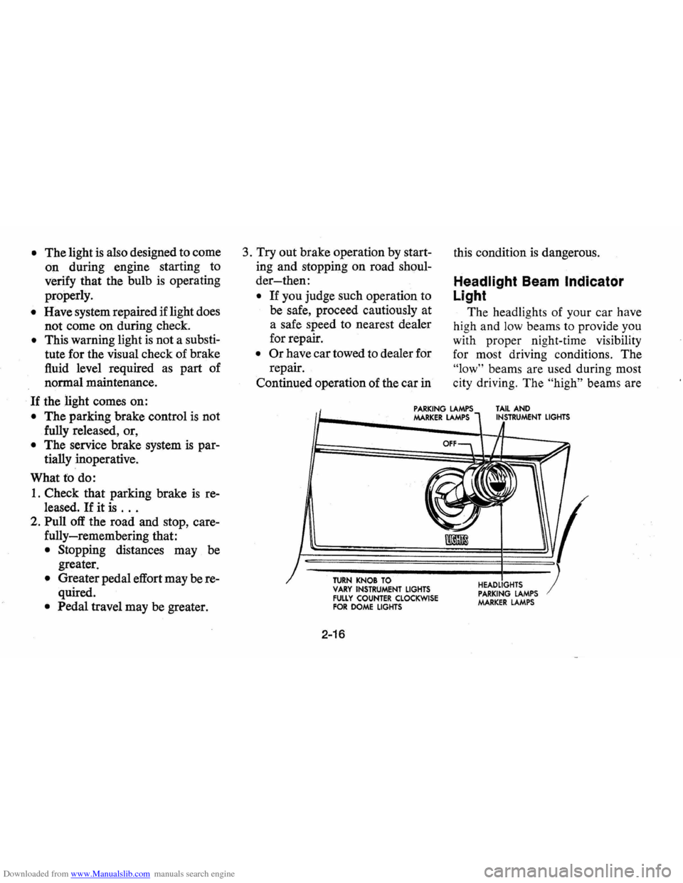
Headlight Beam Indicator
Light
The headlights of your car have
high and
low beams to provide you
with proper night-time visibility
for most driving conditions. The
"low" beams are used during most
city driving. The
"high" beams are
PARKING LAMPS MARKER LAMPS TAIL AND INSTRUMENT LIGHTS
TURN KNOB TO VARY INSTRUMENT LIGHTS FULLY COUNTER CLOCKWISE FOR DOME LIGHTS
2-16
HEADLIGHTS PARKING LAMPS MARKER LAMPS
Page 85 of 87

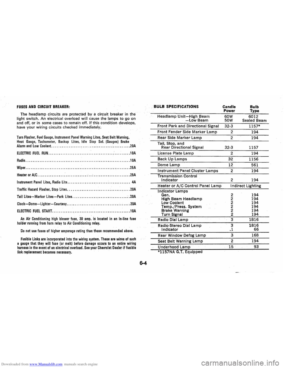
Downloaded from www.Manualslib.com manuals search engine FUSES AND CIRCUIT BREAKER:
The headlamp circuits are protected by a circuit breaker in the
light switch . An -electrical overload will cause the lamps to go on
and off. or in some cases to remain off. If this condition develops,
have your wiring circuits checked immediately.
Turn Flasher, Fuel Gauge,lnstrument Panel Warning Lites, Seat Belt Warning, Heat Gauge. Tachometer. Backup lites, Idle Stop Sol. (Gauges) Brake Alarm and Low Coolant. ............................................ 20A
ELECTRIC FUEL RUN ..................•........................•... 1 OA
Radio ............................................................ 10A
Wiper. ........................................................... 25A
Heater or A/C ............... .-............ ; .. ; ..................... 25A
Instrument Panel Lites, Radio Lite ...........•....... ................. 4A
Traffic Hazard Flasher, Stop Lites ...........•.•................•••... 20A
Tail Lites-Marker lites-Park Lites ...........•.............. .•..... 20A
Clock-Dome-Lighter-Courtesy ..... .......................... ; ..... 20A
ElECTRIC FUEL START ...•................•.•••.•......•.•.••...... 10A
An Air Conditioning high blower fuse, 30 amp. is located in an In-line fuse holder running from horn relay to Air Conditioning relay.
Do not use fuses of higher amperage rating than those recommended above.
Fusible Links are incorporated into the wiring system, These are wires of such a gauge that they will fuse (or melt) before damage occurs to an entire wiring harness in the event of an electrical overload. See your Chevrolet Dealer if fusible link replacement becomes necessary.
BULB SPECIFICATIONS
Headlamp Unit-High Beam -Low Beam
Front Park and Directional
Signal
Front Fender Side Marker Lamp
_ Rear Side Marker Lamp
Tail,
Stop, and
Rear Directional Signal
License Plate Lamp
Back
Up Lamps
Dome Lamp
Instrument Panel Cluster Lamps
Transmission Control
Indicator
Heater
or A/C Control Panel Lamp
I ndicator Lamps
Gen. High Beam Headlamp
Low Coolant
Temp./Press.
System Brake Warning
Turn Signal
Radio Dial Lamp
Radio-Stereo Dial Lamp
Indicator
Rear Window Defog Lamp
Seat Belt Warning Lamp
Underhood Lamp
*1l57NA G.T. Equipped
Candle
Bulb Power Type
60W 6012 SOW Sealed Beam
32-3
1157*
2 194
2 194
32-3 1157
2
194
32 1156
12 561
2
194
2 194
I ndirect Lighting
2
194 2 194 2 194 2 194 2 194 2 194
3 1816
3 1816 .1 66
3 168
2 194
15 93