instrument panel CHRYSLER 200 2013 1.G User Guide
[x] Cancel search | Manufacturer: CHRYSLER, Model Year: 2013, Model line: 200, Model: CHRYSLER 200 2013 1.GPages: 108, PDF Size: 3.81 MB
Page 7 of 108
A. Turn Signal/Lights Lever (behind steeringwheel) pg. 16
B. Electronic Vehicle Information Center (EVIC) Display (behind steering wheel)
pg. 6
C. Instrument Cluster pg. 6
D. Wiper/Washer Lever (behind steering wheel) pg. 18
E. Audio System (touch-screen-radio shown) pg. 24 F. SWITCH PANEL
• Heated Seat Switches pg. 15
• Electronic Stability Control pg. 69
• Hazard Switch
G. Climate Controls pg. 20
H. Transmission Gear Selector
I. Park Brake Lever
J. Power Outlet/Cigar Lighter pg. 66 K. USB Port
L. Electronic Speed Control pg. 19
M. Electronic Vehicle Information Center
(EVIC) Controls pg. 61
N. Hood Release pg. 84
O. Power Mirrors
P. Power Door Locks
Q. Power Windows
CONTROLS AT A GLANCE
5
Page 12 of 108
SUPPLEMENTAL RESTRAINT SYSTEM (SRS) —
AIR BAGS
• This vehicle has Advanced Front Air Bags for both the driver and front passenger as asupplement to the seat belt restraint systems. The driver's Advanced Front Air Bag is mounted
in the center of the steering wheel. The passenger's Advanced Front Air Bag is mounted in the
instrument panel, above the glove compartment. The words SRS AIR BAG are embossed on
the air bag covers. In addition, the vehicle is equipped with Supplemental Driver’s Side Knee
Air Bag mounted in the instrument panel below the steering column and a Knee Bolster below
the glove compartment.
• Advanced Front Air Bags are designed to provide additional protection by supplementing the seat belts in certain frontal collisions depending on several factors, including the severity and
type of collision. Advanced Front Air Bags are not expected to reduce the risk of injury in rear,
side, or rollover collisions.
• This vehicle is equipped with Supplemental Side Air Bag Inflatable Curtains to protect the driver, front and rear passengers sitting next to a window.
• This vehicle is equipped with Supplemental Seat-Mounted Side Air Bags to provide enhanced protection to help protect an occupant during a side impact.
• This vehicle is equipped with Supplemental Driver’s Side Knee Air Bag mounted in the instrument panel below the steering column and a Knee Bolster mounted below the glove
compartment.
• If the Air Bag Warning Light
is not on during starting, stays on, or turns on while driving,
have the vehicle serviced by an authorized service center immediately.
• Refer to the Owner's Manual on the DVD for further details regarding the Supplemental Restraint System (SRS).
WARNING!
• Relying on the air bags alone could lead to more severe injuries in a collision. The air bags work with your seat belt to restrain you properly. In some collisions, the air bags won't
deploy at all. Always wear your seat belts even though you have air bags.
• Being too close to the steering wheel or instrument panel during Advanced Front Air Bag deployment could cause serious injury, including death. Air bags need room to inflate. Sit
back, comfortably extending your arms to reach the steering wheel or instrument panel.
• Supplemental Side Air Bag Inflatable Curtains and Supplemental Seat-Mounted Side Air Bags need room to inflate. Do not lean against the door or window. Sit upright in the
center of the seat.
• Being too close to the Supplemental Side Air Bag Inflatable Curtain and/or Seat- Mounted Side Air Bag during deployment could cause you to be severely injured or killed.
• Do not drive your vehicle after the air bags have deployed. If you are involved in another
collision, the air bags will not be in place to protect you.
• After any collision, the vehicle should be taken to an authorized dealer immediately.
GETTING STARTED
10
Page 19 of 108
Headlights/Parking Lights/Automatic Headlights
• Rotate the end of the lever to the first detent for parking lights, the second detent for
headlights
, and the third detent for AUTO.
• When set to AUTO, the system automatically turns the headlights on or off based on ambient light levels.
Instrument Panel Dimmer
• Rotate the center portion of the lever to the extreme bottom position to fully dim theinstrument panel lights and prevent the interior lights from illuminating when a door is opened.
• Rotate the center portion of the lever up to increase the brightness of the instrument panel lights when the parking lights or headlights are on.
• Rotate the center portion of the lever upward to the next detent position to brighten the odometer and radio controls when the parking lights or headlights are on.
• Rotate the center portion of the lever upward to the last detent to turn on the interior lighting.
Flash To Pass
• Pull the lever toward you to activate the high beams. The high beams will remain on until the lever is released.
High Beam Operation
• Push the lever forward to activate the high beams.
NOTE:
For safe driving, turn off the high beams when oncoming traffic is present to prevent headlight
glare and as a courtesy to other motorists.
Front Fog Lights
• Turn on the parking lights or low beam headlights and pull out the end of the lever.
Turn Signals/Lane Change Assist
• Tap the lever up or down once and the turn signal (right or left) will flash three times andautomatically turn off.
OPERATING YOUR VEHICLE
17
Page 56 of 108
STEERING WHEEL AUDIO CONTROLS
•The steering wheel audio controls are located
on the rear surface of the steering wheel.
Right Switch
• Press the switch up or down to increase or decrease the volume.
• Press the button in the center to change modes AM/FM/CD/SAT.
Left Switch
• Press the switch up or down to search for thenext listenable station or select the next or
previous CD track.
• Press the button in the center to select the next preset station (radio) or to change CDs if equipped with a CD Changer.
SETTING THE ANALOG CLOCK
To set the analog clock at the top center of the instrument panel, press and hold the button until
the setting is correct.
Setting The Analog Clock
ELECTRONICS
54
Page 68 of 108
POWER OUTLETS
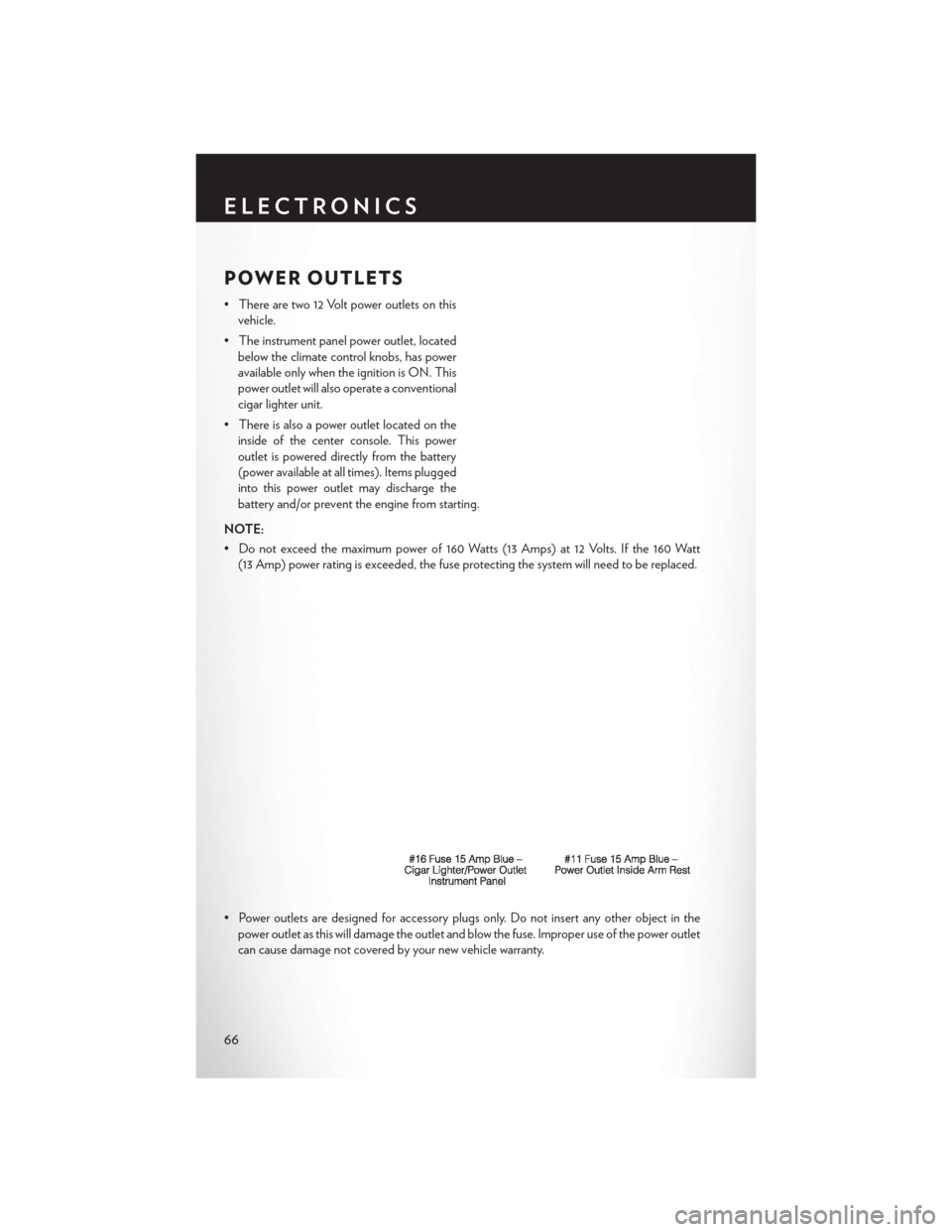
• There are two 12 Volt power outlets on thisvehicle.
• The instrument panel power outlet, located below the climate control knobs, has power
available only when the ignition is ON. This
power outlet will also operate a conventional
cigar lighter unit.
• There is also a power outlet located on the inside of the center console. This power
outlet is powered directly from the battery
(power available at all times). Items plugged
into this power outlet may discharge the
battery and/or prevent the engine from starting.
NOTE:
• Do not exceed the maximum power of 160 Watts (13 Amps) at 12 Volts. If the 160 Watt (13 Amp) power rating is exceeded, the fuse protecting the system will need to be replaced.
• Power outlets are designed for accessory plugs only. Do not insert any other object in the power outlet as this will damage the outlet and blow the fuse. Improper use of the power outlet
can cause damage not covered by your new vehicle warranty.
ELECTRONICS
66
Page 86 of 108
OPENING THE HOOD
• Pull the release lever located below theinstrument panel and in front of the driver’s
door.
• Raise the hood and locate the safety latch, in the middle of the hood opening.
• Move the safety latch while lifting the hood at the same time.
• Insert the support rod into the slot on the hood.
• To close the hood, remove the support rod and place it in the retaining clip, then lower
the hood slowly.
WARNING!
Be sure the hood is fully latched before driving your vehicle. If the hood is not fully latched, it
could open when the vehicle is in motion and block your vision. Failure to follow this warning
could result in serious injury or death.
MAINTAINING YOUR VEHICLE
84
Page 91 of 108
MAINTENANCE SCHEDULE
Your vehicle is equipped with an automatic oil change indicator system. The oil change indicator
system will remind you that it is time to take your vehicle in for scheduled maintenance.
Based on engine operation conditions, the oil change indicator message will illuminate. This
means that service is required for your vehicle. Operating conditions such as frequent short-trips,
trailer tow, extremely hot or cold ambient temperatures, and E85 fuel usage will influence when
the “Oil Change Required” message is displayed. Severe Operating Conditions can cause the
change oil message to illuminate as early as 3,500 miles (5,600 km) since last reset. Have your
vehicle serviced as soon as possible, within the next 500 miles (805 km).
Your authorized dealer will reset the oil change indicator message after completing the scheduled
oil change. If a scheduled oil change is performed by someone other than your authorized dealer,
the message can be reset by referring to the steps described under “Electronic Vehicle Informa-
tion Center (EVIC)/Oil Change Required” in “Understanding Your Instrument Panel” for further
information.
NOTE:
Under no circumstances should oil change intervals exceed 10,000 miles (16,000 km) or twelve
months, whichever comes first.
Once A Month Or Before A Long Trip:
• Check engine oil level
• Check windshield washer fluid level
• Check the tire inflation pressures and look for unusual wear or damage
• Check the fluid levels of the coolant reservoir, brake master cylinder, power steering andtransmission as needed
• Check function of all interior and exterior lights
Required Maintenance Intervals.
Refer to the maintenance schedules on the following page for the required maintenance intervals.
At Every Oil Change Interval As Indicated By Oil Change Indicator System:
• Change oil and filter.
• Rotate the tires. Rotate at the first sign of irregular wear, even if it occurs before the oil
indicator system turns on.
• Inspect battery and clean and tighten terminals as required.
• Inspect automatic transmission fluid if equipped with dipstick.
• Inspect brake pads, shoes, rotors, drums, hoses and park brake.
• Inspect engine cooling system protection and hoses.
• Inspect exhaust system.
• Inspect engine air cleaner if using in dusty or off-road conditions.
MAINTAINING YOUR VEHICLE
89
Page 95 of 108
FUSES
Integrated Power Module
• The Integrated Power Module (fuses) is located in the engine compartment near the aircleaner assembly. This center contains cartridge fuses and mini fuses. A label that identifies
each component may be printed on the inside of the cover.
Cavity Cartridge Fuse Mini Fuse Description
1 40 Amp Green — Power Top Module – If Equipped
2 — 20 Amp Yellow Brake Vacuum Pump
3 —10 Amp Red Center High Mounted Stop Light
(CHMSL)/Brake Switch
4 —10 Amp Red Ignition Switch
5 — 20 Amp Yellow Trailer Tow – If Equipped
6 —10 Amp Red Power Mirror Switch/Climate Controls
7 — 30 Amp Green Ignition Off Draw (IOD) Sense 1
8 — 30 Amp Green Ignition Off Draw (IOD) Sense 2
9 40 Amp Green
Battery Feed – Power Seats – If Equipped
10 — 20 Amp YellowInstrument Panel/Power Locks/Interior
Lights
11— 15 Amp Lt Blue Selectable Power Outlet (Inside Center
Arm Rest)
12 — 20 Amp Yellow —
13 — 20 Amp Yellow Ignition/Cigar Lighter
14 —10 Amp Red Instrument Panel
15 40 Amp Green — Radiator Fan Relay
16 — 15 Amp Lt. Blue Sunroof – If Equipped
17 —10 Amp Red Wireless Control Module (WCM)/
Clock/Steering Control Module (SCM)
18 40 Amp Green — Auto Shutdown (ASD) Relay
MAINTAINING YOUR VEHICLE
93