brake light CHRYSLER 200 2014 1.G User Guide
[x] Cancel search | Manufacturer: CHRYSLER, Model Year: 2014, Model line: 200, Model: CHRYSLER 200 2014 1.GPages: 116, PDF Size: 3.15 MB
Page 8 of 116
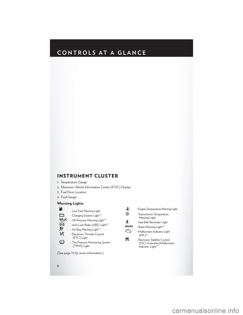
INSTRUMENT CLUSTER
1. Temperature Gauge
2. Electronic Vehicle Information Center (EVIC) Display
3. Fuel Door Location
4. Fuel Gauge
Warning Lights
- Low Fuel Warning Light
- Charging System Light**
- Oil Pressure Warning Light**
- Anti-Lock Brake (ABS) Light**
- Air Bag Warning Light**
- Electronic Throttle Control(ETC) Light
- Tire Pressure Monitoring System(TPMS) Light
- Engine Temperature Warning Light
- Transmission TemperatureWarning Light
- Seat Belt Reminder LightBRAKE- Brake Warning Light**
-Malfunction Indicator Light
(MIL)**
- Electronic Stability Control (ESC) Activation/Malfunction
Indicator Light**
(See page 75 for more information.)
CONTROLS AT A GLANCE
6
Page 10 of 116
KEY FOB
Locking And Unlocking The Doors
• Press and release the LOCK button on theRKE transmitter to lock both doors. The
turn signal lights will flash and the horn will
chirp to acknowledge the signal.
• Press and release the UNLOCK button on the RKE transmitter once to unlock the
driver’s door (EVIC can be setup for driver
door first, otherwise this will unlock all
doors), or press the unlock button twice
within five seconds to unlock all doors.
The turn signal lights will flash to acknowl-
edge the unlock signal. The illuminated
entry system will also turn on.
• All doors can be programmed to unlock on the first press of the UNLOCK button.
Refer to Programmable Features in this
guide.
Opening The Trunk
• Press the Trunk Release button on the trans-
mitter two times within five seconds to open
the trunk.
Panic Alarm
• Press the PANIC button once to turn the panic alarm on.
• Wait approximately three seconds and press the button a second time to turn the panicalarm off.
WARNING!
• When leaving the vehicle, always remove the Key Fob from the ignition and lock your
vehicle.
• Never leave children alone in a vehicle, or with access to an unlocked vehicle. Allowing
children to be in a vehicle unattended is dangerous for a number of reasons. A child or
others could be seriously or fatally injured. Children should be warned not to touch the
parking brake, brake pedal or the shift lever.
• Do not leave the Key Fob in the vehicle, or in a location accessible to children. A child
could operate power windows, other controls, or move the vehicle.
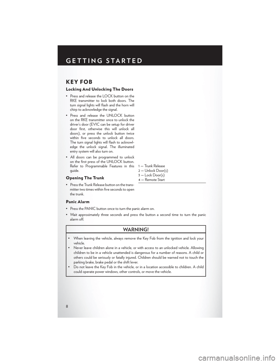
1 — Trunk Release
2 — Unlock Door(s)
3 — Lock Door(s)
4 — Remote Start
GETTING STARTED
8
Page 79 of 116
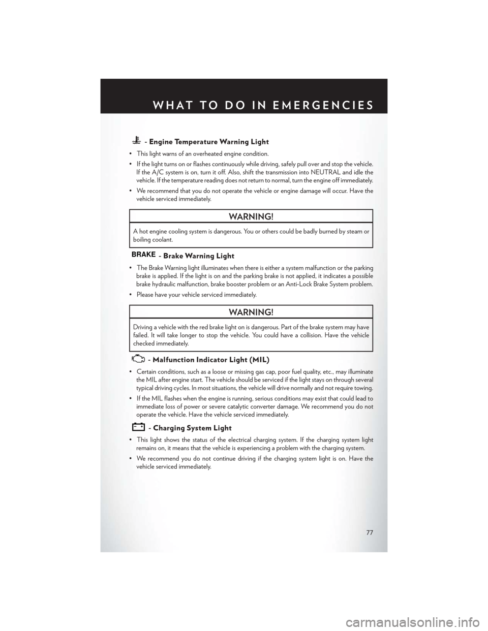
- Engine Temperature Warning Light
• This light warns of an overheated engine condition.
• If the light turns on or flashes continuously while driving, safely pull over and stop the vehicle.If the A/C system is on, turn it off. Also, shift the transmission into NEUTRAL and idle the
vehicle. If the temperature reading does not return to normal, turn the engine off immediately.
• We recommend that you do not operate the vehicle or engine damage will occur. Have the vehicle serviced immediately.
WARNING!
A hot engine cooling system is dangerous. You or others could be badly burned by steam or
boiling coolant.
BRAKE- Brake Warning Light
• The Brake Warning light illuminates when there is either a system malfunction or the parkingbrake is applied. If the light is on and the parking brake is not applied, it indicates a possible
brake hydraulic malfunction, brake booster problem or an Anti-Lock Brake System problem.
• Please have your vehicle serviced immediately.
WARNING!
Driving a vehicle with the red brake light on is dangerous. Part of the brake system may have
failed. It will take longer to stop the vehicle. You could have a collision. Have the vehicle
checked immediately.
- Malfunction Indicator Light (MIL)
• Certain conditions, such as a loose or missing gas cap, poor fuel quality, etc., may illuminate the MIL after engine start. The vehicle should be serviced if the light stays on through several
typical driving cycles. In most situations, the vehicle will drive normally and not require towing.
• If the MIL flashes when the engine is running, serious conditions may exist that could lead to immediate loss of power or severe catalytic converter damage. We recommend you do not
operate the vehicle. Have the vehicle serviced immediately.
- Charging System Light
• This light shows the status of the electrical charging system. If the charging system lightremains on, it means that the vehicle is experiencing a problem with the charging system.
• We recommend you do not continue driving if the charging system light is on. Have the vehicle serviced immediately.
WHAT TO DO IN EMERGENCIES
77
Page 80 of 116
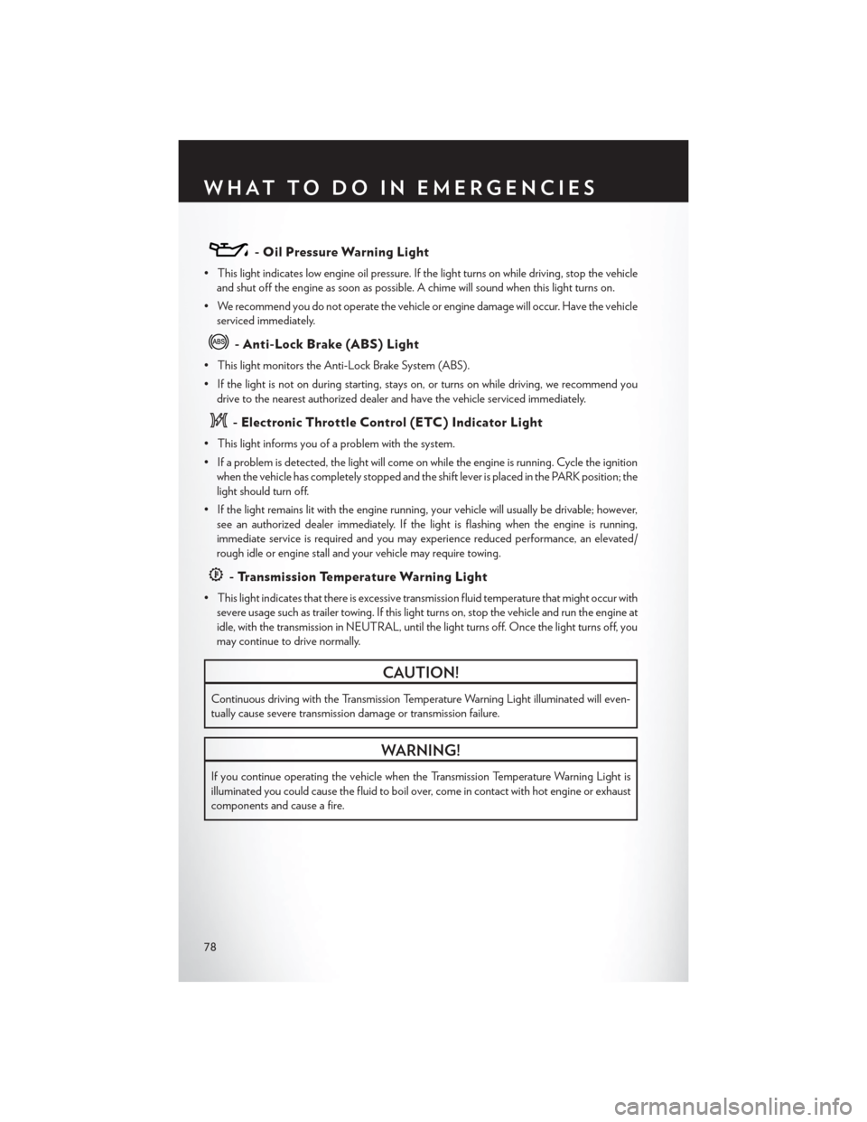
- Oil Pressure Warning Light
• This light indicates low engine oil pressure. If the light turns on while driving, stop the vehicleand shut off the engine as soon as possible. A chime will sound when this light turns on.
• We recommend you do not operate the vehicle or engine damage will occur. Have the vehicle serviced immediately.
- Anti-Lock Brake (ABS) Light
• This light monitors the Anti-Lock Brake System (ABS).
• If the light is not on during starting, stays on, or turns on while driving, we recommend youdrive to the nearest authorized dealer and have the vehicle serviced immediately.
- Electronic Throttle Control (ETC) Indicator Light
• This light informs you of a problem with the system.
• If a problem is detected, the light will come on while the engine is running. Cycle the ignitionwhen the vehicle has completely stopped and the shift lever is placed in the PARK position; the
light should turn off.
• If the light remains lit with the engine running, your vehicle will usually be drivable; however, see an authorized dealer immediately. If the light is flashing when the engine is running,
immediate service is required and you may experience reduced performance, an elevated/
rough idle or engine stall and your vehicle may require towing.
- Transmission Temperature Warning Light
• This light indicates that there is excessive transmission fluid temperature that might occur withsevere usage such as trailer towing. If this light turns on, stop the vehicle and run the engine at
idle, with the transmission in NEUTRAL, until the light turns off. Once the light turns off, you
may continue to drive normally.
CAUTION!
Continuous driving with the Transmission Temperature Warning Light illuminated will even-
tually cause severe transmission damage or transmission failure.
WARNING!
If you continue operating the vehicle when the Transmission Temperature Warning Light is
illuminated you could cause the fluid to boil over, come in contact with hot engine or exhaust
components and cause a fire.
WHAT TO DO IN EMERGENCIES
78
Page 89 of 116
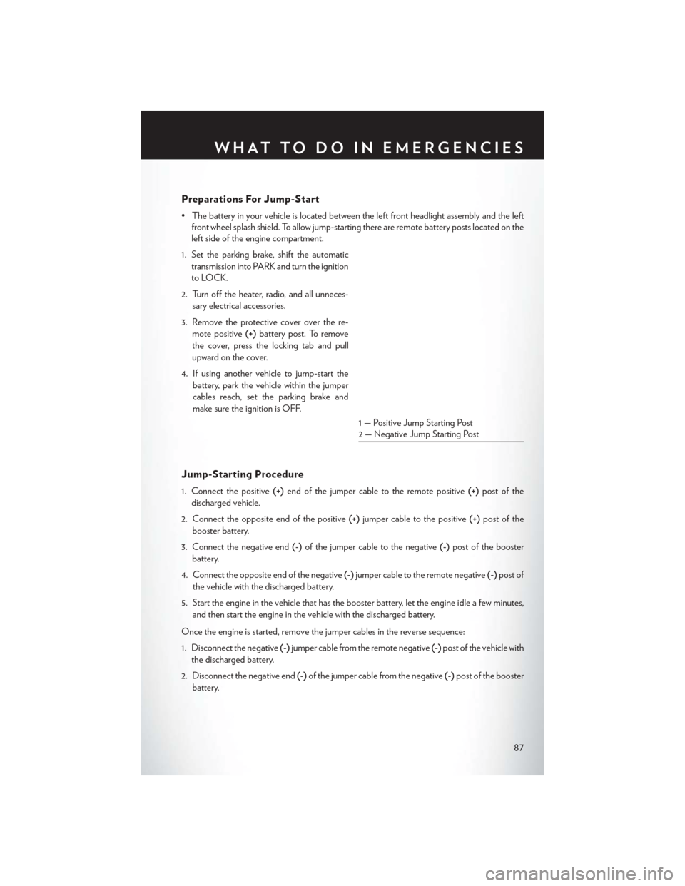
Preparations For Jump-Start
• The battery in your vehicle is located between the left front headlight assembly and the leftfront wheel splash shield. To allow jump-starting there are remote battery posts located on the
left side of the engine compartment.
1. Set the parking brake, shift the automatic transmission into PARK and turn the ignition
to LOCK.
2. Turn off the heater, radio, and all unneces- sary electrical accessories.
3. Remove the protective cover over the re- mote positive (+)battery post. To remove
the cover, press the locking tab and pull
upward on the cover.
4. If using another vehicle to jump-start the battery, park the vehicle within the jumper
cables reach, set the parking brake and
make sure the ignition is OFF.
Jump-Starting Procedure
1. Connect the positive (+)end of the jumper cable to the remote positive (+)post of the
discharged vehicle.
2. Connect the opposite end of the positive (+)jumper cable to the positive (+)post of the
booster battery.
3. Connect the negative end (-)of the jumper cable to the negative (-)post of the booster
battery.
4. Connect the opposite end of the negative (-)jumper cable to the remote negative (-)post of
the vehicle with the discharged battery.
5. Start the engine in the vehicle that has the booster battery, let the engine idle a few minutes, and then start the engine in the vehicle with the discharged battery.
Once the engine is started, remove the jumper cables in the reverse sequence:
1. Disconnect the negative (-)jumper cable from the remote negative (-)post of the vehicle with
the discharged battery.
2. Disconnect the negative end (-)of the jumper cable from the negative (-)post of the booster
battery.
1 — Positive Jump Starting Post
2 — Negative Jump Starting Post
WHAT TO DO IN EMERGENCIES
87
Page 99 of 116
MAINTENANCE SCHEDULE
Your vehicle is equipped with an automatic oil change indicator system. The oil change indicator
system will remind you that it is time to take your vehicle in for scheduled maintenance.
Based on engine operation conditions, the oil change indicator message will illuminate. This
means that service is required for your vehicle. Operating conditions such as frequent short-trips,
trailer tow, extremely hot or cold ambient temperatures, and E85 fuel usage will influence when
the “Oil Change Required” message is displayed. Severe Operating Conditions can cause the
change oil message to illuminate as early as 3,500 miles (5,600 km) since last reset. Have your
vehicle serviced as soon as possible, within the next 500 miles (805 km).
Your authorized dealer will reset the oil change indicator message after completing the scheduled oil
change. If a scheduled oil change is performed by someone other than your authorized dealer, the
message can be reset by referring to the steps described under “Electronic Vehicle Information Center
(EVIC)/Oil Change Required” in “Understanding Your Instrument Panel” for further information.
NOTE:
Under no circumstances should oil change intervals exceed 10,000 miles (16,000 km) or twelve
months, whichever comes first.
Severe Duty All Models
Change Engine Oil at 4000 miles (6,500 km) if the vehicle is operated in a dusty and off road
environment. This type of vehicle use is considered Severe Duty.
Once A Month Or Before A Long Trip:
• Check engine oil level.
• Check windshield washer fluid level.
• Check tire pressure and look for unusual wear or damage. Rotate tires at the first sign ofirregular wear, even if it occurs before the oil indicator system turns on.
• Check the fluid levels of the coolant reservoir, brake master cylinder, power steering and transmission (four-speed only) and fill as needed.
• Check function of all interior and exterior lights.
Required Maintenance Intervals
Refer to the maintenance schedules on the following page for the required maintenance intervals.
At Every Oil Change Interval As Indicated By Oil Change Indicator System:
• Change oil and filter.
• Rotate the tires. Rotate at the first sign of irregular wear, even if it occurs before the oil
indicator system turns on.
• Inspect battery and clean and tighten terminals as required.
• Inspect automatic transmission fluid if equipped with dipstick.
• Inspect brake pads, shoes, rotors, drums, hoses and park brake.
• Inspect engine cooling system protection and hoses.
• Inspect exhaust system.
• Inspect engine air cleaner if using in dusty or off-road conditions.
MAINTAINING YOUR VEHICLE
97
Page 103 of 116
FUSES
Integrated Power Module
• The Integrated Power Module (fuses) is located in the engine compartment near the aircleaner assembly. This center contains cartridge fuses and mini fuses. A label that identifies
each component may be printed on the inside of the cover.
Cavity Cartridge Fuse Mini Fuse Description
1 40 Amp Green — Power Top Module – If Equipped
2 — 20 Amp Yellow Brake Vacuum Pump
3 — 10 Amp Red Center High Mounted Stop Light
(CHMSL)/Brake Switch
4 — 10 Amp Red Ignition Switch
5 — 20 Amp Yellow Trailer Tow – If Equipped
6 — 10 Amp Red Power Mirror Switch/Climate Controls
7 — 30 Amp Green Ignition Off Draw (IOD) Sense 1
8 — 30 Amp Green Ignition Off Draw (IOD) Sense 2
9 40 Amp Green Battery Feed – Power Seats – If
Equipped
10 — 20 Amp Yellow Instrument Panel/Power Locks/Interior
Lights
11 — 15 Amp Lt Blue Selectable Power Outlet (Inside Center
Arm Rest)
12 — 20 Amp Yellow Spare
13 — 20 Amp Yellow Ignition/Cigar Lighter
14 — 10 Amp Red Instrument Panel
15 40 Amp Green — Radiator Fan Relay
16 — 15 Amp Lt. Blue Sunroof – If Equipped
MAINTAINING YOUR VEHICLE
101
Page 106 of 116
WHEEL AND WHEEL TRIM CARE
• All wheels and wheel trim, especially aluminum and chrome plated wheels, should be cleanedregularly with a mild soap and water to prevent corrosion.
• To remove heavy soil and/or excessive brake dust, use MOPAR® Wheel Cleaner or equivalent or select a non-abrasive, non-acidic cleaner.
CAUTION!
Do not use scouring pads, steel wool, a bristle brush, or metal polishes. Do not use oven
cleaner. These products may damage the wheel's protective finish. Avoid automatic car
washes that use acidic solutions or harsh brushes that may damage the wheel's protective
finish. Only MOPAR® Wheel Cleaner or equivalent is recommended.
EXTERIOR BULBS
LIGHT BULBS – Exterior Bulb Number
Bi-Halogen Headlamp HIR2
Front Turn Signal Lamp 3157NAK
Front Park Lamp LED (Serviced at Authorized Dealer)
Front Fog Lamp H11
Center High Mounted Stop (CHMSL) Lamp LED (Serviced at Authorized Dealer)
Rear Tail/Stop/Turn Lamp LED (Serviced at Authorized Dealer)
Backup Lamp 921
License Lamp W5W
Front Side Marker Lamp WY5W
MAINTAINING YOUR VEHICLE
104
Page 110 of 116
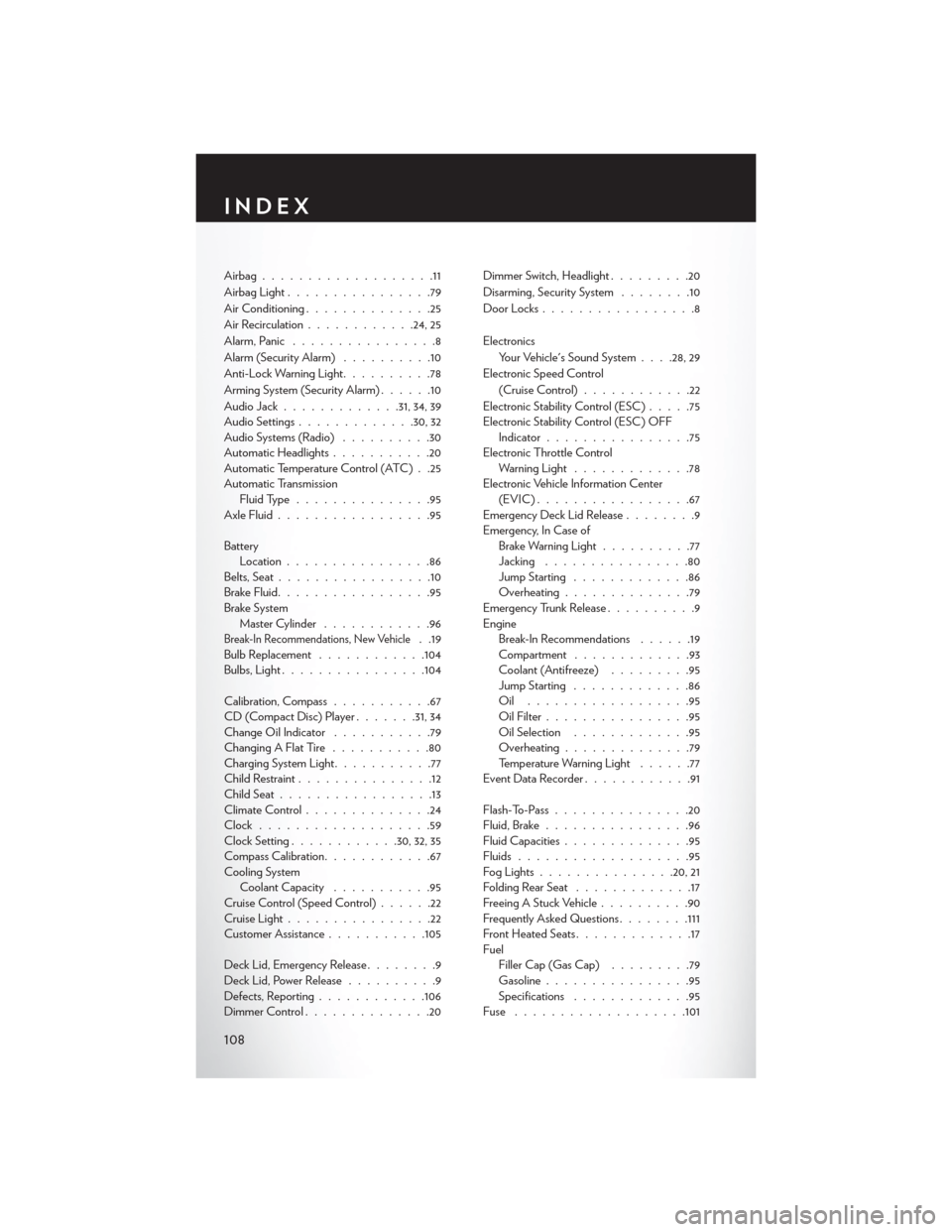
Airbag...................11
AirbagLight................79
Air Conditioning..............25
Air Recirculation ............24, 25
Alarm, Panic ................8
Alarm (Security Alarm) ..........10
Anti-Lock Warning Light ..........78
Arming System (Security Alarm) ......10
Audio Jack ............ .31, 34, 39
Audio Settings ............ .30, 32
Audio Systems (Radio) ..........30
Automatic Headlights ...........20
Automatic Temperature Control (ATC) . .25
Automatic Transmission Fluid Type ...............95
Axle Fluid .................95
Battery Location ................86
Belts, Seat .................10
Brake Fluid .................95
Brake System Master Cylinder ............96
Break-In Recommendations, New Vehicle. .19
Bulb Replacement ............104
Bulbs,Light................104
Calibration, Compass ...........67
CD (Compact Disc) Player .......31, 34
Change Oil Indicator ...........79
Changing A Flat Tire ...........80
Charging System Light ...........77
Child Restraint ...............12
Child Seat .................13
Climate Control ..............24
Clock ...................59
Clock Setting ............30,32,35
Compass Calibration ............67
Cooling System Coolant Capacity ...........95
Cruise Control (Speed Control) ......22
Cruise Light ................22
Customer Assistance ...........105
Deck Lid, Emergency Release ........9
Deck Lid, Power Release ..........9
Defects, Reporting ............106
Dimmer Control ..............20 Dimmer Switch, Headlight
.........20
Disarming, Security System ........10
Door Locks .................8
Electronics Your Vehicle's Sound System . . . .28, 29
Electronic Speed Control (Cruise Control) ............22
Electronic Stability Control (ESC) .....75
Electronic Stability Control (ESC) OFF Indicator ................75
Electronic Throttle Control Warning Light .............78
Electronic Vehicle Information Center (EVIC).................67
Emergency Deck Lid Release ........9
Emergency, In Case of Brake Warning Light ..........77
Jacking ................80
Jump Starting .............86
Overheating ..............79
Emergency Trunk Release ..........9
Engine Break-In Recommendations ......19
Compartment .............93
Coolant (Antifreeze) .........95
Jump Starting .............86
Oil ..................95
Oil Filter ................95
Oil Selection .............95
Overheating ..............79
Temperature Warning Light ......77
EventDataRecorder............91
Flash-To-Pass ...............20
Fluid, Brake ................
96
Fluid Capacities ..............95
Fluids ...................95
FogLights...............20, 21
Folding Rear Seat .............17
Freeing A Stuck Vehicle ..........90
Frequently Asked Questions ........111
Front Heated Seats .............17
Fuel Filler Cap (Gas Cap) .........79
Gasoline ................95
Specifications .............95
Fuse ...................101
INDEX
108