instrument panel CHRYSLER 200 2014 1.G User Guide
[x] Cancel search | Manufacturer: CHRYSLER, Model Year: 2014, Model line: 200, Model: CHRYSLER 200 2014 1.GPages: 116, PDF Size: 3.15 MB
Page 6 of 116
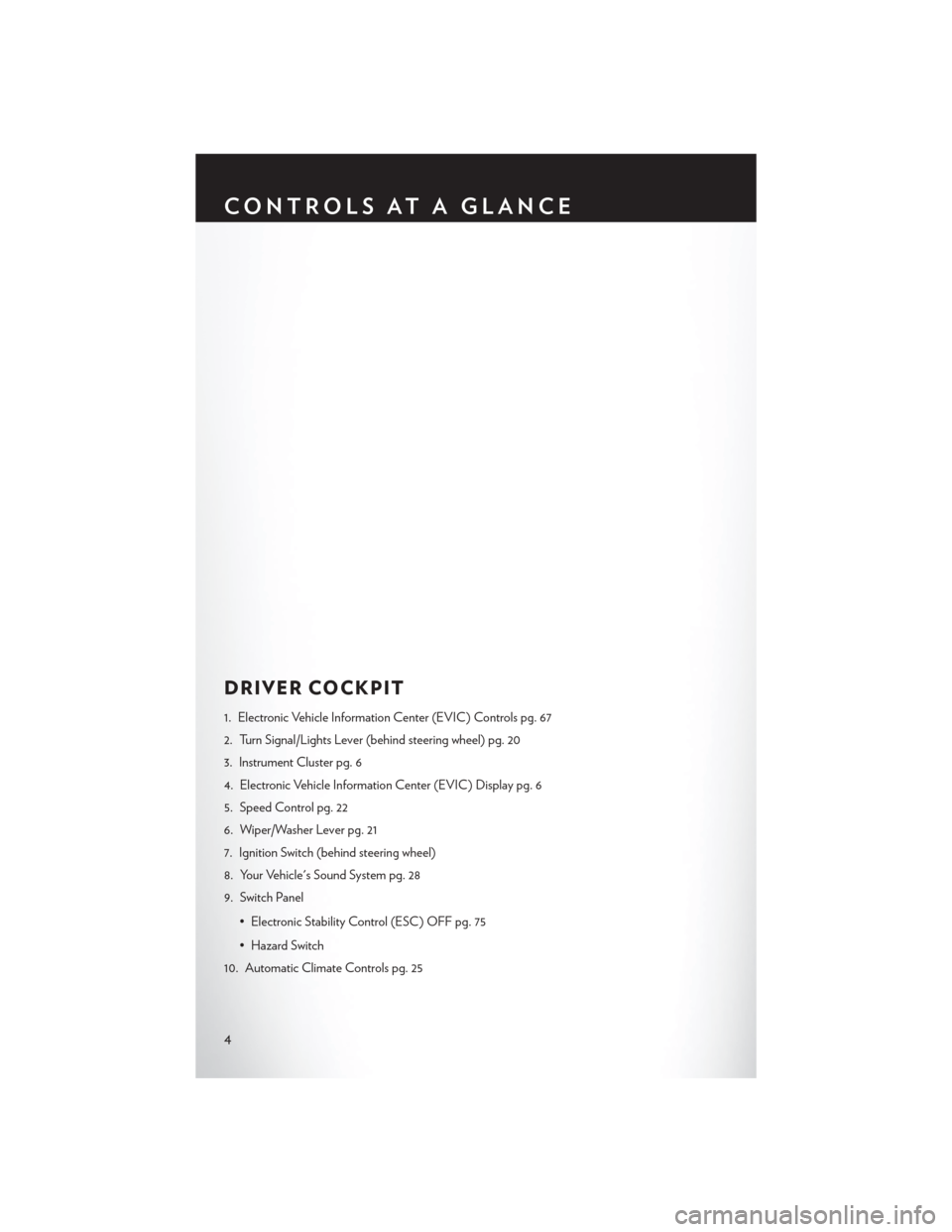
DRIVER COCKPIT
1. Electronic Vehicle Information Center (EVIC) Controls pg. 67
2. Turn Signal/Lights Lever (behind steering wheel) pg. 20
3. Instrument Cluster pg. 6
4. Electronic Vehicle Information Center (EVIC) Display pg. 6
5. Speed Control pg. 22
6. Wiper/Washer Lever pg. 21
7. Ignition Switch (behind steering wheel)
8. Your Vehicle's Sound System pg. 28
9. Switch Panel• Electronic Stability Control (ESC) OFF pg. 75
• Hazard Switch
10. Automatic Climate Controls pg. 25
CONTROLS AT A GLANCE
4
Page 11 of 116
REMOTE START
• Press the REMOTE START buttonx2on the Key Fob twice within five seconds. Pressing
the REMOTE START button a third time shuts the engine off.
• To drive the vehicle, press the UNLOCK button, insert the key in the ignition and turn to the ON/RUN position.
• With remote start, the engine will only run for 15 minutes (timeout) unless the ignition key is placed in the ON/RUN position.
• The vehicle must be started with the key after two consecutive timeouts.
WARNING!
• Do not start or run an engine in a closed garage or confined area. Exhaust gas contains Carbon Monoxide (CO) which is odorless and colorless. Carbon Monoxide is poisonous
and can cause you or others to be severely injured or killed when inhaled.
• Keep Key Fob transmitters away from children. Operation of the Remote Start System, windows, door locks or other controls could cause you and others to be severely injured or
killed.
TRUNK LOCK AND RELEASE
• Use the Remote Keyless Entry (RKE) transmitter to open the trunk from outside the vehicle.From inside the vehicle the trunk lid can be released by pressing the TRUNK RELEASE
button located on the instrument panel to the left of the steering wheel.
NOTE:
The shift lever must be in PARK for this button to operate.
• To unlatch the trunk lid from outside the vehicle, press and release the TRUNK button on the RKE transmitter two times.
• With the ignition switch in the ON/RUN position, the word “dECK” will display in place of the odometer display indicating that the trunk is open. The odometer display will reappear once
the trunk is closed or if the trip button is depressed.
• With the ignition switch in the LOCK position or with the key out, the word “dECK” will display until the trunk is closed.
• On EVIC-equipped vehicles, the words “Trunk Ajar” will display.
Trunk Emergency Release
• As a security measure, a Trunk Internal Emergency Release lever is built into the trunk latching mechanism. In the event of an individual being locked inside the trunk, the trunk can be simply
opened by pulling on the glow-in-the-dark handle attached to the trunk latching mechanism.
WARNING!
Do not allow children to have access to the trunk, either by climbing into the trunk from
outside, or through the inside of the vehicle. Always close the trunk lid when your vehicle is
unattended. Once in the trunk, young children may not be able to escape, even if they entered
through the rear seat. If trapped in the trunk, children can die from suffocation or heat stroke.
GETTING STARTED
9
Page 12 of 116
SECURITY ALARM
To Arm:
• Lock the door using either the power door lock switch (one door must be open) or the LOCKbutton on the Remote Keyless Entry (RKE) transmitter (doors can be open or closed), and
close all doors.
NOTE:
The Vehicle Security Alarm will not arm if you lock the doors with the manual door lock plungers.
• The Vehicle Security Light in the instrument cluster will flash for 16 seconds. This shows that the Vehicle Security Alarm is arming. During this period, if a door is opened, the ignition is
cycled to ON/RUN, or the power door locks are unlocked in any manner, the Vehicle Security
Alarm will automatically disarm.
NOTE:
• During the 16-second arming period, if a door is opened or the ignition is cycled to ON/RUN, the Vehicle Security Alarm will automatically disarm.
• Once armed, the Vehicle Security Alarm disables the unlock switch on the driver door trim panel and passenger door trim panel.
To Disarm The System:
• Press the Key Fob UNLOCK button or cycle the ignition to the ON/START position.
• The Vehicle Security Alarm is designed to protect your vehicle; however, you can createconditions where the Vehicle Security Alarm will give you a false alarm. If one of the previously
described arming sequences has occurred, the Vehicle Security Alarm will arm regardless of
whether you are in the vehicle or not. If you remain in the vehicle and open a door, the alarm
will sound. If this occurs, disarm the Vehicle Security Alarm.
• If the Vehicle Security Alarm is armed and the battery becomes disconnected the Vehicle Security Alarm will remain armed when the battery is reconnected. The exterior lights will
flash, and the horn will sound. If this occurs, disarm the Vehicle Security Alarm.
SEAT BELT
• Be sure everyone in your vehicle is in a seat and using a seat belt properly.
• Position the lap belt across your thighs, below your abdomen. To remove slack in the lapportion, pull up a bit on the shoulder belt. To loosen the lap belt if it is too tight, tilt the latch
plate and pull on the lap belt. A snug belt reduces the risk of sliding under the belt in a collision.
• Position the shoulder belt on your chest so that it is comfortable and not resting on your neck. The retractor will withdraw any slack in the belt.
• A shoulder belt placed behind you will not protect you from injury during a collision. You are more likely to hit your head in a collision if you do not wear your shoulder belt. The lap and
shoulder belt are meant to be used together.
GETTING STARTED
10
Page 14 of 116
WARNING!
• Relying on the air bags alone could lead to more severe injuries in a collision. The air bagswork with your seat belt to restrain you properly. In some collisions, the air bags won't
deploy at all. Always wear your seat belts even though you have air bags.
• Being too close to the steering wheel or instrument panel during Advanced Front Air Bag
deployment could cause serious injury, including death. Air bags need room to inflate.
Sit back, comfortably extending your arms to reach the steering wheel or instrument
panel.
•
Supplemental Side Air Bag Inflatable Curtains and Supplemental Seat-Mounted Side Air
Bags need room to inflate. Do not lean against the door or window. Sit upright in the center
of the seat.
• Being too close to the Supplemental Side Air Bag Inflatable Curtain and/or Seat-
Mounted Side Air Bag during deployment could cause you to be severely injured or killed.
• Do not drive your vehicle after the air bags have deployed. If you are involved in another
collision, the air bags will not be in place to protect you.
• After any collision, the vehicle should be taken to an authorized dealer immediately.
CHILD RESTRAINTS
• Children 12 years or younger should ride properly buckled up in a rear seat, if available. According to crash statistics, children are safer when properly restrained in the rear seats rather
than in the front.
• Every state in the United States and all Canadian provinces require that small children ride in proper restraint systems. This is the law, and you can be prosecuted for ignoring it.
NOTE:
• For additional information, refer to www.seatcheck.org or call 1–866–SEATCHECK (1–866– 732–8243).
• Canadian residents, should refer to Transport Canada’s website for additional information: http://www.tc.gc.ca/eng/roadsafety/safedrivers-childsafety-index-53.htm
LATCH — Lower Anchors And Tethers For CHildren
• Your vehicle is equipped with the child restraint anchorage system called LATCH, whichstands for Lower Anchors and Tethers for CHildren.
• The rear outboard seating positions have lower anchors and top tether anchors. The rear center seating position has a top tether anchor only.
• You may use the LATCH anchorage system until the combined weight of the child and the child restraint is 65 lbs (29.5 kg). Use the seat belt and tether anchor instead of the LATCH
system once the combined weight is more than 65 lbs (29.5 kg).
GETTING STARTED
12
Page 22 of 116
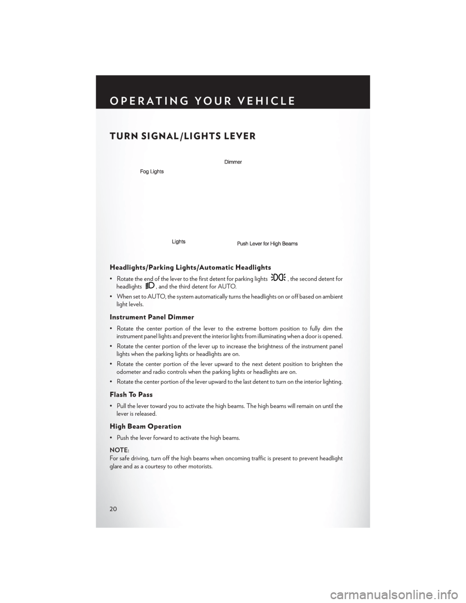
TURN SIGNAL/LIGHTS LEVER
Headlights/Parking Lights/Automatic Headlights
• Rotate the end of the lever to the first detent for parking lights, the second detent for
headlights
, and the third detent for AUTO.
• When set to AUTO, the system automatically turns the headlights on or off based on ambient light levels.
Instrument Panel Dimmer
• Rotate the center portion of the lever to the extreme bottom position to fully dim theinstrument panel lights and prevent the interior lights from illuminating when a door is opened.
• Rotate the center portion of the lever up to increase the brightness of the instrument panel lights when the parking lights or headlights are on.
• Rotate the center portion of the lever upward to the next detent position to brighten the odometer and radio controls when the parking lights or headlights are on.
• Rotate the center portion of the lever upward to the last detent to turn on the interior lighting.
Flash To Pass
• Pull the lever toward you to activate the high beams. The high beams will remain on until the lever is released.
High Beam Operation
• Push the lever forward to activate the high beams.
NOTE:
For safe driving, turn off the high beams when oncoming traffic is present to prevent headlight
glare and as a courtesy to other motorists.
OPERATING YOUR VEHICLE
20
Page 61 of 116
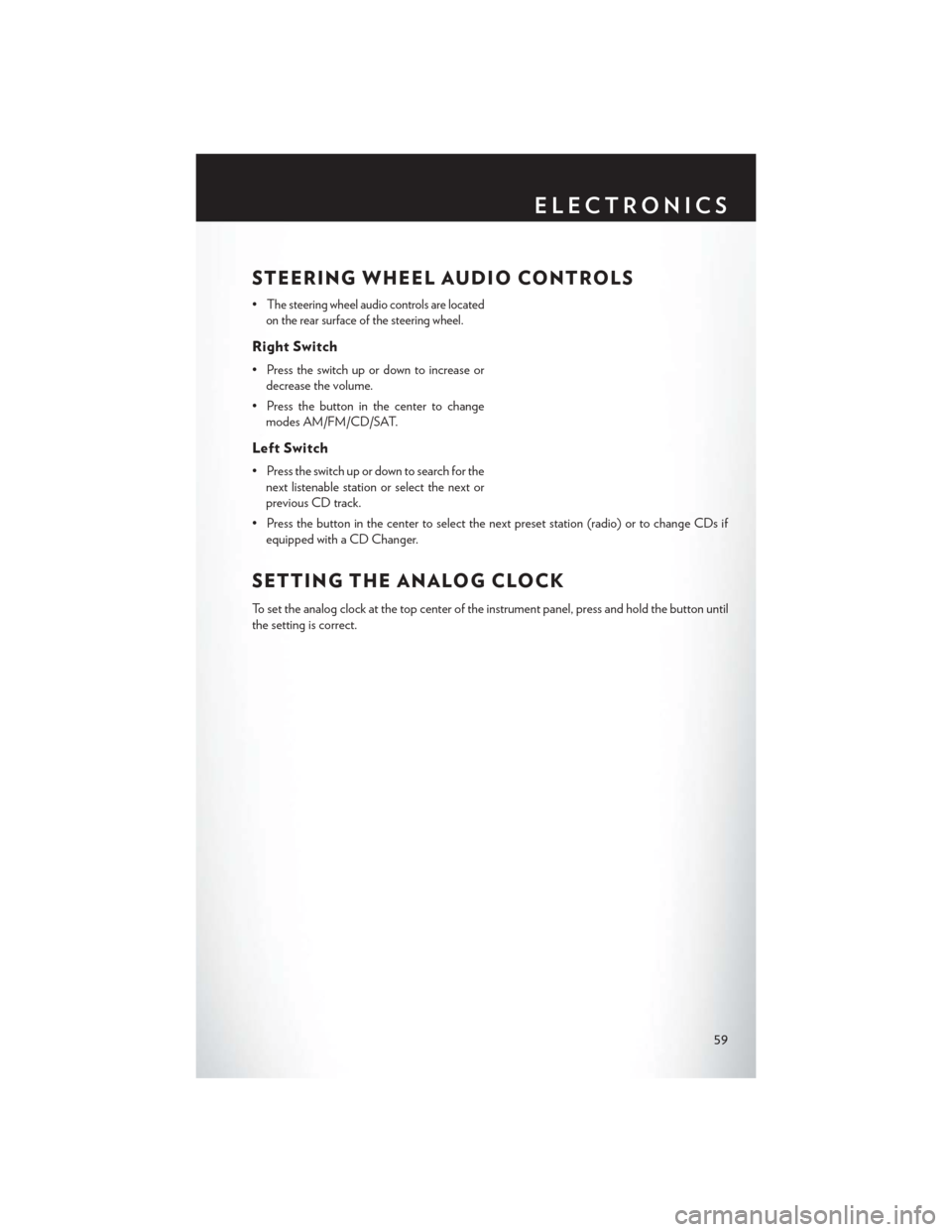
STEERING WHEEL AUDIO CONTROLS
•The steering wheel audio controls are located
on the rear surface of the steering wheel.
Right Switch
• Press the switch up or down to increase or decrease the volume.
• Press the button in the center to change modes AM/FM/CD/SAT.
Left Switch
• Press the switch up or down to search for thenext listenable station or select the next or
previous CD track.
• Press the button in the center to select the next preset station (radio) or to change CDs if equipped with a CD Changer.
SETTING THE ANALOG CLOCK
To set the analog clock at the top center of the instrument panel, press and hold the button until
the setting is correct.
ELECTRONICS
59
Page 74 of 116
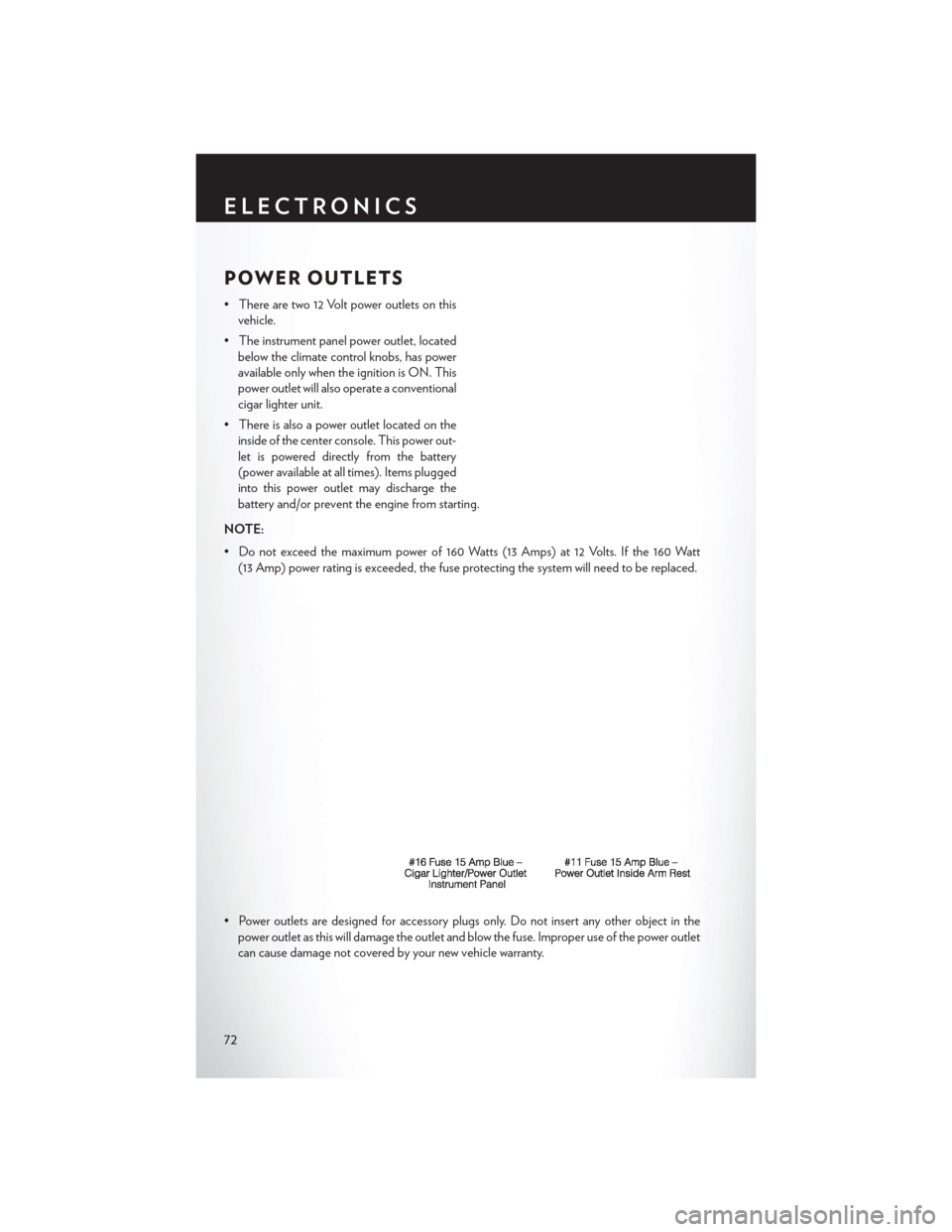
POWER OUTLETS
• There are two 12 Volt power outlets on thisvehicle.
• The instrument panel power outlet, located below the climate control knobs, has power
available only when the ignition is ON. This
power outlet will also operate a conventional
cigar lighter unit.
• There is also a power outlet located on the inside of the center console. This power out-
let is powered directly from the battery
(power available at all times). Items plugged
into this power outlet may discharge the
battery and/or prevent the engine from starting.
NOTE:
• Do not exceed the maximum power of 160 Watts (13 Amps) at 12 Volts. If the 160 Watt (13 Amp) power rating is exceeded, the fuse protecting the system will need to be replaced.
• Power outlets are designed for accessory plugs only. Do not insert any other object in the power outlet as this will damage the outlet and blow the fuse. Improper use of the power outlet
can cause damage not covered by your new vehicle warranty.
ELECTRONICS
72
Page 99 of 116
MAINTENANCE SCHEDULE
Your vehicle is equipped with an automatic oil change indicator system. The oil change indicator
system will remind you that it is time to take your vehicle in for scheduled maintenance.
Based on engine operation conditions, the oil change indicator message will illuminate. This
means that service is required for your vehicle. Operating conditions such as frequent short-trips,
trailer tow, extremely hot or cold ambient temperatures, and E85 fuel usage will influence when
the “Oil Change Required” message is displayed. Severe Operating Conditions can cause the
change oil message to illuminate as early as 3,500 miles (5,600 km) since last reset. Have your
vehicle serviced as soon as possible, within the next 500 miles (805 km).
Your authorized dealer will reset the oil change indicator message after completing the scheduled oil
change. If a scheduled oil change is performed by someone other than your authorized dealer, the
message can be reset by referring to the steps described under “Electronic Vehicle Information Center
(EVIC)/Oil Change Required” in “Understanding Your Instrument Panel” for further information.
NOTE:
Under no circumstances should oil change intervals exceed 10,000 miles (16,000 km) or twelve
months, whichever comes first.
Severe Duty All Models
Change Engine Oil at 4000 miles (6,500 km) if the vehicle is operated in a dusty and off road
environment. This type of vehicle use is considered Severe Duty.
Once A Month Or Before A Long Trip:
• Check engine oil level.
• Check windshield washer fluid level.
• Check tire pressure and look for unusual wear or damage. Rotate tires at the first sign ofirregular wear, even if it occurs before the oil indicator system turns on.
• Check the fluid levels of the coolant reservoir, brake master cylinder, power steering and transmission (four-speed only) and fill as needed.
• Check function of all interior and exterior lights.
Required Maintenance Intervals
Refer to the maintenance schedules on the following page for the required maintenance intervals.
At Every Oil Change Interval As Indicated By Oil Change Indicator System:
• Change oil and filter.
• Rotate the tires. Rotate at the first sign of irregular wear, even if it occurs before the oil
indicator system turns on.
• Inspect battery and clean and tighten terminals as required.
• Inspect automatic transmission fluid if equipped with dipstick.
• Inspect brake pads, shoes, rotors, drums, hoses and park brake.
• Inspect engine cooling system protection and hoses.
• Inspect exhaust system.
• Inspect engine air cleaner if using in dusty or off-road conditions.
MAINTAINING YOUR VEHICLE
97
Page 103 of 116
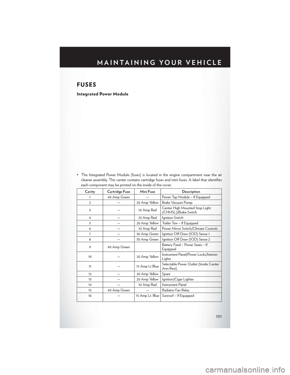
FUSES
Integrated Power Module
• The Integrated Power Module (fuses) is located in the engine compartment near the aircleaner assembly. This center contains cartridge fuses and mini fuses. A label that identifies
each component may be printed on the inside of the cover.
Cavity Cartridge Fuse Mini Fuse Description
1 40 Amp Green — Power Top Module – If Equipped
2 — 20 Amp Yellow Brake Vacuum Pump
3 — 10 Amp Red Center High Mounted Stop Light
(CHMSL)/Brake Switch
4 — 10 Amp Red Ignition Switch
5 — 20 Amp Yellow Trailer Tow – If Equipped
6 — 10 Amp Red Power Mirror Switch/Climate Controls
7 — 30 Amp Green Ignition Off Draw (IOD) Sense 1
8 — 30 Amp Green Ignition Off Draw (IOD) Sense 2
9 40 Amp Green Battery Feed – Power Seats – If
Equipped
10 — 20 Amp Yellow Instrument Panel/Power Locks/Interior
Lights
11 — 15 Amp Lt Blue Selectable Power Outlet (Inside Center
Arm Rest)
12 — 20 Amp Yellow Spare
13 — 20 Amp Yellow Ignition/Cigar Lighter
14 — 10 Amp Red Instrument Panel
15 40 Amp Green — Radiator Fan Relay
16 — 15 Amp Lt. Blue Sunroof – If Equipped
MAINTAINING YOUR VEHICLE
101