instrument panel CHRYSLER 200 2015 2.G Owner's Manual
[x] Cancel search | Manufacturer: CHRYSLER, Model Year: 2015, Model line: 200, Model: CHRYSLER 200 2015 2.GPages: 220, PDF Size: 3.7 MB
Page 39 of 220
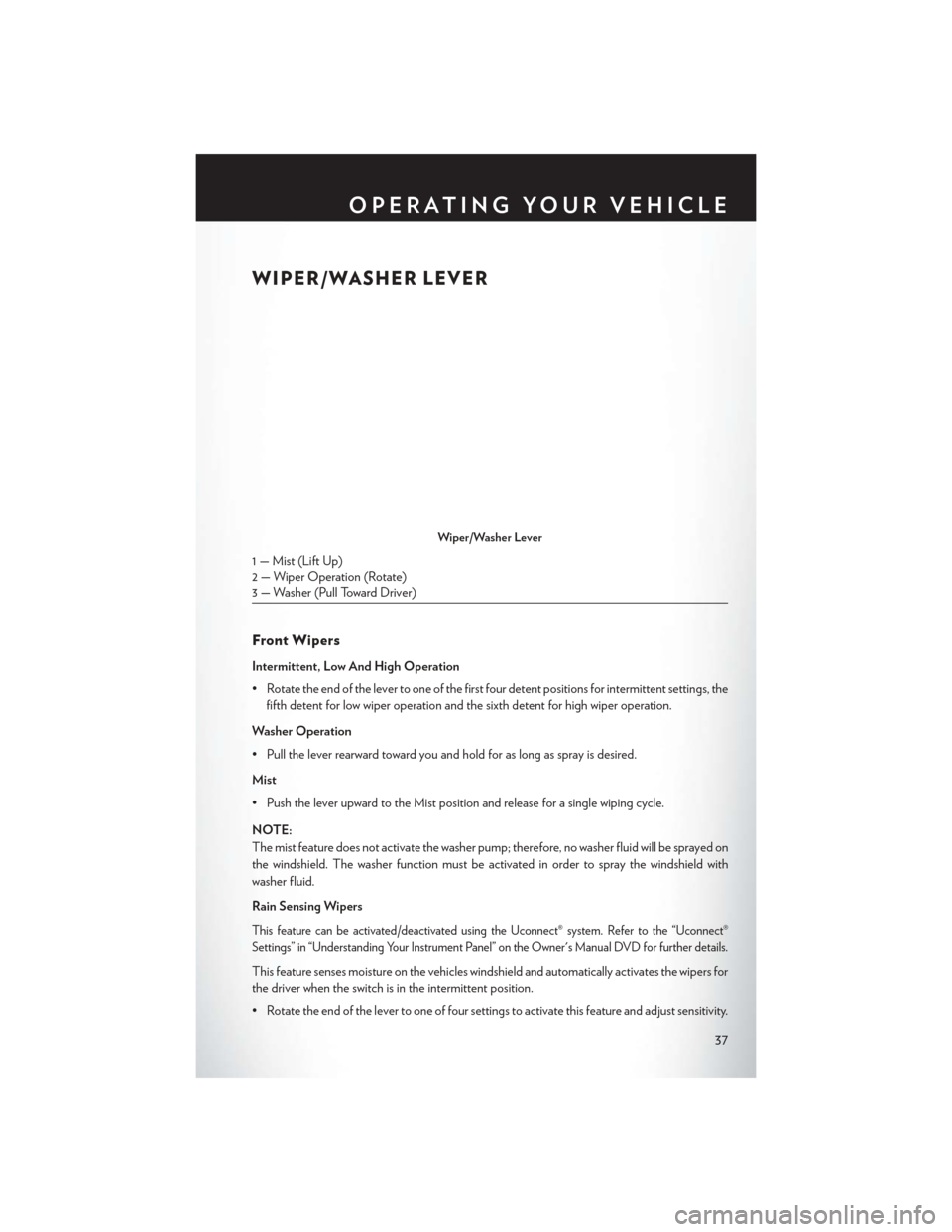
WIPER/WASHER LEVER
Front Wipers
Intermittent, Low And High Operation
• Rotate the end of the lever to one of the first four detent positions for intermittent settings, thefifth detent for low wiper operation and the sixth detent for high wiper operation.
Washer Operation
• Pull the lever rearward toward you and hold for as long as spray is desired.
Mist
• Push the lever upward to the Mist position and release for a single wiping cycle.
NOTE:
The mist feature does not activate the washer pump; therefore, no washer fluid will be sprayed on
the windshield. The washer function must be activated in order to spray the windshield with
washer fluid.
Rain Sensing Wipers
This feature can be activated/deactivated using the Uconnect® system. Refer to the “Uconnect®
Settings” in “Understanding Your Instrument Panel” on the Owner's Manual DVD for further details.
This feature senses moisture on the vehicles windshield and automatically activates the wipers for
the driver when the switch is in the intermittent position.
• Rotate the end of the lever to one of four settings to activate this feature and adjust sensitivity.
Wiper/Washer Lever
1 — Mist (Lift Up)
2 — Wiper Operation (Rotate)
3 — Washer (Pull Toward Driver)
OPERATING YOUR VEHICLE
37
Page 45 of 220
FORWARD COLLISION WARNING (FCW) WITH
MITIGATION
The Forward Collision Warning (FCW) system with mitigation provides the driver with audible
warnings, visual warnings (within the EVIC/DID), and may apply a brake jerk to warn the driver
when it detects a potential frontal collision. The warnings and limited braking are intended to
provide the driver with enough time to react, avoid or mitigate the potential collision.
NOTE:
FCW monitors the information from the forward looking sensors as well as the Electronic Brake
Controller (EBC), to calculate the probability of a forward collision. When the system determines
that a forward collision is probable, the driver will be provided with audible and visual warnings
and may provide a brake jerk warning. If the driver does not take action based upon these
progressive warnings, then the system will provide a limited level of active braking to help slow the
vehicle and mitigate the potential forward collision. If the driver reacts to the warnings by braking
and the system determines that the driver intends to avoid the collision by braking but has not
applied sufficient brake force, the system will compensate and provide additional brake force as
required.
Turning FCW ON Or OFF
NOTE:
The default status of FCW is “On”, this allows the system to warn you of a possible collision with
the vehicle in front of you when you are farther away and it applies limited braking. This gives you
the most reaction time to avoid a possible collision.
The forward collision button is on the switch panel that is located in the center of the instrument
panel.
•
To turn the FCW system OFF, press the for-
ward collision button once (LED turns on).
•To turn the FCW system back ON, press the
forward collision button again (LED turns off ).
Changing FCW Status
The FCW feature has two settings and can be
changed within the Uconnect® System Screen:
•Far
• Near
NOTE:
The FCW and active braking settings can only
be changed when the vehicle is in PARK.
Forward Collision Button
OPERATING YOUR VEHICLE
43
Page 56 of 220
STOP/START SYSTEM — 2.4L ENGINE
The Stop/Start function is developed to save fuel and reduce emissions. The system will stop the
engine automatically during a vehicle stop if the required conditions are met. Releasing the brake
pedal or pressing the accelerator pedal on an automatic transmission will start the engine.
Automatic Mode
The Stop/Start feature is enabled after every normal customer engine start. It will remain in
STOP/START NOT READY until you drive forward with a vehicle speed greater than 5 mph
(8 km/h). At that time, the system will go into STOP/START READY and if all other conditions
are met, can go into a STOP/START AUTOSTOP ACTIVE “Autostop” mode.
To Activate The Autostop Mode, The Following Must Occur:
• The system must be in STOP/START READY state. A STOP/START READY message willbe displayed in the Electronic Vehicle Information Center (EVIC) or Driver Information
Display (DID) within the Stop/Start section. Refer to “Electronic Vehicle Information Center
(EVIC)” or “Driver Information Display (DID)” in “Understanding Your Instrument Panel” in
your owners manual on the DVD for further information.
• The vehicle must be completely stopped.
• The shifter must be in DRIVE or NEUTRAL and the brake pedal depressed.
The engine will shut down, the tachometer will move to the zero position and the Stop/Start
telltale will illuminate indicating you are in Autostop. While in Autostop, the Climate Controls
system may automatically adjust airflow to maintain cabin comfort. Customer settings will be
maintained upon return to an engine running condition.
Refer to the “Stop/Start System” in the “Starting and Operating” section located in your owners
manual on the DVD for further information.
To Manually Turn Off The Stop/Start System
1. Press the STOP/START Off switch (located on the switch bank). The light on the switch will illuminate.
2. The “STOP/START OFF” message will ap- pear in Electronic Vehicle Information Cen-
ter (EVIC) or Driver Information Display
(DID). Refer to “Electronic Vehicle Infor-
mation Center (EVIC)” or “Driver Informa-
tion Display (DID)” in “Understanding Your
Instrument Panel” your owners manual on
the DVD for further information.
3. At the next vehicle stop (after turning off the STOP/START system) the engine will
not be stopped.
4. The STOP/START system will reset itself back to an ON condition every time the key is turned off and back on.
STOP/START OFF Switch
OPERATING YOUR VEHICLE
54
Page 62 of 220
PARKVIEW® REAR BACK-UP CAMERA
You can see an on-screen image of the rear of your vehicle whenever the shift lever is put into
REVERSE. The ParkView® Rear Back-Up Camera image will be displayed on the radio display
screen, located on the center stack of the instrument panel.
If the radio display screen appears foggy, clean the camera lens located on the rear of the vehicle
above the rear license plate.
Refer to your Owner's Manual on the DVD for further details.
WARNING!
Drivers must be careful when backing up; even when using the ParkView® Rear Back-Up
Camera. Always check carefully behind your vehicle, and be sure to check for pedestrians,
animals, other vehicles, obstructions, or blind spots before backing up. You must continue to
pay attention while backing up. Failure to do so can result in serious injury or death.
BLIND SPOT MONITORING
The Blind Spot Monitoring (BSM) system uses two radar-based sensors, located inside the rear
bumper fascia, to detect Highway licensable vehicles (automobiles, trucks, motorcycles etc.) that
enter the blind spot zones from the rear/front/side of the vehicle.
The Blind Spot Monitoring (BSM) system warning light, located in the outside mirrors, will
illuminate if a vehicle moves into a blind spot zone.
The BSM system can also be configured to sound an audible (chime) alert and mute the radio to
notify you of objects that have entered the detection zones.
Refer to your Owner's Manual on the DVD for further details.
OPERATING YOUR VEHICLE
60
Page 76 of 220
Selling Your Vehicle
When you sell your vehicle, we recommend that you remove your Uconnect® Access Account
information from the vehicle. You can do this using the radio touchscreen in the vehicle or on the
Mopar Owner Connect website (moparownerconnect.com). Removing your account informa-
tion cancels your subscription and makes your vehicle factory-ready for a new owner/subscriber.
1. From your vehicle’s radio touchscreen, select “Uconnect® Store” from the Apps Menu.
2. Select “My Apps,” then “Settings.” Press “Remove Uconnect® Account.”
3. Enter your Uconnect® Security PIN, and select “Continue.”
For additional information on Uconnect®:
• U.S. residents - visit DriveUconnect.com or call 1-877-855-8400.
• Canadian Residents - visit DriveUconnect.ca or call, 1-800-465-2001 (English) or1-800-387-9983 (French).
Built-In Features (Uconnect® 8.4AN Only)
CAUTION!
• Ignoring the rearview mirror light could mean you may not have 9-1-1 Call service if needed. If the rearview mirror light is illuminated, have an authorized dealer service the
9-1-1 Call system immediately.
• The Occupant Restraint Controller (ORC) turns on the Air Bag Warning Light on the
instrument panel if a malfunction is detected in any part of the air bag system. If the Air
Bag Warning Light is illuminated, the air bag system may not be working properly and the
9-1-1 system may not be able to send a signal to a 9-1-1 operator. If the Air Bag Warning
Light is illuminated, have an authorized dealer service your vehicle immediately.
• If anyone in the vehicle could be in danger (e.g., fire or smoke is visible, dangerous road
conditions or location), do not wait for voice contact from a 9-1-1 operator. All occupants
should exit the vehicle immediately and move to a safe location.
• Do not add any aftermarket electrical equipment to the vehicle’s electrical system. This
may prevent your vehicle from sending a signal to initiate an emergency call. To avoid
interference that can cause the 9-1-1 Call system to fail, never add aftermarket equipment
(e.g., two-way mobile radio, CB radio, data recorder, etc.) to your vehicle’s electrical
system or modify the antennas on your vehicle. IF YOUR VEHICLE LOSES BATTERY
POWER FOR ANY REASON (INCLUDING DURING OR AFTER AN ACCI-
DENT), THE UCONNECT® FEATURES, APPS AND SERVICES, AMONG OTH-
ERS, WILL NOT OPERATE.
ELECTRONICS
74
Page 150 of 220
PROGRAMMABLE FEATURES
Uconnect® Customer Programmable Features
The Uconnect® system allows you to access Customer Programmable feature settings such as
Display, Clock, Safety/Assistance, Lights, Doors & Locks, Auto-On Comfort & Remote Start,
Engine Off Operation, Compass Settings, Audio, Trailer Brake, Phone/Bluetooth®, Suspension
and SiriusXM Setup and System Information through buttons on the touchscreen.
• Push the “Controls” button located near the bottom of the touchscreen, then push the“Settings” button on the touchscreen to access the Settings screen. When making a selection,
scroll up or down until the preferred setting is highlighted, then press and release the preferred
setting until a check-mark appears next to the setting, showing that setting has been selected.
The following feature settings are available:
• Display • Voice
• Units • Doors & Locks
• Safety/Assistance • Engine Off Options
• Auto-On Comfort & Remote Start • Audio
• Phone/Bluetooth® • SiriusXM Setup
• Lights • System Information
• Clock • Compass
Refer to “Uconnect Settings/Customer Programmable Features” found within “Understanding
Your Instrument Panel” located in your Owner's Manual on the DVD for further information.
UNIVERSAL GARAGE DOOR OPENER
(HomeLink®)
HomeLink® replaces up to three hand-held
transmitters that operate devices such as ga-
rage door openers, motorized gates, lighting or
home security systems. The HomeLink® unit is
powered by your vehicles 12 Volt battery.
The HomeLink® buttons that are located in the
overhead console or sunvisor designate the
three different HomeLink® channels.
The HomeLink® indicator is located above the
center button.
Homelink® Indicator
ELECTRONICS
148
Page 167 of 220
If the sealant (white fluid) does not flow within0–10seconds through the Sealant Hose (6):
1. Press the Power Button (4) to turn Off the Tire Service Kit. Disconnect the Sealant Hose (6) from the valve stem. Make sure the valve stem is free of debris. Reconnect the Sealant
Hose (6) to the valve stem. Check that the Mode Select Knob (5) is in the Sealant Mode
position and not Air Mode. Press the Power Button (4) to turn On the Tire Service Kit.
2. Connect the Power Plug (8) to a different 12 Volt power outlet in your vehicle or another vehicle, if available. Make sure the engine is running before turning ON the Tire Service Kit.
3. The Sealant Bottle (1) may be empty due to previous use. Call for assistance.
NOTE:
If the Mode Select Knob (5) is on Air Mode and the pump is operating, air will dispense from the
Air Pump Hose (7) only, not the Sealant Hose (6).
If the sealant (white fluid) does flow through the Sealant Hose (6):
1. Continue to operate the pump until sealant is no longer flowing through the hose (typically takes 30 - 70 seconds). As the sealant flows through the Sealant Hose (6), the Pressure Gauge
(3) can read as high as 70 psi (4.8 Bar). The Pressure Gauge (3) will decrease quickly from
approximately 70 psi (4.8 Bar) to the actual tire pressure when the Sealant Bottle (1) is empty.
2. The pump will start to inject air into the tire immediately after the Sealant Bottle (1) is empty. Continue to operate the pump and inflate the tire to the pressure indicated on the tire pressure
label on the driver-side latch pillar (recommended pressure). Check the tire pressure by
looking at the Pressure Gauge (3).
If the tire does not inflate to at least 26 psi (1.8 Bar) pressure within 15 minutes:
The tire is too badly damaged. Do not attempt to drive the vehicle further. Call for assistance.
NOTE:
If the tire becomes over-inflated, press the Deflation Button to reduce the tire pressure to the
recommended inflation pressure before continuing.
If the tire inflates to the recommended pressure or is at least 26 psi (1.8 Bar) pressure within
15 minutes:
1. Press the Power Button (4) to turn off the Tire Service Kit.
2. Remove the Speed Limit sticker from the top of the Sealant Bottle (1) and place the sticker on the instrument panel.
3. Immediately disconnect the Sealant Hose (6) from the valve stem, reinstall the cap on the fitting at the end of the hose, and place the Tire Service Kit in the vehicle storage location.
Quickly proceed to (D) “Drive Vehicle.”
(D) Drive Vehicle:
Immediately after injecting sealant and inflating the tire, drive the vehicle 5 miles (8 km) or
10 minutes to ensure distribution of the Tire Service Kit Sealant within the tire. Do not exceed
55 mph (88 km/h).
WHAT TO DO IN EMERGENCIES
165
Page 168 of 220
(E) After Driving:
Pull over to a safe location. Refer to “Whenever You Stop to Use Tire Service Kit” before
continuing.
1. Turn the Mode Select Knob (5) to the Air Mode position.
2. Uncoil the Air Pump Hose (7) (black in color) and screw the fitting at the end of hose (7) ontothe valve stem.
3. Uncoil the power plug and insert the plug into the vehicles 12 Volt power outlet.
4. Check the pressure in the tire by reading the Pressure Gauge (3).
If tire pressure is less than 19 psi (1.3 Bar), the tire is too badly damaged. Do not attempt to
drive the vehicle further. Call for assistance.
If the tire pressure is 19 psi (1.3 Bar) or higher:
1. Press the Power Button (4) to turn on Tire Service Kit and inflate the tire to the pressure indicated on the tire and loading information label on the driver-side door opening.
2. Disconnect the Tire Service Kit from the valve stem, reinstall the cap on the valve stem and unplug from 12 Volt outlet.
3. Place the Tire Service Kit in its proper storage area in the vehicle.
4. Have the tire inspected and repaired or replaced at the earliest opportunity at an authorized dealer or tire service center.
5. Remove the Speed Limit sticker from the instrument panel after the tire has been repaired.
6. Replace the Sealant Bottle (1) and Sealant Hose (6) assembly at your authorized dealer as soon as possible. Refer to “(F) Sealant Bottle and Hose Replacement.”
NOTE:
• If the tire becomes over-inflated, press the Deflation Button to reduce the tire pressure to the recommended inflation pressure before continuing.
• When having the tire serviced, advise the authorized dealer or service center that the tire has been sealed using the Tire Service Kit.
(F) Sealant Bottle And Hose Replacement:
1. Uncoil the Sealant Hose (6) (clear in color).
2. Locate the round Sealant Bottle release button in the recessed area under the sealant bottle.
3. Press the Sealant Bottle release button. The Sealant Bottle (1) will pop up. Remove the bottle
and dispose of it accordingly.
4. Clean any remaining sealant from the Tire Service Kit housing.
5. Position the new Sealant Bottle (1) in the housing so that the Sealant Hose (6) aligns with the hose slot in the front of the housing. Press the bottle into the housing. An audible click will be
heard indicating the bottle is locked into place.
WHAT TO DO IN EMERGENCIES
166
Page 184 of 220
OPENING THE HOOD
To open the hood, two levers must be released:
1. Pull the hood release lever located under the driver side of the instrument panel.
Release Lever
Safety Latch Lever Location
MAINTAINING YOUR VEHICLE
182
Page 192 of 220
MAINTENANCE SCHEDULE
Your vehicle is equipped with an automatic oil change indicator system. The oil change indicator
system will remind you that it is time to take your vehicle in for scheduled maintenance.
Based on engine operation conditions, the oil change indicator message will illuminate. This
means that service is required for your vehicle. Operating conditions such as frequent short-trips,
trailer tow, extremely hot or cold ambient temperatures will influence when the “Oil Change
Required” message is displayed. Severe Operating Conditions can cause the change oil message
to illuminate as early as 3,500 miles (5,600 km) since last reset. Have your vehicle serviced as soon
as possible, within the next 500 miles (805 km).
Your authorized dealer will reset the oil change indicator message after completing the scheduled oil
change. If a scheduled oil change is performed by someone other than your authorized dealer, the
message can be reset by referring to the steps described under “Oil Change Reset” in “Electronic
Vehicle Information Center (EVIC)” or "Driver Information Display (DID)” in “Understanding Your
Instrument Panel” in your Owners Manual on the DVD for further information.
NOTE:
Under no circumstances should oil change intervals exceed 10,000 miles (16,000 km) or twelve
months, whichever comes first.
Severe Duty All Models
Change Engine Oil at 4000 miles (6,500 km) if the vehicle is operated in a dusty and off road
environment. This type of vehicle use is considered Severe Duty.
Once A Month Or Before A Long Trip:
• Check engine oil level.
• Check windshield washer fluid level.
• Check tire pressure and look for unusual wear or damage. Rotate tires at the first sign ofirregular wear, even if it occurs before the oil indicator system turns on.
• Check the fluid levels of the coolant reservoir and brake master cylinder, fill as needed.
• Check function of all interior and exterior lights.
Required Maintenance Intervals.
Refer to the maintenance schedules on the following page for the required maintenance intervals.
At Every Oil Change Interval As Indicated By Oil Change Indicator System:
• Change oil and filter
• Rotate the tires. Rotate at the first sign of irregular wear, even if it occurs before the oil
indicator system turns on.
• Inspect battery and clean and tighten terminals as required
• Inspect brake pads, shoes, rotors, drums, hoses and park brake
• Inspect engine cooling system protection and hoses
• Inspect exhaust system
• Inspect engine air cleaner if using in dusty or off-road conditions
MAINTAINING YOUR VEHICLE
190