buttons CHRYSLER 200 2015 2.G User Guide
[x] Cancel search | Manufacturer: CHRYSLER, Model Year: 2015, Model line: 200, Model: CHRYSLER 200 2015 2.GPages: 220, PDF Size: 3.7 MB
Page 14 of 220
KEYLESS ENTER-N-GO™
The Keyless Enter-N-Go™ system is an enhancement to the vehicle's Key Fob. This feature
allows you to lock and unlock the vehicle's door(s) and trunk without having to push the Key Fob
lock or unlock buttons, as well as starting and stopping the vehicle with the push of a button.
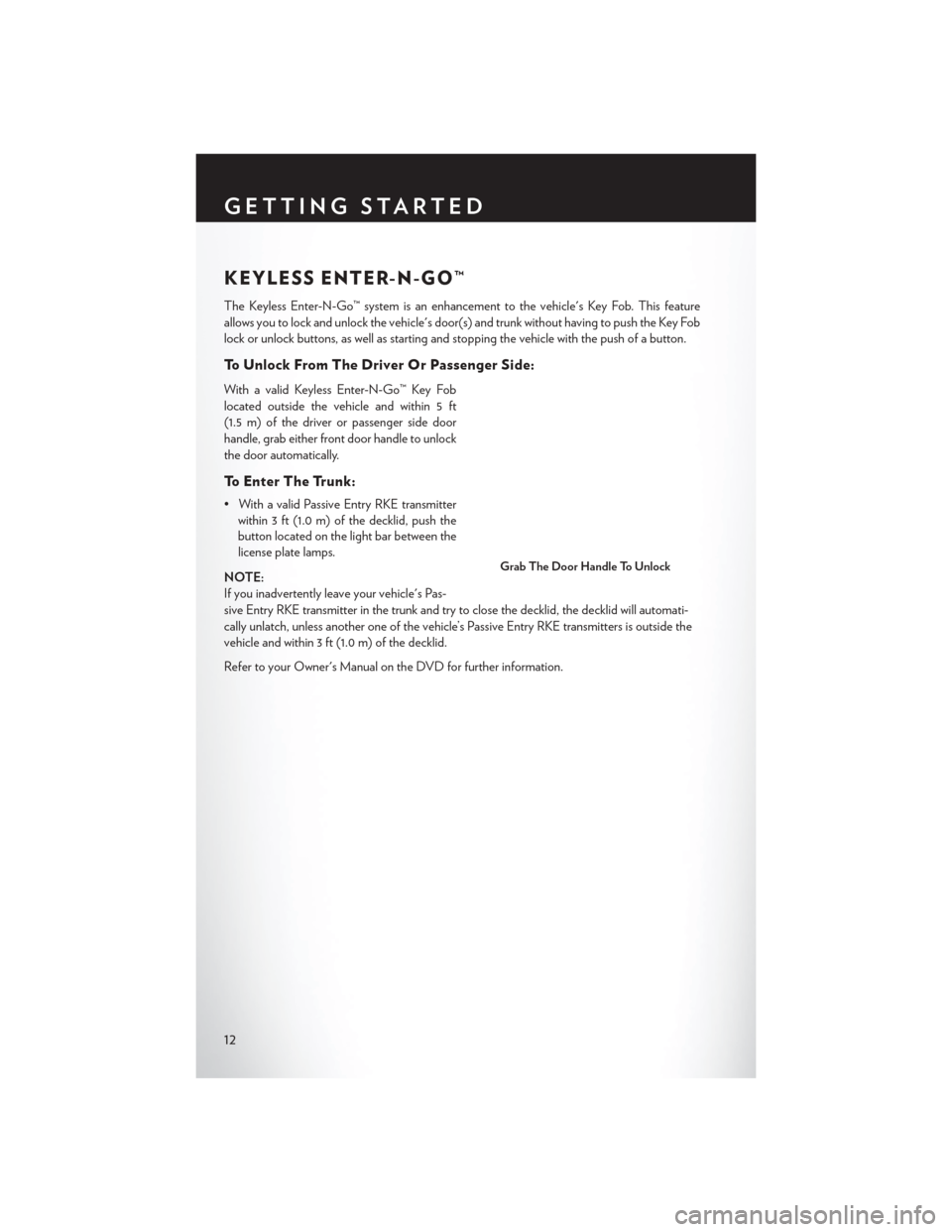
To Unlock From The Driver Or Passenger Side:
With a valid Keyless Enter-N-Go™ Key Fob
located outside the vehicle and within 5 ft
(1.5 m) of the driver or passenger side door
handle, grab either front door handle to unlock
the door automatically.
To Enter The Trunk:
• With a valid Passive Entry RKE transmitterwithin 3 ft (1.0 m) of the decklid, push the
button located on the light bar between the
license plate lamps.
NOTE:
If you inadvertently leave your vehicle's Pas-
sive Entry RKE transmitter in the trunk and try to close the decklid, the decklid will automati-
cally unlatch, unless another one of the vehicle’s Passive Entry RKE transmitters is outside the
vehicle and within 3 ft (1.0 m) of the decklid.
Refer to your Owner's Manual on the DVD for further information.
Grab The Door Handle To Unlock
GETTING STARTED
12
Page 15 of 220
To Lock The Vehicle:
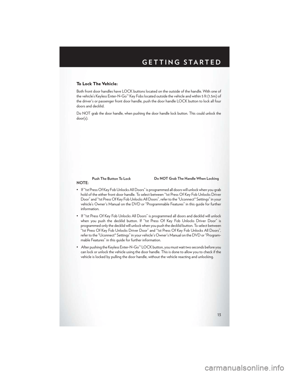
Both front door handles have LOCK buttons located on the outside of the handle. With one of
the vehicle’s Keyless Enter-N-Go™ Key Fobs located outside the vehicle and within 5 ft (1.5m) of
the driver's or passenger front door handle, push the door handle LOCK button to lock all four
doors and decklid.
Do NOT grab the door handle, when pushing the door handle lock button. This could unlock the
door(s).
NOTE:
• If “1st Press Of Key Fob Unlocks All Doors” is programmed all doors will unlock when you grabhold of the either front door handle. To select between “1st Press Of Key Fob Unlocks Driver
Door” and “1st Press Of Key Fob Unlocks All Doors”, refer to the “Uconnect® Settings” in your
vehicle’s Owner's Manual on the DVD or “Programmable Features” in this guide for further
information.
• If “1st Press Of Key Fob Unlocks All Doors” is programmed all doors and decklid will unlock when you push the decklid button. If “1st Press Of Key Fob Unlocks Driver Door” is
programmed only the decklid will unlock when you push the decklid button. To select between
“1st Press Of Key Fob Unlocks Driver Door” and “1st Press Of Key Fob Unlocks All Doors”,
refer to the “Uconnect® Settings” in your vehicle's Owner's Manual on the DVD or “Program-
mable Features” in this guide for further information.
• After pushing the Keyless Enter-N-Go™ LOCK button, you must wait two seconds before you can lock or unlock the vehicle using the door handle. This is done to allow you to check if the
vehicle is locked by pulling the door handle, without the vehicle reacting and unlocking.Push The Button To LockDo NOT Grab The Handle When Locking
GETTING STARTED
13
Page 31 of 220
Rear Head Restraints
The rear outboard head restraints have three positions UP, MID and DOWN. The center head
restraint has only two positions, Up and Down. When the center seat is being occupied the head
restraint should be in the raised position. When there are no occupants in the center seat the head
restraint can be lowered for maximum visibility for the driver.
To raise the head restraint, pull upward on the head restraint. To lower the head restraint, press the
push button, located at the base of the head restraint, and push downward on the head restraint.
FRONT SEATS
Power Seats
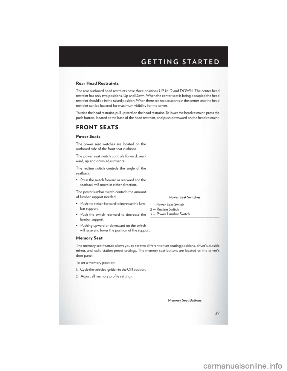
The power seat switches are located on the
outboard side of the front seat cushions.
The power seat switch controls forward, rear-
ward, up and down adjustments.
The recline switch controls the angle of the
seatback.
• Press the switch forward or rearward and theseatback will move in either direction.
The power lumbar switch controls the amount
of lumbar support needed.
• Push the switch forward to increase the lum- bar support.
• Push the switch rearward to decrease the lumbar support.
• Pushing upward or downward on the switch will raise and lower the position of the support.
Memory Seat
The memory seat feature allows you to set two different driver seating positions, driver's outside
mirror, and radio station preset settings. The memory seat buttons are located on the driver's
door panel.
To set a memory position:
1.
Cycle the vehicles ignition to the ON position.
2. Adjust all memory profile settings.
Power Seat Switches
1 — Power Seat Switch
2 — Recline Switch
3 — Power Lumbar Switch
Memory Seat Buttons
GETTING STARTED
29
Page 34 of 220
WARNING!
• Be certain that the seatback is securely locked into position. If the seatback is not securelylocked into position, the seat will not provide the proper stability for child seats and/or
passengers. An improperly latched seat could cause you and others to severely injured or
killed.
• The cargo area in the rear of the vehicle (with the rear seatbacks in the locked-up or
folded-down position) should not be used as a play area by children when the vehicle is in
motion. They could be severely injured or killed in a collision. Children should be seated
and using the proper restraint system.
HEATED/VENTILATED SEATS
Front Ventilated Seats
Located in the seat cushion and seatback are small fans that draw the air from the passenger
compartment and pull air through fine perforations in the seat cover to help keep the driver and
front passenger cooler in higher ambient temperatures.
There are two ventilated seat control buttons located in the touchscreen that allow the driver and
passenger to operate the seats independently.
The ventilated seat buttons are used to control the speed of the fans located in the seat.
To operate the system, press the “Controls” button on touchscreen located on the bottom of the
Uconnect® display.
• Press the ventilated seat button
once to choose HIGH.
• Press the ventilated seat button
a second time to choose LOW.
• Press the ventilated seat button
a third time to turn the ventilated seat OFF.
NOTE:
Vehicle Equipped With Remote Start
On models that are equipped with remote start, this feature can be programmed to come on
during a remote start through the Uconnect® system. Refer to “Uconnect® Settings” in “Under-
standing Your Instrument Panel” in the Owner's Manual on the DVD.
Front Heated Seats
The front heated seats control buttons are located within the climate or controls screen of the
touchscreen.
• Press the heated seat button
once to turn the High setting On.
• Press the heated seat button
a second time to turn the Low setting On.
• Press the heated seat button
a third time to turn the heating elements Off.
If the High-level setting is selected, the system will automatically switch to Low-level after
approximately 60 minutes. The Low-level setting will turn Off automatically after approximately
45 minutes.
GETTING STARTED
32
Page 35 of 220
NOTE:
Vehicle Equipped With Remote Start
On models that are equipped with remote start, this feature can be programmed to come on
during a remote start through the Uconnect® system. Refer to “Uconnect® Settings” in “Under-
standing Your Instrument Panel” in the Owner's Manual on the DVD.
WARNING!
• Persons who are unable to feel pain to the skin because of advanced age, chronic illness,diabetes, spinal cord injury, medication, alcohol use, exhaustion or other physical condi-
tions must exercise care when using the seat heater. It may cause burns even at low
temperatures, especially if used for long periods of time.
• Do not place anything on the seat that insulates against heat, such as a blanket or cushion.
This may cause the seat heater to overheat. Sitting in a seat that has been overheated
could cause serious burns due to the increased surface temperature of the seat.
HEATED STEERING WHEEL
The steering wheel contains a heating element that heats the steering wheel to one temperature
setting.
The heated steering wheel control button is located within the Uconnect® system. You can gain
access to the control buttons through the climate screen or the controls screen.
• Press the heated steering wheel button
once to turn the heating element ON.
• Press the heated steering wheel button
a second time to turn the heating element OFF.
Once the heated steering wheel has been turned on, it will operate for up to 80 minutes before
automatically shutting off. The heated steering wheel can shut off early or may not turn on when
the steering wheel is already warm.
NOTE:
Vehicle Equipped With Remote Start
On models that are equipped with remote start, this feature can be programmed to come on
during a remote start through the Uconnect® system. Refer to “Uconnect® Settings” in “Under-
standing Your Instrument Panel” in the Owner's Manual on the DVD.
WARNING!
• Persons who are unable to feel pain to the skin because of advanced age, chronic illness, diabetes, spinal cord injury, medication, alcohol use, exhaustion, or other physical condi-
tions must exercise care when using the steering wheel heater. It may cause burns even at
low temperatures, especially if used for long periods.
• Do not place anything on the steering wheel that insulates against heat, such as a blanket
or steering wheel covers of any type and material. This may cause the steering wheel
heater to overheat.
GETTING STARTED
33
Page 44 of 220
WARNING!
Adaptive Cruise Control (ACC) is a convenience system. It is not a substitute for active
driving involvement. It is always the driver’s responsibility to be attentive of road, traffic, and
weather conditions, vehicle speed, distance to the vehicle ahead; and, most importantly, brake
operation to ensure safe operation of the vehicle under all road conditions. Your complete
attention is always required while driving to maintain safe control of your vehicle. Failure to
follow these warnings can result in a collision and death or serious personal injury.
The ACC system:
• Does not react to pedestrians, oncoming vehicles, and stationary objects (e.g., a stopped
vehicle in a traffic jam or a disabled vehicle).
• Cannot take street, traffic, and weather conditions into account, and may be limited upon
adverse sight distance conditions.
• Does not always fully recognize complex driving conditions, which can result in wrong or
missing distance warnings.
• Will bring the vehicle to a complete stop while following a target vehicle and hold the
vehicle for 2 seconds in the stop position. If the target vehicle does not start moving within
two seconds the ACC system will display a message that the system will release the brakes
and that the brakes must be applied manually. An audible chime will sound when the
brakes are released.
You should switch off the ACC system:
• When driving in fog, heavy rain, heavy snow, sleet, heavy traffic, and complex driving
situations (i.e., in highway construction zones).
• When entering a turn lane or highway off ramp; when driving on roads that are winding, icy,
snow-covered, slippery, or have steep uphill or downhill slopes.
• When towing a trailer up or down steep slopes.
• When circumstances do not allow safe driving at a constant speed.
The Cruise Control system has two control modes:
• Adaptive Cruise Control mode for maintaining an appropriate distance between vehicles.
• Normal (fixed speed) electronic speed control mode for cruising at a constant preset
speed. For additional information, refer to “Normal (Fixed Speed) Cruise Control Mode”
in this section.
Normal (fixed speed) electronic speed control will not react to preceding vehicles. Always be
aware of the mode selected.
You can change the mode by using the Cruise Control buttons. The two control modes
function differently. Always confirm which mode is selected.
OPERATING YOUR VEHICLE
42
Page 68 of 220
IDENTIFYING YOUR RADIO
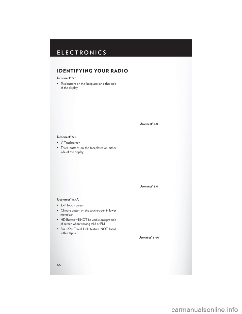
Uconnect® 3.0
• Two buttons on the faceplates on either sideof the display
Uconnect® 5.0
• 5” Touchscreen
• Three buttons on the faceplates on either side of the display
Uconnect® 8.4A
• 8.4” Touchscreen
• Climate button on the touchscreen in lower menu bar
• HD Button will NOT be visible on right side of screen when viewing AM or FM
• SiriusXM Travel Link feature NOT listed within Apps
Uconnect® 3.0
Uconnect® 5.0
Uconnect® 8.4A
ELECTRONICS
66
Page 70 of 220
Before you drive, familiarize yourself with the easy-to-use Uconnect® Access.
1. The ASSIST and 9-1-1 buttons are located on your rearview mirror. The ASSIST button is usedfor contacting Roadside Assistance, Vehicle Care and Uconnect® Care. The 9-1-1 button
connects you to emergency services.
NOTE:
Vehicles sold in Canada and Mexico DO NOT have 9-1-1 Call system capabilities. 9-1-1 or
other emergency line operators in Canada and Mexico may not answer or respond to 9-1-1
system calls.
2. The Uconnect® “Apps” button on the menu bar at the bottom right corner of the radio touchscreen. This is where you can begin your registration process, manage your Apps and
purchase WiFi on demand.
3. The Uconnect® Voice Command and Uconnect® Phone buttons are located on the left side of your steering wheel. These buttons let you use your voice to give commands, make phone
calls, send and receive text messages hands-free, enter navigation destinations, and control
your radio and media devices.
Included Trial Period For New Vehicles
Your new vehicle may come with an included trial period for use of the Uconnect® Access
Services starting at the date of vehicle purchase (date based on vehicle sales notification from
your dealer). To activate the trial, you must first register with Uconnect® Access. After the
trial period, if you wish to continue your Uconnect® Access Services you can choose to purchase
a subscription.
Features And Packages
• After the trial period, you can subscribe to continue your service by visiting the Uconnect® Store located within the Mopar Owner Connect website moparownerconnect.com. If you
need assistance, U.S. residents can call Uconnect® Care at 855-792-4241.
• For the latest information on packages and pricing information: U.S. residents visit DriveUconnect.com.
Uconnect® Access Registration (Uconnect® 8.4AN Only,
U.S. 48 Contiguous States, Alaska And Hawaii)
To unlock the full potential of Uconnect® Access in your vehicle, you first need to register with
Uconnect® Access.
1. From the parked vehicle with the radio touchscreen powered on, select the “Apps” button
located near the bottom right-hand corner of the radio touchscreen.
NOTE:
Should you require assistance anytime during the registration process, simply call Uconnect®
Care at 855-792-4241.
2. Press “Start” on the reminder screen or select “Uconnect Registration” under the “All Apps” or “Favorites Apps” tab on the Apps list.
ELECTRONICS
68
Page 77 of 220
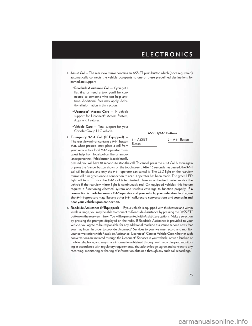
1.Assist Call – The rear view mirror contains an ASSIST push button which (once registered)
automatically connects the vehicle occupants to one of these predefined destinations for
immediate support:
•Roadside Assistance Call — If you get a
flat tire, or need a tow, you’ll be con-
nected to someone who can help any-
time. Additional fees may apply. Addi-
tional information in this section.
• Uconnect® Access Care — In vehicle
support for Uconnect® Access System,
Apps and Features.
• Vehicle Care — Total support for your
Chrysler Group LLC vehicle.
2. Emergency 9-1-1 Call (If Equipped) —
The rear view mirror contains a 9-1-1 button
that, when pressed, may place a call from
your vehicle to a local 9-1-1 operator to re-
quest help from local police, fire or ambu-
lance personnel. If this button is accidentally
pressed, you will have 10 seconds to stop the call. To cancel, press the 9-1-1 Call button again
or press the “cancel button shown on the touchscreen. After 10 seconds has passed, the 9-1-1
call will be placed and only the 9-1-1 operator can cancel it. The LED light on the rearview
mirror will turn green once a connection to a 9-1-1 operator has been made. The green LED
light will turn off once the 9-1-1 call is terminated. Have an authorized dealer service the
vehicle if the rearview mirror light is continuously red. On equipped vehicles, this feature
requires a functioning electrical system and wireless coverage to function properly. If a
connection is made between a 9-1-1 operator and your vehicle, you understand and agree
that 9-1-1 operators may, like any other 9-1-1 call, record conversations and sounds in and
near your vehicle upon connection.
3. Roadside Assistance (If Equipped) — If your vehicle is equipped with this feature and within
wireless range, you may be able to connect to Roadside Assistance by pressing the “ASSIST”
button on the rearview mirror. You will be presented with Assist Care options. Make a selection
by pressing the prompts displayed on the radio. If Roadside Assistance is provided to your
vehicle, you agree to be responsible for any additional roadside assistance service costs that
you may incur. In order to provide Uconnect® Services to you, we may record and monitor
your conversations with Roadside Assistance, Uconnect® Care or Vehicle Care, whether such
conversations are initiated through the Uconnect® Services in your vehicle, or via a landline or
mobile telephone, and may share information obtained through such recording and monitor-
ing in accordance with regulatory requirements. You acknowledge, agree and consent to any
recording, monitoring or sharing of information obtained through any such call recordings.
ASSIST/9-1-1 Buttons
1—ASSIST
Button2 — 9-1-1 Button
ELECTRONICS
75
Page 86 of 220
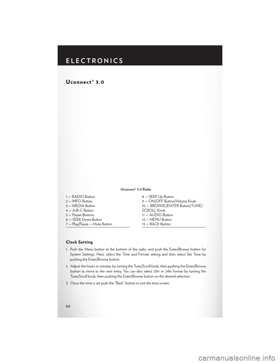
Uconnect® 3.0
Clock Setting
1. Push the Menu button at the bottom of the radio, and push the Enter/Browse button forSystem Settings. Next, select the Time and Format setting and then select Set Time by
pushing the Enter/Browse button.
2. Adjust the hours or minutes by turning the Tune/Scroll knob, then pushing the Enter/Browse button to move to the next entry. You can also select 12hr or 24hr format by turning the
Tune/Scroll knob, then pushing the Enter/Browse button on the desired selection.
3. Once the time is set push the “Back” button to exit the time screen.
Uconnect® 3.0 Radio
1 — RADIO Button
2 — INFO Button
3 — MEDIA Button
4 — A-B-C Button
5 — Preset Buttons
6 — SEEK Down Button
7 — Play/Pause — Mute Button8 — SEEK Up Button
9 — ON/OFF Button/Volume Knob
10 — BROWSE/ENTER Button/TUNE/
SCROLL Knob
11 — AUDIO Button
12 — MENU Button
13 — BACK Button
ELECTRONICS
84