stop start CHRYSLER 200 2015 2.G User Guide
[x] Cancel search | Manufacturer: CHRYSLER, Model Year: 2015, Model line: 200, Model: CHRYSLER 200 2015 2.GPages: 220, PDF Size: 3.7 MB
Page 3 of 220
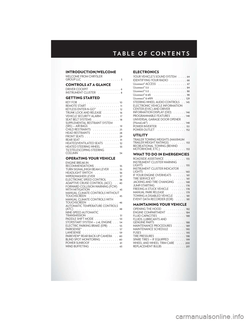
INTRODUCTION/WELCOME
WELCOME FROM CHRYSLER
GROUPLLC ..................3
CONTROLS AT A GLANCE
DRIVER COCKPIT...............6
INSTRUMENT CLUSTER ...........8
GETTING STARTED
KEYFOB ....................10
REMOTE START...............11
KEYLESS ENTER-N-GO™ ..........12
TRUNK LOCK AND RELEASE ........16
VEHICLE SECURITY ALARM ........17
SEAT BELT SYSTEMS .............18
SUPPLEMENTAL RESTRAINT SYSTEM
(SRS)—AIRBAGS ..............19
CHILD RESTRAINTS .............25
HEAD RESTRAINTS .............28
FRONTSEATS .................29
REAR SEAT ...................31
HEATED/VENTILATED SEATS .......32
HEATED STEERING WHEEL ........33
TILT/TELESCOPING STEERING
COLUMN ...................34
OPERATING YOUR VEHICLE
ENGINE BREAK-IN
RECOMMENDATIONS ............35
TURN SIGNAL/HIGH BEAM LEVER ....35
HEADLIGHT SWITCH ............36
WIPER/WASHER LEVER ...........37
ELECTRONIC SPEED CONTROL .....38
ADAPTIVE CRUISE CONTROL (ACC) . . 40
FORWARD COLLISION WARNING (FCW)
WITHMITIGATION .............43
MANUAL CLIMATE CONTROLS WITHOUT
TOUCHSCREEN ...............45
MANUAL CLIMATE CONTROLS WITH
TOUCHSCREEN ...............46
AUTOMATIC TEMPERATURE CONTROLS
(ATC) .....................48
NINE-SPEED AUTOMATIC
TRANSMISSION ................51
PADDLE SHIFT MODE ............53
STOP/START SYSTEM — 2.4L ENGINE . . . 54
ELECTRIC PARKING BRAKE (EPB) .....55
PARKSENSE® ..................57
LANESENSE . .................59
PARKVIEW® REAR BACK-UP CAMERA . . 60
BLIND SPOT MONITORING ........60
POWER SUNROOF ..............61
WIND BUFFETING . . ............63
ELECTRONICS
YOUR VEHICLE'S SOUND SYSTEM . . . . 64
IDENTIFYING YOUR RADIO ........66
Uconnect® ACCESS . . . ...........67
Uconnect® 3.0 . . ................84
Uconnect® 5.0 ..................86
Uconnect® 8.4A ................98
Uconnect® 8.4AN . . .............129
STEERING WHEEL AUDIO CONTROLS. . 145
ELECTRONIC VEHICLE INFORMATION
CENTER (EVIC) AND DRIVER
INFORMATION DISPLAY (DID) ......146
PROGRAMMABLE FEATURES .......148
UNIVERSAL GARAGE DOOR OPENER
(HomeLink®) ..................148
POWER INVERTER .............151
POWER OUTLET ..............152
UTILITY
TRAILER TOWING WEIGHTS (MAXIMUM
TRAILER WEIGHT RATINGS) .......153
RECREATIONAL TOWING (BEHIND
MOTORHOME, ETC.) ...........153
WHAT TO DO IN EMERGENCIES
ROADSIDE ASSISTANCE ..........155
INSTRUMENT CLUSTER WARNING
LIGHTS ....................155
INSTRUMENT CLUSTER INDICATOR
LIGHTS ....................160
IF YOUR ENGINE OVERHEATS ......161
TIRESERVICEKIT ..............161
JACKING AND TIRE CHANGING ....168
JUMP-STARTING ..............176
FREEING A STUCK VEHICLE .......178
MANUAL PARK RELEASE ..........179
TOWING A DISABLED VEHICLE .....181
EVENT DATA RECORDER (EDR) .....181
MAINTAINING YOUR VEHICLE
OPENING THE HOOD...........182
ENGINE COMPARTMENT .........184
FLUIDCAPACITIES .............188
FLUIDS, LUBRICANTS AND
GENUINE PARTS ..............188
MAINTENANCE PROCEDURES ......189
MAINTENANCE SCHEDULE .......190
FUSES .....................193
TIRE PRESSURES ...............198
SPARE TIRES — IF EQUIPPED .......199
WHEEL AND WHEEL TRIM CARE . . . . 200
REPLACEMENT BULBS ...........201
TABLE OF CONTENTS
Page 8 of 220
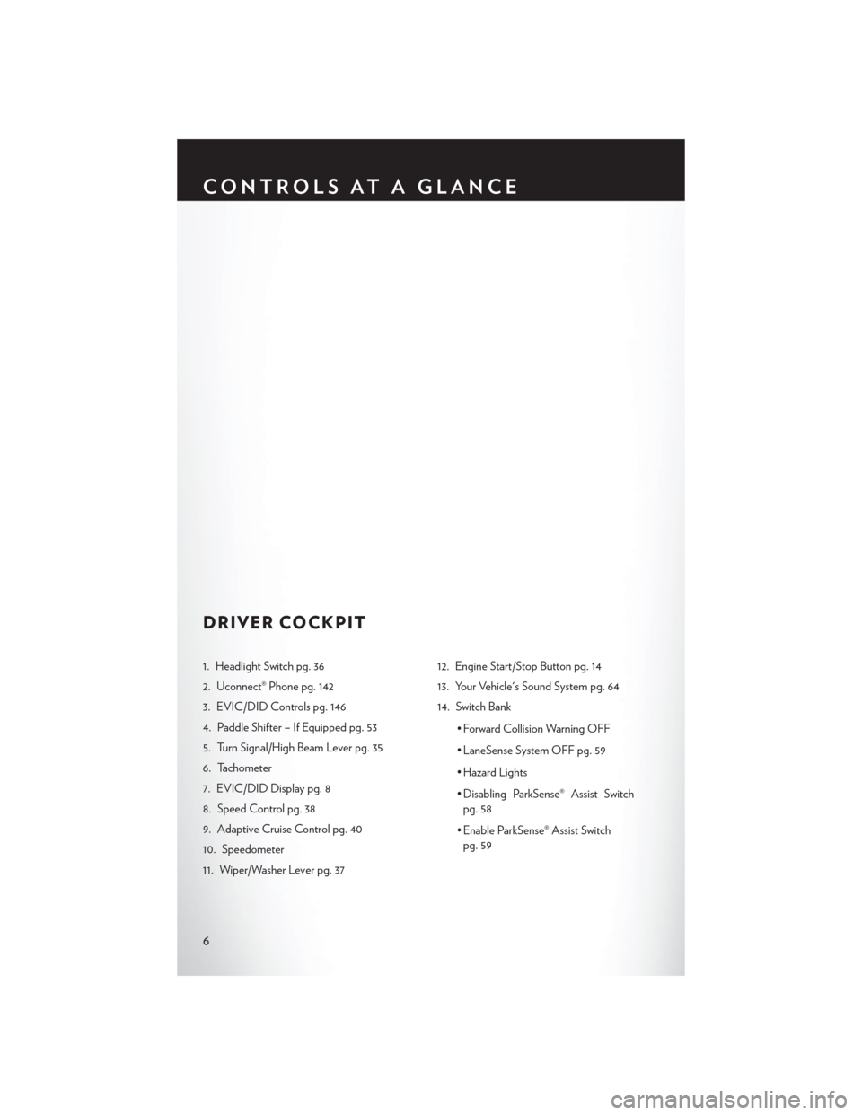
DRIVER COCKPIT
1. Headlight Switch pg. 36
2. Uconnect® Phone pg. 142
3. EVIC/DID Controls pg. 146
4. Paddle Shifter – If Equipped pg. 53
5. Turn Signal/High Beam Lever pg. 35
6. Tachometer
7. EVIC/DID Display pg. 8
8. Speed Control pg. 38
9. Adaptive Cruise Control pg. 40
10. Speedometer
11. Wiper/Washer Lever pg. 3712. Engine Start/Stop Button pg. 14
13. Your Vehicle's Sound System pg. 64
14. Switch Bank
• Forward Collision Warning OFF
• LaneSense System OFF pg. 59
• Hazard Lights
• Disabling ParkSense® Assist Switchpg. 58
• Enable ParkSense® Assist Switch pg. 59
CONTROLS AT A GLANCE
6
Page 12 of 220
KEY FOB
This feature allows the driver to operate the
ignition switch with the push of a button, as
long as the Remote Keyless Entry (RKE) trans-
mitter is in the passenger compartment.
The Keyless Ignition Node (KIN) has four op-
erating positions, three of which are labeled
and will illuminate when in position. The three
positions are OFF, ACC, and ON/RUN. The
fourth position is START, during start, RUN
will illuminate.
NOTE:
In case the ignition switch does not change with
the push of a button, the RKE transmitter (Key
Fob) may have a low or dead battery. In this
situation a back up method can be used to
operate the ignition switch. Put the nose side
(side opposite of the emergency key) of the
Key Fob against the ENGINE START/STOP
button and push to operate the ignition switch.
Locking And Unlocking The Doors
Push and release the LOCK button on the RKE
transmitter to lock all doors. The turn signal lights will flash and the horn will chirp to acknowledge
the signal.
Push and release the UNLOCK button on the RKE transmitter once to unlock the driver's door
or twice within five seconds to unlock all doors. The turn signal lights will flash to acknowledge the
unlock signal. The illuminated entry system will also turn on.
1st Press Of Key Fob Unlocks
This feature lets you program the system to unlock either the driver's door or all doors on the first
push of the UNLOCK button on the RKE transmitter. To change the current setting, refer to your
Owner's Manual on the DVD for further information.
Opening The Trunk
• Push the Trunk Release button on the transmitter two times within five seconds to open thetrunk.
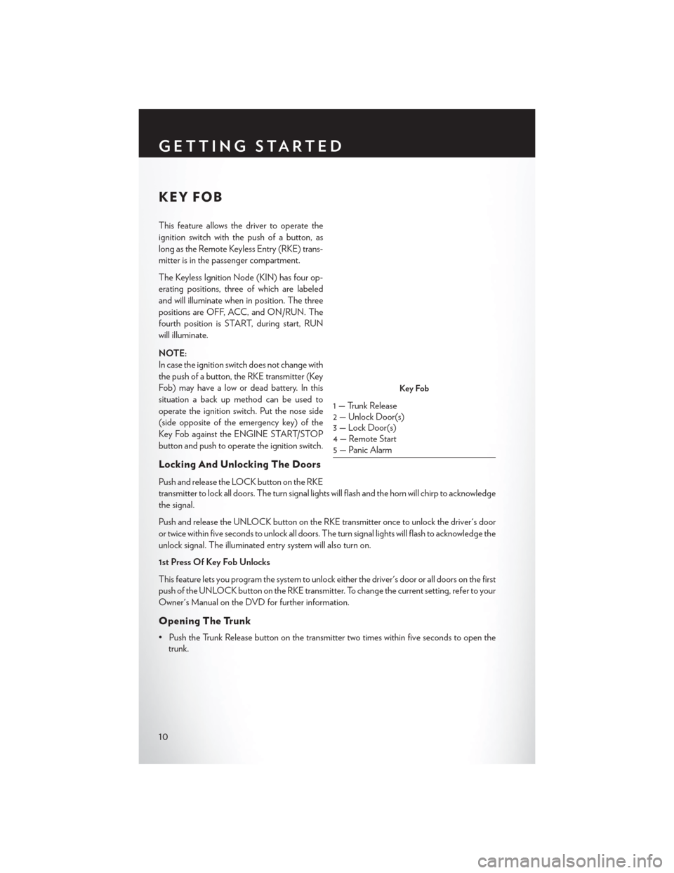
Key Fob
1 — Trunk Release
2 — Unlock Door(s)
3 — Lock Door(s)
4 — Remote Start
5 — Panic Alarm
GETTING STARTED
10
Page 14 of 220
KEYLESS ENTER-N-GO™
The Keyless Enter-N-Go™ system is an enhancement to the vehicle's Key Fob. This feature
allows you to lock and unlock the vehicle's door(s) and trunk without having to push the Key Fob
lock or unlock buttons, as well as starting and stopping the vehicle with the push of a button.
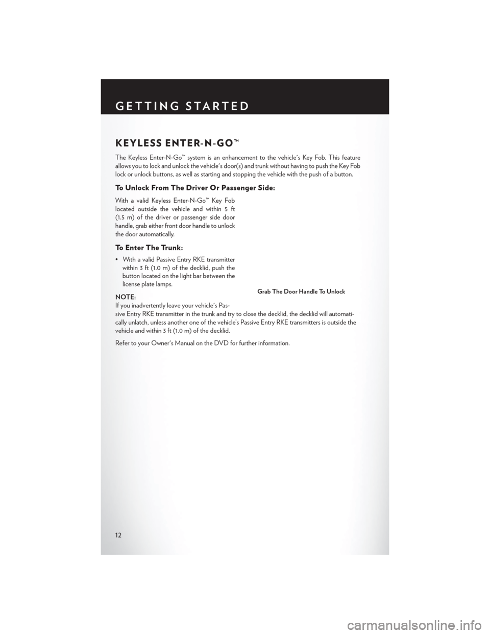
To Unlock From The Driver Or Passenger Side:
With a valid Keyless Enter-N-Go™ Key Fob
located outside the vehicle and within 5 ft
(1.5 m) of the driver or passenger side door
handle, grab either front door handle to unlock
the door automatically.
To Enter The Trunk:
• With a valid Passive Entry RKE transmitterwithin 3 ft (1.0 m) of the decklid, push the
button located on the light bar between the
license plate lamps.
NOTE:
If you inadvertently leave your vehicle's Pas-
sive Entry RKE transmitter in the trunk and try to close the decklid, the decklid will automati-
cally unlatch, unless another one of the vehicle’s Passive Entry RKE transmitters is outside the
vehicle and within 3 ft (1.0 m) of the decklid.
Refer to your Owner's Manual on the DVD for further information.
Grab The Door Handle To Unlock
GETTING STARTED
12
Page 16 of 220
Engine Starting/Stopping
Starting
With a valid Keyless Enter-N-Go™ Key Fob inside the vehicle:
1. While pushing the brake pedal, push the ENGINE START/STOP button once. If the enginefails to start, the starter will disengage automatically after 10 seconds.
NOTE:
In case the ignition switch does not change with
the push of a button, the RKE transmitter (Key
Fob) may have a low or dead battery. In this
situation a back up method can be used to
operate the ignition switch. Put the nose side of
the Key Fob (side opposite of the Emergency
Key) against the ENGINE START/STOP but-
ton and push to operate the ignition switch.
Stopping
1. Bring the vehicle to a complete stop.
2. Shift the transmission to PARK (P).
3. Push the ENGINE START/STOP button once. The ignition switch will return to the
OFF position.
NOTE:
If the transmission is not in PARK and the vehicle is in motion, the ENGINE START/STOP
button must be held for two seconds with the vehicle speed above 5 mph (8 km/h) before the
engine will shut off.
Engine Start/Stop Button
GETTING STARTED
14
Page 17 of 220
Accessory Positions With Engine Off
NOTE:
The following functions are with the driver’s foot OFF the Brake Pedal (transmission in PARK).
Beginning With The Ignition Switch In The OFF Position:
• Push the ENGINE START/STOP button once to change the ignition switch to the ACCposition.
• Push the ENGINE START/STOP button a second time to change the ignition switch to the ON/RUN position.
• Push the ENGINE START/STOP button a third time to return the ignition switch to the OFF position.
NOTE:
If the ignition switch is left in the ACC or
ON/RUN (engine not running) position and
the transmission is in PARK, the system will
automatically time out after 30 minutes of in-
activity and the ignition will switch to the OFF
position.
Accessory Positions
GETTING STARTED
15
Page 20 of 220
SEAT BELT SYSTEMS
Lap/Shoulder Belts
• All seating positions in your vehicle are equipped with lap/shoulder belts.
• Be sure everyone in your vehicle is in a seat and using a seat belt properly.
• Position the lap belt so that it is snug and lies low across your hips, below your abdomen. Toremove slack in the lap belt portion, pull up on the shoulder belt. To loosen the lap belt if it is
too tight, tilt the latch plate and pull on the lap belt. A snug seat belt reduces the risk of sliding
under the seat belt in a collision.
• Position the shoulder belt across the shoulder and chest with minimal, if any slack so that it is comfortable and not resting on your neck. The retractor will withdraw any slack in the shoulder
belt.
Seat Belt Pretensioner
• The front seat belt system is equipped with pretensioning devices that are designed to removeslack from the seat belt in the event of a collision.
• A deployed pretensioner or a deployed air bag must be replaced immediately.
WARNING!
• In a collision, you and your passengers can suffer much greater injuries if you are not properly buckled up. You can strike the interior of your vehicle or other passengers, or you
can be thrown out of the vehicle. Always be sure you and others in your vehicle are buckled
up properly.
• A shoulder belt placed behind you will not protect you from injury during a collision. You
are more likely to hit your head in a collision if you do not wear your shoulder belt. The lap
and shoulder belt are meant to be used together.
• A seat belt that is too loose will not protect you properly. In a sudden stop, you could move
too far forward, increasing the possibility of injury. Wear your seat belt snugly.
• A frayed or torn seat belt could rip apart in a collision and leave you with no protection.
Inspect the seat belt system periodically, checking for cuts, frays, or loose parts. Damaged
parts must be replaced immediately. Do not disassemble or modify the system. Seat belt
assemblies must be replaced after a collision.
GETTING STARTED
18
Page 33 of 220
Height Adjustment
• Ratchet the front lever, located on the outboard side of the seat, upward to raise the seatheight.
• Ratchet the lever downward to lower the seat height.
CAUTION!
Do not place any article under a power seat or impede its ability to move as it may cause
damage to the seat controls. Seat travel may become limited if movement is stopped by an
obstruction in the seat’s path.
WARNING!
• Adjusting a seat while the vehicle is moving is dangerous. The sudden movement of the seat could cause you to lose control. The seat belt might not be properly adjusted, and you
could be severely injured or killed. Only adjust a seat while the vehicle is parked.
• Do not ride with the seatback reclined so that the seat belt is no longer resting against your
chest. In a collision, you could slide under the seat belt and be severely injured or killed.
Use the recliner only when the vehicle is parked.
REAR SEAT
Folding Rear Seatback
• Pull on the loops, located near the outer top of the seatbacks, to fold down either or both
seatbacks.
These loops can be tucked away when not in use.
When the seatback is raised to the upright
position, make sure it is latched by strongly
pulling on the top of the seatback above the
seat loop.
Rear Seat Loops
GETTING STARTED
31
Page 43 of 220
ACC Operation At Stop
If the ACC system brings your vehicle to a standstill while following a target vehicle, if the target
vehicle starts moving within two seconds of your vehicle coming to a standstill, your vehicle will
resume motion without the need for any driver action.
If the target vehicle does not start moving within two seconds of your vehicle coming to a
standstill, the driver will either have to press the RES (resume) button, or apply the accelerator
pedal to reengage the ACC to the existing Set Speed.
NOTE:
After the ACC system holds your vehicle at a standstill for approximately three consecutive
minutes, the parking brake will be activated, and the ACC system will be cancelled.
While the ACC system is holding your vehicle at a standstill, if the driver seatbelt is unbuckled or
the driver door is opened, the parking brake will be activated, and the ACC system will be
cancelled.
Changing Modes (ACC Only)
If desired, the Adaptive Cruise Control mode can be turned off and the system can be operated
as a normal (Fixed Speed) Speed Control mode. When in the normal (Fixed Speed) Speed
Control mode the distance setting feature will be disabled and the system will maintain the speed
you set.
• To change between the different cruise control modes, press the ADAPTIVE CRUISECONTROL (ACC) ON/OFF button which turns the ACC and the normal (Fixed Speed)
Speed Control OFF.
• Pressing the normal (Fixed Speed) SPEED CONTROL ON/OFF button will result in turning ON (changing to) the normal (Fixed Speed) Speed Control mode.
Refer to your Owner's Manual on the DVD for further information.
OPERATING YOUR VEHICLE
41
Page 44 of 220
WARNING!
Adaptive Cruise Control (ACC) is a convenience system. It is not a substitute for active
driving involvement. It is always the driver’s responsibility to be attentive of road, traffic, and
weather conditions, vehicle speed, distance to the vehicle ahead; and, most importantly, brake
operation to ensure safe operation of the vehicle under all road conditions. Your complete
attention is always required while driving to maintain safe control of your vehicle. Failure to
follow these warnings can result in a collision and death or serious personal injury.
The ACC system:
• Does not react to pedestrians, oncoming vehicles, and stationary objects (e.g., a stopped
vehicle in a traffic jam or a disabled vehicle).
• Cannot take street, traffic, and weather conditions into account, and may be limited upon
adverse sight distance conditions.
• Does not always fully recognize complex driving conditions, which can result in wrong or
missing distance warnings.
• Will bring the vehicle to a complete stop while following a target vehicle and hold the
vehicle for 2 seconds in the stop position. If the target vehicle does not start moving within
two seconds the ACC system will display a message that the system will release the brakes
and that the brakes must be applied manually. An audible chime will sound when the
brakes are released.
You should switch off the ACC system:
• When driving in fog, heavy rain, heavy snow, sleet, heavy traffic, and complex driving
situations (i.e., in highway construction zones).
• When entering a turn lane or highway off ramp; when driving on roads that are winding, icy,
snow-covered, slippery, or have steep uphill or downhill slopes.
• When towing a trailer up or down steep slopes.
• When circumstances do not allow safe driving at a constant speed.
The Cruise Control system has two control modes:
• Adaptive Cruise Control mode for maintaining an appropriate distance between vehicles.
• Normal (fixed speed) electronic speed control mode for cruising at a constant preset
speed. For additional information, refer to “Normal (Fixed Speed) Cruise Control Mode”
in this section.
Normal (fixed speed) electronic speed control will not react to preceding vehicles. Always be
aware of the mode selected.
You can change the mode by using the Cruise Control buttons. The two control modes
function differently. Always confirm which mode is selected.
OPERATING YOUR VEHICLE
42