turn signal CHRYSLER 200 2015 2.G User Guide
[x] Cancel search | Manufacturer: CHRYSLER, Model Year: 2015, Model line: 200, Model: CHRYSLER 200 2015 2.GPages: 220, PDF Size: 3.7 MB
Page 3 of 220
INTRODUCTION/WELCOME
WELCOME FROM CHRYSLER
GROUPLLC ..................3
CONTROLS AT A GLANCE
DRIVER COCKPIT...............6
INSTRUMENT CLUSTER ...........8
GETTING STARTED
KEYFOB ....................10
REMOTE START...............11
KEYLESS ENTER-N-GO™ ..........12
TRUNK LOCK AND RELEASE ........16
VEHICLE SECURITY ALARM ........17
SEAT BELT SYSTEMS .............18
SUPPLEMENTAL RESTRAINT SYSTEM
(SRS)—AIRBAGS ..............19
CHILD RESTRAINTS .............25
HEAD RESTRAINTS .............28
FRONTSEATS .................29
REAR SEAT ...................31
HEATED/VENTILATED SEATS .......32
HEATED STEERING WHEEL ........33
TILT/TELESCOPING STEERING
COLUMN ...................34
OPERATING YOUR VEHICLE
ENGINE BREAK-IN
RECOMMENDATIONS ............35
TURN SIGNAL/HIGH BEAM LEVER ....35
HEADLIGHT SWITCH ............36
WIPER/WASHER LEVER ...........37
ELECTRONIC SPEED CONTROL .....38
ADAPTIVE CRUISE CONTROL (ACC) . . 40
FORWARD COLLISION WARNING (FCW)
WITHMITIGATION .............43
MANUAL CLIMATE CONTROLS WITHOUT
TOUCHSCREEN ...............45
MANUAL CLIMATE CONTROLS WITH
TOUCHSCREEN ...............46
AUTOMATIC TEMPERATURE CONTROLS
(ATC) .....................48
NINE-SPEED AUTOMATIC
TRANSMISSION ................51
PADDLE SHIFT MODE ............53
STOP/START SYSTEM — 2.4L ENGINE . . . 54
ELECTRIC PARKING BRAKE (EPB) .....55
PARKSENSE® ..................57
LANESENSE . .................59
PARKVIEW® REAR BACK-UP CAMERA . . 60
BLIND SPOT MONITORING ........60
POWER SUNROOF ..............61
WIND BUFFETING . . ............63
ELECTRONICS
YOUR VEHICLE'S SOUND SYSTEM . . . . 64
IDENTIFYING YOUR RADIO ........66
Uconnect® ACCESS . . . ...........67
Uconnect® 3.0 . . ................84
Uconnect® 5.0 ..................86
Uconnect® 8.4A ................98
Uconnect® 8.4AN . . .............129
STEERING WHEEL AUDIO CONTROLS. . 145
ELECTRONIC VEHICLE INFORMATION
CENTER (EVIC) AND DRIVER
INFORMATION DISPLAY (DID) ......146
PROGRAMMABLE FEATURES .......148
UNIVERSAL GARAGE DOOR OPENER
(HomeLink®) ..................148
POWER INVERTER .............151
POWER OUTLET ..............152
UTILITY
TRAILER TOWING WEIGHTS (MAXIMUM
TRAILER WEIGHT RATINGS) .......153
RECREATIONAL TOWING (BEHIND
MOTORHOME, ETC.) ...........153
WHAT TO DO IN EMERGENCIES
ROADSIDE ASSISTANCE ..........155
INSTRUMENT CLUSTER WARNING
LIGHTS ....................155
INSTRUMENT CLUSTER INDICATOR
LIGHTS ....................160
IF YOUR ENGINE OVERHEATS ......161
TIRESERVICEKIT ..............161
JACKING AND TIRE CHANGING ....168
JUMP-STARTING ..............176
FREEING A STUCK VEHICLE .......178
MANUAL PARK RELEASE ..........179
TOWING A DISABLED VEHICLE .....181
EVENT DATA RECORDER (EDR) .....181
MAINTAINING YOUR VEHICLE
OPENING THE HOOD...........182
ENGINE COMPARTMENT .........184
FLUIDCAPACITIES .............188
FLUIDS, LUBRICANTS AND
GENUINE PARTS ..............188
MAINTENANCE PROCEDURES ......189
MAINTENANCE SCHEDULE .......190
FUSES .....................193
TIRE PRESSURES ...............198
SPARE TIRES — IF EQUIPPED .......199
WHEEL AND WHEEL TRIM CARE . . . . 200
REPLACEMENT BULBS ...........201
TABLE OF CONTENTS
Page 8 of 220
DRIVER COCKPIT
1. Headlight Switch pg. 36
2. Uconnect® Phone pg. 142
3. EVIC/DID Controls pg. 146
4. Paddle Shifter – If Equipped pg. 53
5. Turn Signal/High Beam Lever pg. 35
6. Tachometer
7. EVIC/DID Display pg. 8
8. Speed Control pg. 38
9. Adaptive Cruise Control pg. 40
10. Speedometer
11. Wiper/Washer Lever pg. 3712. Engine Start/Stop Button pg. 14
13. Your Vehicle's Sound System pg. 64
14. Switch Bank
• Forward Collision Warning OFF
• LaneSense System OFF pg. 59
• Hazard Lights
• Disabling ParkSense® Assist Switchpg. 58
• Enable ParkSense® Assist Switch pg. 59
CONTROLS AT A GLANCE
6
Page 12 of 220
KEY FOB
This feature allows the driver to operate the
ignition switch with the push of a button, as
long as the Remote Keyless Entry (RKE) trans-
mitter is in the passenger compartment.
The Keyless Ignition Node (KIN) has four op-
erating positions, three of which are labeled
and will illuminate when in position. The three
positions are OFF, ACC, and ON/RUN. The
fourth position is START, during start, RUN
will illuminate.
NOTE:
In case the ignition switch does not change with
the push of a button, the RKE transmitter (Key
Fob) may have a low or dead battery. In this
situation a back up method can be used to
operate the ignition switch. Put the nose side
(side opposite of the emergency key) of the
Key Fob against the ENGINE START/STOP
button and push to operate the ignition switch.
Locking And Unlocking The Doors
Push and release the LOCK button on the RKE
transmitter to lock all doors. The turn signal lights will flash and the horn will chirp to acknowledge
the signal.
Push and release the UNLOCK button on the RKE transmitter once to unlock the driver's door
or twice within five seconds to unlock all doors. The turn signal lights will flash to acknowledge the
unlock signal. The illuminated entry system will also turn on.
1st Press Of Key Fob Unlocks
This feature lets you program the system to unlock either the driver's door or all doors on the first
push of the UNLOCK button on the RKE transmitter. To change the current setting, refer to your
Owner's Manual on the DVD for further information.
Opening The Trunk
• Push the Trunk Release button on the transmitter two times within five seconds to open thetrunk.
Key Fob
1 — Trunk Release
2 — Unlock Door(s)
3 — Lock Door(s)
4 — Remote Start
5 — Panic Alarm
GETTING STARTED
10
Page 25 of 220
The OCS determines the front passenger’s most probable classification. If an occupant in the
front passenger seat is seated improperly, the occupant may provide an output signal to the OCS
that is different from the occupant’s properly seated weight input, for example:
The Air Bag Warning Light
will turn on
whenever the OCS is unable to classify the
front passenger seat status. A malfunction in
the OCS may affect the operation of the air
bag system.
If the Air Bag Warning Light
does not
come on, or stays on after you start the vehicle,
or it comes on as you drive, take the vehicle to
an authorized dealer for service immediately.
The passenger seat assembly contains critical
components that may affect the Passenger
Advanced Front Air Bag inflation. In order for
the OCS to properly classify the seated weight
of a front seat passenger, the OCS compo-
nents must function as designed.
Do not make any modifications to the front
passenger seat components, assembly, or to
the seat cover. If the seat, trim cover, or cushion
needs service for any reason, take the vehicle to
your authorized dealer. Only Chrysler Group
LLC approved seat accessories may be used.
The following requirements must be strictly
followed:
• Do not modify the front passenger seat as- sembly or components in any way.
• Do not use prior or future model year seat covers or cushions not designated by
Chrysler Group LLC for the specific model
being repaired. Always use the correct seat
cover and cushion specified for the vehicle.
• Do not replace the seat cover or cushion with an aftermarket seat cover or cushion.
• Do not add a secondary seat cover or mat.
• At no time should any Supplemental Re- straint System (SRS) component or SRS re-
lated component or fastener be modified or
replaced with any part except those which are approved by Chrysler Group LLC.
Not Seated Properly
Not Seated Properly
Not Seated Properly
Not Seated Properly
GETTING STARTED
23
Page 37 of 220
ENGINE BREAK-IN RECOMMENDATIONS
A long break-in period is not required for the engine and drivetrain (transmission and axle) in your
vehicle.
Drive moderately during the first 300 miles (500 km). After the initial 60 miles (100 km), speeds
up to 50 or 55 mph (80 or 90 km/h) are desirable.
While cruising, brief full-throttle acceleration within the limits of local traffic laws contributes to a
good break-in. Wide-open throttle acceleration in low gear can be detrimental and should be
avoided.
The engine oil installed in the engine at the factory is a high-quality energy conserving type
lubricant. Oil changes should be consistent with anticipated climate conditions under which
vehicle operations will occur. For the recommended viscosity and quality grades, refer to
“Maintaining Your Vehicle.”
NOTE:
A new engine may consume some oil during its first few thousand miles (kilometers) of opera-
tion. This should be considered a normal part of the break-in and not interpreted as an indica-
tion of an engine problem or malfunction.
CAUTION!
Never use Non-Detergent Oil or Straight Mineral Oil in the engine or damage may result.
TURN SIGNAL/HIGH BEAM LEVER
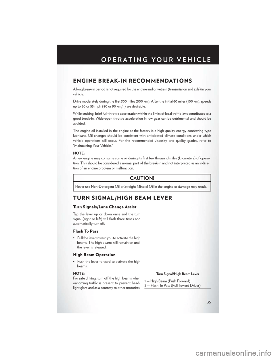
Turn Signals/Lane Change Assist
Tap the lever up or down once and the turn
signal (right or left) will flash three times and
automatically turn off.
Flash To Pass
• Pull the lever toward you to activate the highbeams. The high beams will remain on until
the lever is released.
High Beam Operation
• Push the lever forward to activate the highbeams.
NOTE:
For safe driving, turn off the high beams when
oncoming traffic is present to prevent head-
light glare and as a courtesy to other motorists.
Turn Signal/High Beam Lever
1 — High Beam (Push Forward)
2 — Flash To Pass (Pull Toward Driver)
OPERATING YOUR VEHICLE
35
Page 61 of 220
LANESENSE
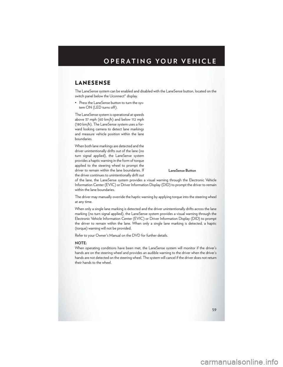
The LaneSense system can be enabled and disabled with the LaneSense button, located on the
switch panel below the Uconnect® display.
• Press the LaneSense button to turn the sys-tem ON (LED turns off ).
The LaneSense system is operational at speeds
above 37 mph (60 km/h) and below 112 mph
(180 km/h). The LaneSense system uses a for-
ward looking camera to detect lane markings
and measure vehicle position within the lane
boundaries.
When both lane markings are detected and the
driver unintentionally drifts out of the lane (no
turn signal applied), the LaneSense system
provides a haptic warning in the form of torque
applied to the steering wheel to prompt the
driver to remain within the lane boundaries. If
the driver continues to unintentionally drift out
of the lane, the LaneSense system provides a visual warning through the Electronic Vehicle
Information Center (EVIC) or Driver Information Display (DID) to prompt the driver to remain
within the lane boundaries.
The driver may manually override the haptic warning by applying torque into the steering wheel
at any time.
When only a single lane marking is detected and the driver unintentionally drifts across the lane
marking (no turn signal applied), the LaneSense system provides a visual warning through the
Electronic Vehicle Information Center (EVIC) or Driver Information Display (DID) to prompt
the driver to remain within the lane. When only a single lane marking is detected, a haptic
(torque) warning will not be provided.
Refer to your Owner's Manual on the DVD for further details.
NOTE:
When operating conditions have been met, the LaneSense system will monitor if the driver’s
hands are on the steering wheel and provides an audible warning to the driver when the driver’s
hands are not detected on the steering wheel. The system will cancel if the driver does not return
their hands to the wheel.
LaneSense Button
OPERATING YOUR VEHICLE
59
Page 76 of 220
Selling Your Vehicle
When you sell your vehicle, we recommend that you remove your Uconnect® Access Account
information from the vehicle. You can do this using the radio touchscreen in the vehicle or on the
Mopar Owner Connect website (moparownerconnect.com). Removing your account informa-
tion cancels your subscription and makes your vehicle factory-ready for a new owner/subscriber.
1. From your vehicle’s radio touchscreen, select “Uconnect® Store” from the Apps Menu.
2. Select “My Apps,” then “Settings.” Press “Remove Uconnect® Account.”
3. Enter your Uconnect® Security PIN, and select “Continue.”
For additional information on Uconnect®:
• U.S. residents - visit DriveUconnect.com or call 1-877-855-8400.
• Canadian Residents - visit DriveUconnect.ca or call, 1-800-465-2001 (English) or1-800-387-9983 (French).
Built-In Features (Uconnect® 8.4AN Only)
CAUTION!
• Ignoring the rearview mirror light could mean you may not have 9-1-1 Call service if needed. If the rearview mirror light is illuminated, have an authorized dealer service the
9-1-1 Call system immediately.
• The Occupant Restraint Controller (ORC) turns on the Air Bag Warning Light on the
instrument panel if a malfunction is detected in any part of the air bag system. If the Air
Bag Warning Light is illuminated, the air bag system may not be working properly and the
9-1-1 system may not be able to send a signal to a 9-1-1 operator. If the Air Bag Warning
Light is illuminated, have an authorized dealer service your vehicle immediately.
• If anyone in the vehicle could be in danger (e.g., fire or smoke is visible, dangerous road
conditions or location), do not wait for voice contact from a 9-1-1 operator. All occupants
should exit the vehicle immediately and move to a safe location.
• Do not add any aftermarket electrical equipment to the vehicle’s electrical system. This
may prevent your vehicle from sending a signal to initiate an emergency call. To avoid
interference that can cause the 9-1-1 Call system to fail, never add aftermarket equipment
(e.g., two-way mobile radio, CB radio, data recorder, etc.) to your vehicle’s electrical
system or modify the antennas on your vehicle. IF YOUR VEHICLE LOSES BATTERY
POWER FOR ANY REASON (INCLUDING DURING OR AFTER AN ACCI-
DENT), THE UCONNECT® FEATURES, APPS AND SERVICES, AMONG OTH-
ERS, WILL NOT OPERATE.
ELECTRONICS
74
Page 78 of 220
4.Yelp® — Customers have the ability to search for nearby destinations or a point of interest
(POI) either by category or custom search by using keywords (for example, “Italian restau-
rant”). Searching can be done by either voice or by using the touchscreen keypad. Using the
touchscreen, launch Yelp® by selecting the “Apps” icon, press the “All Apps” tab, and then
press “Yelp.” Using voice recognition, press the Voice Command (VR) button on the steering
wheel and say “Launch Yelp®.”
5. Security Alarm Notification — The Security Alarm Notification feature notifies you via email
or text (SMS) message when the vehicle’s factory-installed security alarm system has been
set-off. There are a number of reasons why your alarm may have been triggered, one of which
could be that your vehicle was stolen. If so, please see the details of the Stolen Vehicle
Assistance service below. When you register, Security Alarm Notification is automatically set
to send you an email at the mail address you provide should the alarm go off. You may also opt
to have a text message sent to your mobile device.
6. Stolen Vehicle Assistance — If your vehicle is stolen, contact local law enforcement imme-
diately to file a stolen vehicle report. Once this report has been filed, Uconnect® care can help
locate your vehicle. The Uconnect® Care agent will ask for the stolen vehicle report number
issued by local law enforcement. Then, using GPS technology and the built-in wireless
connection within your vehicle, the Uconnect® Care agent will be able to locate the stolen
vehicle and work with law enforcement to help recover it. (Vehicle must be within the United
States, have network coverage and must be registered with Uconnect® Access with an active
subscription that includes the applicable feature).
7. WiFi Hotspot — WiFi Hotspot is on-demand WiFi 3G connectivity that's built-in and ready
to go whenever you are. Once your vehicle is registered for Uconnect® Access, you can
purchase a Wifi Hotspot subscription at the Uconnect® Store. After you've made your
purchase, turn on your signal and connect your passengers devices. It's never been easier to
bring your home or office with you.
NOTE:
Your vehicle must have a working electrical system for any of the in vehicle Uconnect® features to
operate.
ELECTRONICS
76
Page 82 of 220
Launch the Uconnect® Access App on your smartphone, and login with your username and
password that was set up during registration, (this is your moparownerconnect.com login).
Accept the Terms and Conditions.
• Ensure that Via Mobile data has beenturned on under “Settings” in the Uconnect®
Access App.
• A green indicator next to the words Via Mobile will show when it is ready to provide
data to the radio (a blue indicator when data
is being sent). A red indicator means that it is
not ready to provide data.
• On android phones, an orange/yellow indi- cator signals the phone is connected to the
appropriate servers however, Bluetooth® is
turned off on their mobile phone.
Via Mobile Data Enabled
ELECTRONICS
80
Page 151 of 220
Before You Begin Programming HomeLink®
Ensure that your vehicle is parked outside of the garage before you begin programming.
For efficient programming and accurate transmission of the radio-frequency signal, it is recom-
mended that a new battery be placed in the hand-held transmitter of the device that is being
programmed to the HomeLink® system.
To erase the channels, place the ignition switch into the ON/RUN position, then push and hold the
two outside HomeLink® buttons (I and III) for up to 20 seconds or until the red indicator flashes.
NOTE:
Erasing all channels should only be performed when programming HomeLink® for the first time.
Do not erase channels when programming additional buttons.
If you have any problems, or require assistance, please call toll-free 1-800-355-3515 or, on the
Internet at for information or assistance.
Programming A Rolling Code
NOTE:
For programming Garage Door Openers that were manufactured after 1995. These Garage
Door Openers can be identified by the “LEARN” or “TRAIN” button located where the hanging
antenna is attached to the Garage Door Opener. It is NOT the button that is normally used to
open and close the door. The name and color of the button may vary by manufacturer.
1. Place the ignition switch into the ON/RUN position.
2. Place the hand-held transmitter 1 to 3 inches (3 to 8 cm) away from the HomeLink® button youwish to program while keeping the HomeLink® indicator light in view.
3. Push and hold the HomeLink® button you want to program while you push and hold the hand-held transmitter button.
4.
Continue to hold both buttons and observe the indicator light. The HomeLink® indicator will flash
slowly and then rapidly after HomeLink® has received the frequency signal from the hand-held
transmitter. Release both buttons after the indicator light changes from slow to rapid.
5. At the garage door opener motor (in the garage), locate the “LEARN” or “TRAINING” button. This can usually be found where the hanging antenna wire is attached to the garage
door opener motor. Firmly push and release the “LEARN” or “TRAINING” button.
NOTE:
You have 30 seconds in which to initiate the next step after the LEARN button has been pushed.
6. Return to the vehicle and push the programmed HomeLink® button twice (holding the button for two seconds each time). If the device is plugged in and activates, programming is
complete.
ELECTRONICS
149