light CHRYSLER 200 CONVERTIBLE 2012 1.G User Guide
[x] Cancel search | Manufacturer: CHRYSLER, Model Year: 2012, Model line: 200 CONVERTIBLE, Model: CHRYSLER 200 CONVERTIBLE 2012 1.GPages: 108, PDF Size: 2.83 MB
Page 3 of 108
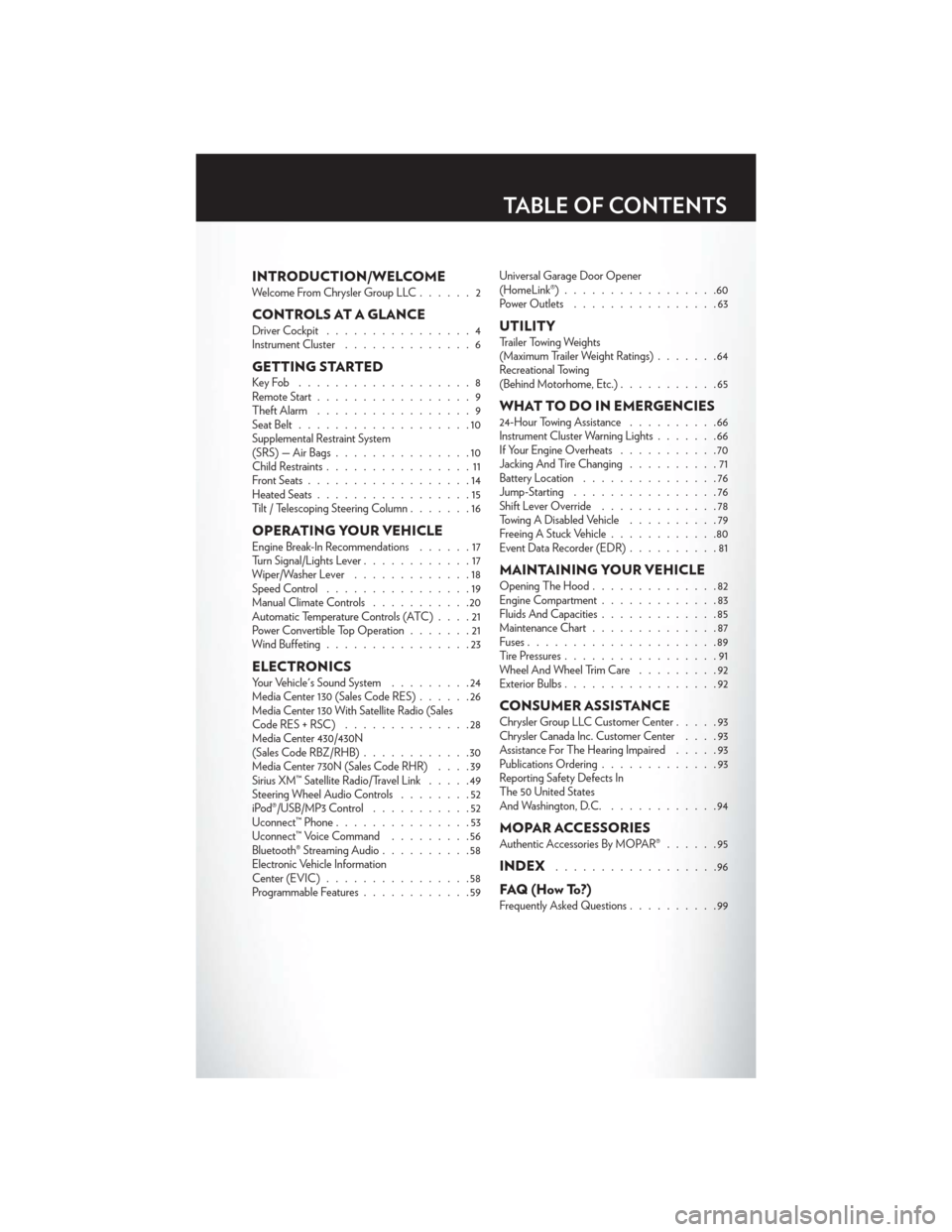
INTRODUCTION/WELCOMEWelcome From Chrysler Group LLC......2
CONTROLS AT A GLANCEDriver Cockpit................4
Instrument Cluster ..............6
GETTING STARTEDKeyFob ...................8
Remote Start.................9
Theft Alarm .................9
Seat Belt ...................10
Supplemental Restraint System
(SRS) — Air Bags ...............10
Child Restraints ................11
Front Seats ..................14
Heated Seats .................15
Tilt / Telescoping Steering Column .......16
OPERATING YOUR VEHICLEEngine Break-In Recommendations ......17
Turn Signal/Lights Lever ............17
Wiper/Washer Lever .............18
Speed Control ................19
Manual Climate Controls ...........20
Automatic Temperature Controls (ATC) ....21
Power Convertible Top Operation .......21
Wind Buffeting ................23
ELECTRONICSYour Vehicle's Sound System .........24
Media Center 130 (Sales Code RES) ......26
Media Center 130 With Satellite Radio (Sales
CodeRES+RSC) ..............28
Media Center 430/430N
(Sales Code RBZ/RHB) ............30
Media Center 730N (Sales Code RHR) ....39
Sirius XM™ Satellite Radio/Travel Link .....49
Steering Wheel Audio Controls ........52
iPod®/USB/MP3 Control ...........52
Uconnect™ Phone ...............53
Uconnect™ Voice Command .........56
Bluetooth® Streaming Audio ..........58
Electronic Vehicle Information
Center (EVIC) ................58
Programmable Features ............59 Universal Garage Door Opener
(HomeLink®)
.................60
Power Outlets ................63
UTILITYTrailer Towing Weights
(Maximum Trailer Weight Ratings) .......64
Recreational Towing
(Behind Motorhome, Etc.) ...........65
WHAT TO DO IN EMERGENCIES24-Hour Towing Assistance ..........66
Instrument Cluster Warning Lights .......66
If Your Engine Overheats ...........70
Jacking And Tire Changing ..........71
Battery Location ...............76
Jump-Starting ................76
Shift Lever Override .............78
Towing A Disabled Vehicle ..........79
Freeing A Stuck Vehicle ............80
Event Data Recorder (EDR) ..........81
MAINTAINING YOUR VEHICLEOpening The Hood..............82
Engine Compartment .............83
Fluids And Capacities .............85
Maintenance Chart ..............87
Fuses .....................89
Tire Pressures .................91
Wheel And Wheel Trim Care .........92
Exterior Bulbs .................92
CONSUMER ASSISTANCEChrysler Group LLC Customer Center .....93
Chrysler Canada Inc. Customer Center ....93
Assistance For The Hearing Impaired .....93
Publications Ordering .............93
Reporting Safety Defects In
The 50 United States
And Washington, D.C. ............94
MOPAR ACCESSORIESAuthentic Accessories By MOPAR® ......95
INDEX..................96
FAQ(HowTo?)Frequently Asked Questions..........99
TABLE OF CONTENTS
Page 7 of 108
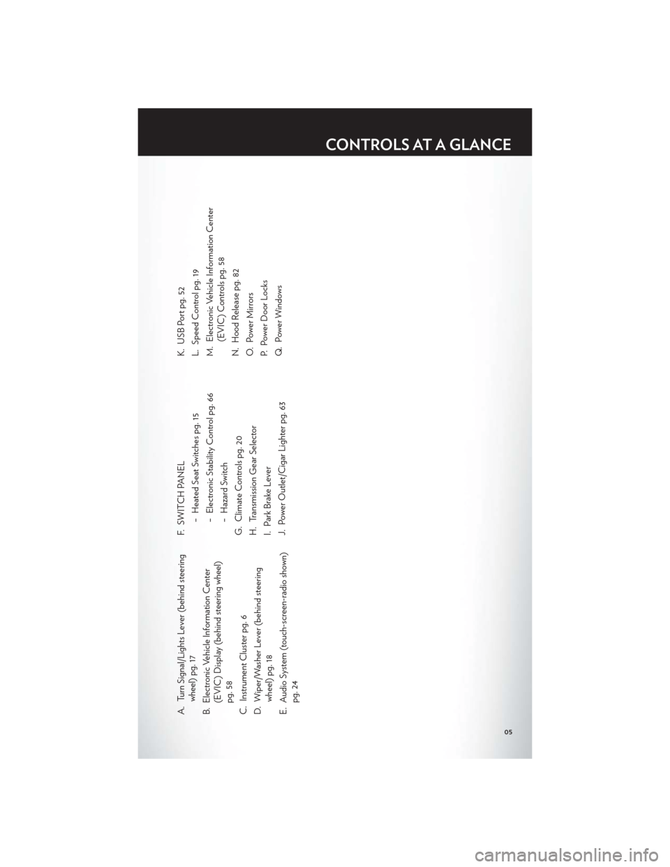
A. Turn Signal/Lights Lever (behind steeringwheel) pg. 17
B. Electronic Vehicle Information Center (EVIC) Display (behind steering wheel)
pg. 58
C. Instrument Cluster pg. 6
D. Wiper/Washer Lever (behind steering wheel) pg. 18
E. Audio System (touch-screen-radio shown) pg. 24 F. SWITCH PANEL
− Heated Seat Switches pg. 15
− Electronic Stability Control pg. 66
− Hazard Switch
G. Climate Controls pg. 20
H. Transmission Gear Selector
I. Park Brake Lever
J. Power Outlet/Cigar Lighter pg. 63 K. USB Port pg. 52
L. Speed Control pg. 19
M. Electronic Vehicle Information Center
(EVIC) Controls pg. 58
N. Hood Release pg. 82
O. Power Mirrors
P. Power Door Locks
Q. Power Windows
CONTROLS AT A GLANCE
05
Page 8 of 108
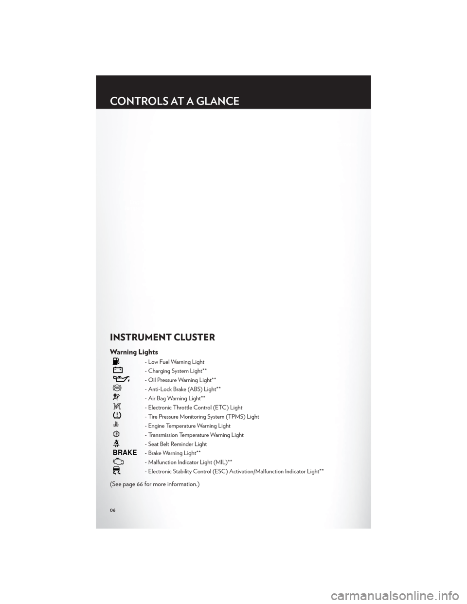
INSTRUMENT CLUSTER
Warning Lights
- Low Fuel Warning Light
- Charging System Light**
- Oil Pressure Warning Light**
- Anti-Lock Brake (ABS) Light**
- Air Bag Warning Light**
- Electronic Throttle Control (ETC) Light
- Tire Pressure Monitoring System (TPMS) Light
- Engine Temperature Warning Light
- Transmission Temperature Warning Light
- Seat Belt Reminder Light
BRAKE- Brake Warning Light**
- Malfunction Indicator Light (MIL)**
- Electronic Stability Control (ESC) Activation/Malfunction Indicator Light**
(See page 66 for more information.)
CONTROLS AT A GLANCE
06
Page 9 of 108
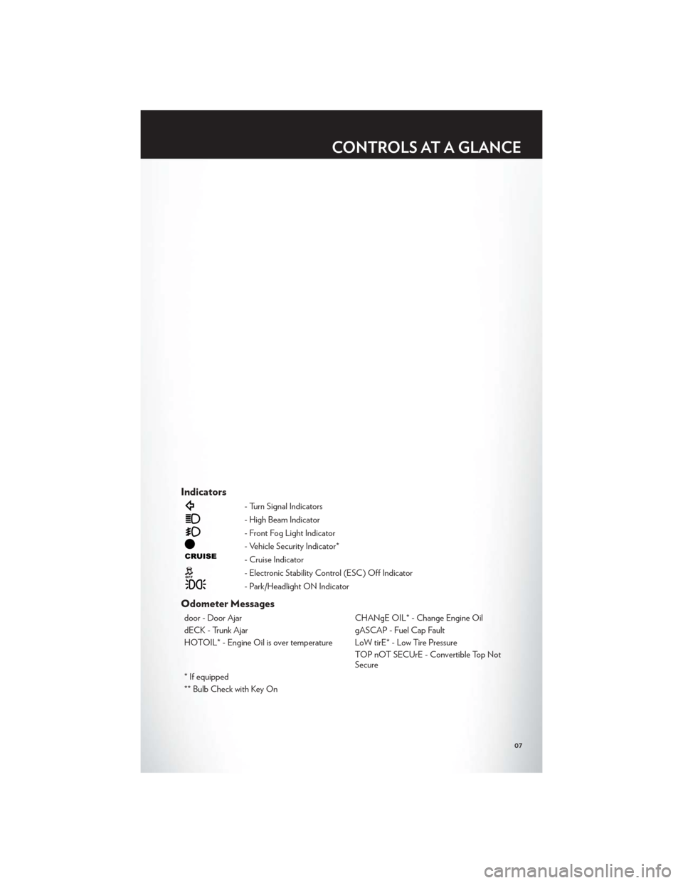
Indicators
- Turn Signal Indicators
- High Beam Indicator
- Front Fog Light Indicator
- Vehicle Security Indicator*
- Cruise Indicator
- Electronic Stability Control (ESC) Off Indicator
- Park/Headlight ON Indicator
Odometer Messages
door - Door AjarCHANgE OIL* - Change Engine Oil
dECK - Trunk Ajar gASCAP - Fuel Cap Fault
HOTOIL* - Engine Oil is over temperature LoW tirE* - Low Tire Pressure TOP nOT SECUrE - Convertible Top Not
Secure
* If equipped
** Bulb Check with Key On
CONTROLS AT A GLANCE
07
Page 12 of 108
SEAT BELT
• Be sure everyone in your vehicle is in a seat and using a seat belt properly.
• Position the lap belt across your thighs, below your abdomen. To remove slack in the lapportion, pull up a bit on the shoulder belt. To loosen the lap belt if it is too tight, tilt the
latch plate and pull on the lap belt. A snug belt reduces the risk of sliding under the belt in
a collision.
• Position the shoulder belt on your chest so that it is comfortable and not resting on your neck. The retractor will withdraw any slack in the belt.
• A shoulder belt placed behind you will not protect you from injury during a collision. You are more likely to hit your head in a collision if you do not wear your shoulder belt. The
lap and shoulder belt are meant to be used together.
• A belt that is too loose will not protect you properly. In a sudden stop you could move too far forward, increasing the possibility of injury. Wear your seat belt snugly.
• A frayed or torn belt could rip apart in a collision and leave you with no protection. Inspect the belt system periodically, checking for cuts, frays, or loose parts. Damaged
parts must be replaced immediately. Do not disassemble or modify the system. Seat belt
assemblies must be replaced after a collision if they have been damaged (bent retractor,
torn webbing, etc.).
• The seat belts for both front seating positions are equipped with pretensioning devices that are designed to remove slack from the seat belt in the event of a collision.
• A deployed pretensioner or a deployed air bag must be replaced immediately.
WARNING!
In a collision, you and your passengers can suffer much greater injuries if you are not
buckled up properly. You can strike the interior of your vehicle or other passengers, or you
can be thrown out of the vehicle. Always be sure you and others in your vehicle are buckled
up properly.
SUPPLEMENTAL RESTRAINT SYSTEM (SRS) — AIR
BAGS
• This vehicle has Advanced Front Air Bags for both the driver and right front passenger as a supplement to the seat belt restraint system. The Advanced Front Air Bags will not
deploy in every type of collision.
• Advanced Front Air Bags are designed to provide additional protection by supplementing the seat belts in certain frontal collisions depending on the severity and type of collision.
Advanced Front Air Bags are not expected to reduce the risk of injury in rear, side, or
rollover collisions.
• This vehicle is equipped with Supplemental Seat-Mounted Side Air Bags to provide enhanced protection to help protect an occupant during a side impact.
• If the Air Bag Warning Light
is not on during starting, stays on, or turns on while
driving, have the vehicle serviced by an authorized service center immediately.
GETTING STARTED
10
Page 19 of 108
ENGINE BREAK-IN RECOMMENDATIONS
• A long break-in period is not required for the engine and drivetrain (transmission andaxle) in your vehicle.
• Drive moderately during the first 300 miles (500 km). After the initial 60 miles (100 km), speeds up to 50 or 55 mph (80 or 90 km/h) are desirable.
• While cruising, brief full-throttle acceleration within the limits of local traffic laws contributes to a good break-in. Wide-open throttle acceleration in low gear can be
detrimental and should be avoided.
• The engine oil installed in the engine at the factory is a high-quality energy conserving type lubricant. Oil changes should be consistent with anticipated climate conditions under
which vehicle operations will occur. For the recommended viscosity and quality grades,
refer to “Maintaining Your Vehicle”.
NOTE:A new engine may consume some oil during its first few thousand miles (kilometers)
of operation. This should be considered a normal part of the break-in and not interpreted as an
indication of difficulty.
CAUTION!
Never use Non-Detergent Oil or Straight Mineral Oil in the engine or damage may result.
TURN SIGNAL/LIGHTS LEVER
Headlights/Parking Lights/Automatic Headlights
• Rotate the end of the lever to the first detent for parking lights, the second
detent for headlights
and the third detent for AUTO.
• When set to AUTO, the system automatically turns the headlights on or off based on ambient light levels.
OPERATING YOUR VEHICLE
17
Page 20 of 108
Instrument Panel Dimmer
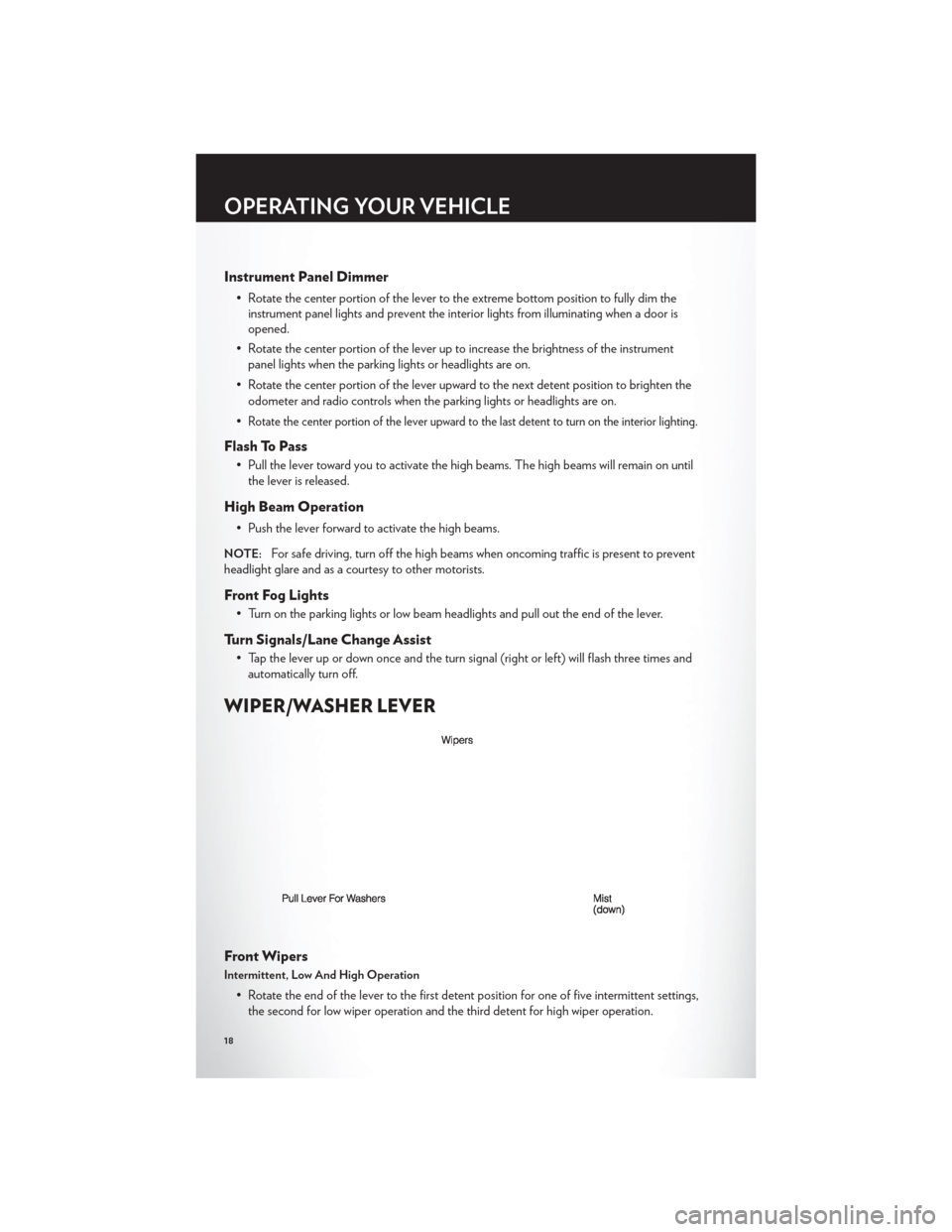
• Rotate the center portion of the lever to the extreme bottom position to fully dim theinstrument panel lights and prevent the interior lights from illuminating when a door is
opened.
• Rotate the center portion of the lever up to increase the brightness of the instrument panel lights when the parking lights or headlights are on.
• Rotate the center portion of the lever upward to the next detent position to brighten the odometer and radio controls when the parking lights or headlights are on.
•
Rotate the center portion of the lever upward to the last detent to turn on the interior lighting.
Flash To Pass
• Pull the lever toward you to activate the high beams. The high beams will remain on until the lever is released.
High Beam Operation
• Push the lever forward to activate the high beams.
NOTE:For safe driving, turn off the high beams when oncoming traffic is present to prevent
headlight glare and as a courtesy to other motorists.
Front Fog Lights
• Turn on the parking lights or low beam headlights and pull out the end of the lever.
Turn Signals/Lane Change Assist
• Tap the lever up or down once and the turn signal (right or left) will flash three times and automatically turn off.
WIPER/WASHER LEVER
Front Wipers
Intermittent, Low And High Operation
• Rotate the end of the lever to the first detent position for one of five intermittent settings,the second for low wiper operation and the third detent for high wiper operation.
OPERATING YOUR VEHICLE
18
Page 23 of 108

AUTOMATIC TEMPERATURE CONTROLS (ATC)
Automatic Operation
• Turn the Mode and Blower Controls to the AUTO position.
• Select the desired temperature by rotating the Temperature Control.
• The system will maintain the set temperature automatically.
Air Conditioning
• If the air conditioning button is pressed while in the AUTO mode, the indicator light mayflash three times to indicate the cabin air is being controlled automatically.
Air Recirculation
• Use recirculation for maximum A/C operation.
• For window defogging, turn the air recirculation button off.
• If the recirculation button is pressed while in the AUTO mode, the indicator light mayflash three times to indicate the cabin air is being controlled automatically.
Heated Mirrors
• The mirrors are heated to melt frost or ice. This feature is activated whenever you turn onthe rear window defroster.
POWER CONVERTIBLE TOP OPERATION
• Before lowering the top, verify the cargo shield is perfectly positioned in the trunk.
Positioning The Cargo Shield For Top Operation
• Pull the cargo shield toward you to begin unfolding the panels. Grasp the handle in thecenter of the outermost (top) panel and raise the cargo shield. Then, align and seat the
tabs at each end of the cargo shield in the V slots in the trunk liner as shown in the
illustration.
OPERATING YOUR VEHICLE
21
Page 61 of 108
PROGRAMMABLE FEATURES
Electronic Vehicle Information Center (EVIC)
• The EVIC can be used to program the following Personal Settings. Press and release theMENU button until Personal Settings displays, then press the DOWN
button to
scroll through the settings. Press the SELECT
button to change the setting.
• Language • Key Off Power Delay
• Auto Unlock On Exit • Illuminated Approach
• RKE Unlock • Hill Start Assist (HSA)
• Sound Horn With Lock • Display Units In
• Flash Lamps With Lock • Calibrate Compass
• Headlamp Off Delay • Compass Variance
• Headlights With Wipers (Available with
Auto Headlights Only)
Key Fob Programmable Features
• The following features may also be programmed by using the Key Fob transmitter or the ignition switch and driver's door lock switch.
NOTE:Pressing the LOCK button while you are inside the vehicle will activate the Vehicle
Security Alarm. Opening a door with the Vehicle Security Alarm activated will cause the alarm
to sound. Press the UNLOCK button to deactivate the Vehicle Security Alarm.
Unlock On First Press
• To unlock either the driver's side, or all doors, on the first press of the UNLOCK button:
• Press and hold the LOCK button for at least 4 seconds, but no longer than 10 seconds. Then, press and hold the UNLOCK button while still holding the LOCK button.
• Release both buttons at the same time.
Auto Unlock Doors On Exit
• To have all of the vehicle doors unlock when any door is opened: • Enter your vehicle and close all the doors.
• Cycle the ignition switch between LOCK and ON and then back to LOCK four times, ending up in the LOCK position (do not start the engine).
• Press the power door UNLOCK switch to unlock the doors. A single chime will indicate that programming is complete.
Sound Horn With Lock
• To turn the horn chirp on or off when the doors are locked:
• Press the LOCK button for at least 4 seconds, but no longer than 10 seconds. Then, press the PANIC button while still holding the LOCK button.
• Release both buttons at the same time.
ELECTRONICS
59
Page 62 of 108
Flashing Lights With Lock
• The turn signal lights flashing, when the doors are locked or unlocked, feature can beturned on or off. To turn this feature on or off:
• Press and hold the UNLOCK button for at least 4 seconds, but no longer than 10 seconds. Then, press and hold the LOCK button while still holding the UNLOCK
button.
• Release both buttons at the same time.
UNIVERSAL GARAGE DOOR OPENER (HomeLink®)
• HomeLink® replaces up to three hand-held transmitters that operate devices such as garage door openers, motorized gates, lighting or home security systems. The
HomeLink® unit is powered by your vehicles 12 Volt battery.
• The HomeLink® buttons that are located in the overhead console or sunvisor designate the three different HomeLink® channels.
• The HomeLink® indicator is located above the center button.
Before You Begin Programming HomeLink®
• Be sure that your vehicle is parked outside of the garage before you begin programming.
• For more efficient programming and accurate transmission of the radio-frequency signal it is recommended that a new battery be placed in the hand-held transmitter of the device
that is being programmed to the HomeLink® system.
• Erase all channels before you begin programming. To erase the channels, place the ignition switch into the ON/RUN position, then press and hold the two outside
HomeLink® buttons (I and III) for up 20 seconds or until the red indicator flashes.
NOTE:
• Erasing all channels should only be performed when programming HomeLink® for the firsttime. Do not erase channels when programming additional buttons.
• If you have any problems, or require assistance, please call toll-free 1–800–355–3515 or, on the Internet at www.HomeLink.com for information or assistance.
ELECTRONICS
60