change wheel CHRYSLER 200 CONVERTIBLE 2014 1.G Owners Manual
[x] Cancel search | Manufacturer: CHRYSLER, Model Year: 2014, Model line: 200 CONVERTIBLE, Model: CHRYSLER 200 CONVERTIBLE 2014 1.GPages: 522, PDF Size: 3.09 MB
Page 236 of 522
RESET Button
To reset the display shown, turn the ignition switch to the
ON position, then press and hold the RESET button
located on the steering wheel.
The following displays can be reset or changed:
•Trip A
• Trip B
Trip Odometer (ODO)
This display shows the distance traveled since the last
reset. Press and release the STEP button on the instru-
ment cluster to switch from odometer, to Trip A or Trip B. Trip A
Shows the total distance traveled for Trip A since the last
reset.
Trip B
Shows the total distance traveled for Trip B since the last
reset.
234 UNDERSTANDING YOUR INSTRUMENT PANEL
Page 283 of 522
The remote sound system controls are located on the rear
surface of the steering wheel, at the three and nine
o’clock positions.
The right-hand rocker switch has a pushbutton in the
center, and controls the volume and mode of the sound
system. Pressing the top of the rocker switch will increase
the volume. Pressing the bottom of the rocker switch will
decrease the volume. Pressing the center button changes
the operation of the radio from AM to FM, or to CD
mode, depending on which radio is in the vehicle.
The left-hand rocker switch has a pushbutton in the
center. The function of the left-hand switch is different,
depending on which mode you are in.
The following describes the left-hand rocker switch op-
eration in each mode.Radio Operation
Pressing the top of the switch will SEEK up for the next
listenable station, and pressing the bottom of the switch
will SEEK down for the next listenable station.
The button located in the center of the left-hand switch
will tune to the next preset station that you have pro-
grammed in the radio preset pushbutton.
CD Player
Pressing the top of the switch once will go to the next
track on the CD. Pressing the bottom of the switch once
will go to the beginning of the current track, or to the
beginning of the previous track if it is within one second
after the current track begins to play.
If you press the switch up or down twice it plays the
second track; three times, it will play the third, etc.
The button in the center of the left-hand switch has no
function in this mode.
4
UNDERSTANDING YOUR INSTRUMENT PANEL 281
Page 362 of 522
WARNING!
•Do not use a tire, wheel size or rating other than
that specified for your vehicle. Some combinations
of unapproved tires and wheels may change sus-
pension dimensions and performance characteris-
tics, resulting in changes to steering, handling, and
braking of your vehicle. This can cause unpredict-
able handling and stress to steering and suspen-
sion components. You could lose control and have
a collision resulting in serious injury or death. Use
only the tire and wheel sizes with load ratings
approved for your vehicle.
• Never use a tire with a smaller load index or
capacity, other than what was originally equipped
on your vehicle. Using a tire with a smaller load
index could result in tire overloading and failure.
You could lose control and have a collision.
(Continued)
WARNING! (Continued)
•Failure to equip your vehicle with tires having
adequate speed capability can result in sudden tire
failure and loss of vehicle control.
CAUTION!
Replacing original tires with tires of a different size
may result in false speedometer and odometer read-
ings.
TIRE CHAINS (TRACTION DEVICES)
Due to limited clearance, tire chains or traction devices
are not recommended.
CAUTION!
Damage to the vehicle may result if tire chains are used.
360 STARTING AND OPERATING
Page 366 of 522
NOTE:
•The TPMS is not intended to replace normal tire care
and maintenance, or to provide warning of a tire
failure or condition.
• The TPMS should not be used as a tire pressure gauge
while adjusting your tire pressure.
• Driving on a significantly under-inflated tire causes
the tire to overheat and can lead to tire failure.
Under-inflation also reduces fuel efficiency and tire
tread life, and may affect the vehicle’s handling and
stopping ability.
• The TPMS is not a substitute for proper tire mainte-
nance, and it is the driver ’s responsibility to maintain
correct tire pressure using an accurate tire pressure
gauge, even if under-inflation has not reached the level
to trigger illumination of the “Tire Pressure Monitor-
ing Telltale Light.” •
Seasonal temperature changes will affect tire pressure,
and the TPMS will monitor the actual tire pressure in
the tire.
Base System
The Tire Pressure Monitor System (TPMS) uses wireless
technology with wheel rim mounted electronic sensors to
monitor tire pressure levels. Sensors, mounted to each
wheel as part of the valve stem, transmit tire pressure
readings to the Receiver Module.
NOTE: It is particularly important for you to check the
tire pressure in all of the tires on your vehicle monthly
and to maintain the proper pressure.
The TPMS consists of the following components:
• Receiver Module
• Four Tire Pressure Monitoring Sensors
• Tire Pressure Monitoring Telltale Light
364 STARTING AND OPERATING
Page 402 of 522
JACKING AND TIRE CHANGING
WARNING!
•Do not attempt to change a tire on the side of the
vehicle close to moving traffic. Pull far enough off
the road to avoid the danger of being hit when
operating the jack or changing the wheel.
• Being under a jacked-up vehicle is dangerous. The
vehicle could slip off the jack and fall on you. You
could be crushed. Never put any part of your body
under a vehicle that is on a jack. If you need to get
under a raised vehicle, take it to a service center
where it can be raised on a lift.
• Never start or run the engine while the vehicle is
on a jack.
(Continued)
WARNING! (Continued)
•The jack is designed to be used as a tool for
changing tires only. The jack should not be used to
lift the vehicle for service purposes. The vehicle
should be jacked on a firm level surface only.
Avoid ice or slippery areas.
Jack Location
The jack and jack-handle are stowed under the load floor
in the trunk.
Spare Tire Stowage
The compact spare tire is stowed under the rear load floor
in the trunk.
400 WHAT TO DO IN EMERGENCIES
Page 403 of 522
Spare Tire Removal
Lift up the load floor cover and remove the hold down.
Preparations For Jacking
1. Park the vehicle on a firm, level surface. Avoid ice orslippery areas.
WARNING!
Do not attempt to change a tire on the side of the
vehicle close to moving traffic, pull far enough off
the road to avoid the danger of being hit when
operating the jack or changing the wheel.
2. Turn on the Hazard Warning flashers.
3. Set the parking brake.
4. Place the shift lever into PARK (automatic transmis- sion) or REVERSE (manual transmission).
5. Turn OFF the ignition.
Spare Tire And Jack Storage
6
WHAT TO DO IN EMERGENCIES 401
Page 405 of 522
WARNING!(Continued)
•Only use the jack in the positions indicated and for
lifting this vehicle during a tire change.
• If working on or near a roadway, be extremely
careful of motor traffic.
• To assure that spare tires, flat or inflated, are
securely stowed, spares must be stowed with the
valve stem facing the ground.
CAUTION!
Do not attempt to raise the vehicle by jacking on
locations other than those indicated in the Jacking
Instructions for this vehicle.
NOTE: Refer to the Compact Spare Tire section of Tires--
General Information--for information about the spare
tire, its use, and operation.
1. Remove the scissors jack and lug wrench from the spare wheel as an assembly. Turn the jack screw to the
left to loosen the lug wrench, and remove the wrench
from the jack assembly.
NOTE: The jack handle attaches to the side of the jack
with two attachment points. When the jack is partially
expanded, the tension between the two attachment
points holds the jack handle in place.
Jack Warning Label
6
WHAT TO DO IN EMERGENCIES 403
Page 407 of 522
4. Turn the jack screw to the left until the jack can beplaced under the jacking location. Once the jack is
positioned, turn the jack screw to the right until the
jack head is properly engaged to the jacking location
on the wheel to be changed. Do not raise the vehicle
until you are sure the jack is securely engaged.
Rear Jacking LocationJack Engaged (Front Jacking Location)6
WHAT TO DO IN EMERGENCIES 405
Page 473 of 522
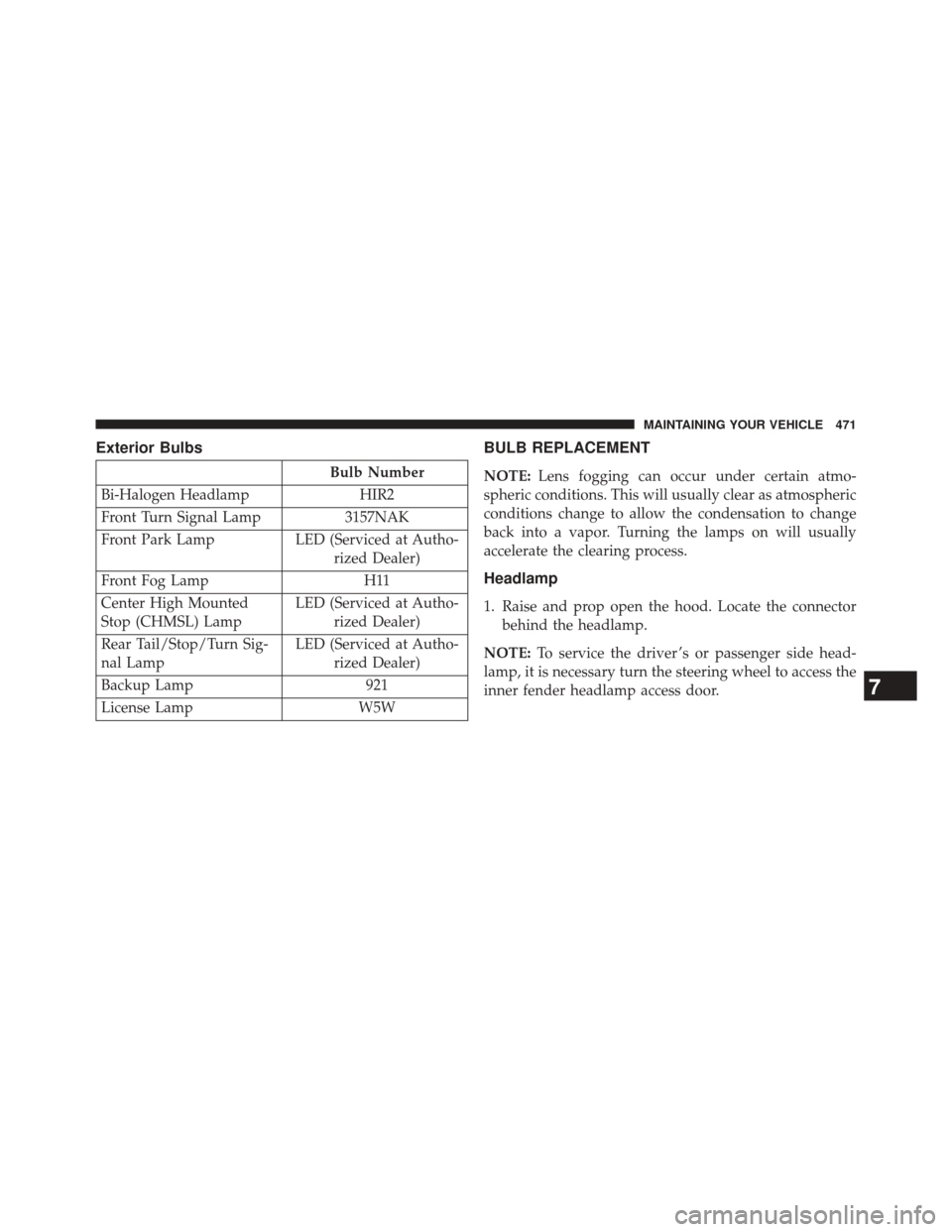
Exterior Bulbs
Bulb Number
Bi-Halogen Headlamp HIR2
Front Turn Signal Lamp 3157NAK
Front Park Lamp LED (Serviced at Autho-
rized Dealer)
Front Fog Lamp H11
Center High Mounted
Stop (CHMSL) Lamp LED (Serviced at Autho-
rized Dealer)
Rear Tail/Stop/Turn Sig-
nal Lamp LED (Serviced at Autho-
rized Dealer)
Backup Lamp 921
License Lamp W5W
BULB REPLACEMENT
NOTE:Lens fogging can occur under certain atmo-
spheric conditions. This will usually clear as atmospheric
conditions change to allow the condensation to change
back into a vapor. Turning the lamps on will usually
accelerate the clearing process.
Headlamp
1. Raise and prop open the hood. Locate the connector behind the headlamp.
NOTE: To service the driver ’s or passenger side head-
lamp, it is necessary turn the steering wheel to access the
inner fender headlamp access door.
7
MAINTAINING YOUR VEHICLE 471