wheel CHRYSLER 200 CONVERTIBLE 2014 1.G Owner's Manual
[x] Cancel search | Manufacturer: CHRYSLER, Model Year: 2014, Model line: 200 CONVERTIBLE, Model: CHRYSLER 200 CONVERTIBLE 2014 1.GPages: 124, PDF Size: 3.31 MB
Page 80 of 124

•IF THE LIGHT STARTS FLASHING INDICATING A LOW TIRE PRESSURE, AD-
JUST THE AIR PRESSURE IN THE LOW TIRE TO THE AIR PRESSURE SHOWN
ON THE VEHICLE PLACARD OR TIRE INFLATION PRESSURE LABEL LO-
CATED ON THE DRIVER'S DOOR.
NOTE:
AFTER INFLATION, THE VEHICLE MAY NEED TO BE DRIVEN FOR 20 MINUTES
BEFORE THE FLASHING LIGHT WILL TURN OFF.
• Please note that the TPMS is not a substitute for proper tire maintenance, and it is the driver’s responsibility to maintain correct tire pressure, even if under-inflation has not reached the level
to trigger illumination of the TPMS low tire pressure telltale.
• Your vehicle has also been equipped with a TPMS malfunction indicator to indicate when the system is not operating properly. The TPMS malfunction indicator is combined with the low
tire pressure telltale. When the system detects a malfunction, the telltale will flash for
approximately one minute and then remain continuously illuminated. This sequence will
continue each time the vehicle is restarted as long as the malfunction exists.
• When the malfunction indicator is illuminated, the system may not be able to detect or signal low tire pressure as intended. TPMS malfunctions may occur for a variety of reasons, including
the installation of replacement or alternate tires or wheels on the vehicle that prevent the
TPMS from functioning properly. Always check the TPMS malfunction telltale after replacing
one or more tires or wheels on your vehicle, to ensure that the replacement or alternate tires
and wheels allow the TPMS to continue to function properly.
NOTE:
Tire pressures change by approximately 1 psi (7 kPa) per 12° F (7° C) of air temperature change.
Keep this in mind when checking tire pressure inside a garage, especially in the Winter. Example:
If garage temperature is 68°F (20°C) and the outside temperature is 32°F (0°C), then the cold
tire inflation pressure should be increased by 3 psi (21 kPa), which equals 1 psi (7 kPa) for every
12°F (7°C) for this outside temperature condition.
CAUTION!
The TPMS has been optimized for the original equipment tires and wheels. TPMS pressures
and warning have been established for the tire size equipped on your vehicle. Undesirable
system operation or sensor damage may result when using replacement equipment that is not
of the same size, type, and/or style. Aftermarket wheels can cause sensor damage. Do not use
tire sealant from a can, or balance beads if your vehicle is equipped with a TPMS, as damage
to the sensors may result.
WHAT TO DO IN EMERGENCIES
78
Page 85 of 124

6. Block both the front and rear of the wheel diagonally opposite the jacking position. Forexample, if changing the right front tire, block the left rear wheel.
NOTE:
Passengers should not remain in the vehicle
while the vehicle is being jacked.
Jacking Instructions
1. Remove the scissors jack and lug wrench from the spare wheel as an assembly. Turn
the jack screw to the left to loosen the lug
wrench, and remove the wrench from the
jack assembly.
NOTE:
The jack handle attaches to the side of the jack with two attachment points. When the jack is
partially expanded, the tension between the two attachment points holds the jack handle in place.
2. Loosen, but do not remove, the wheel nuts by turning them to the left one turn while
the wheel is still on the ground.
WHAT TO DO IN EMERGENCIES
83
Page 86 of 124
3. There is a front and rear jacking location on each side of the vehicle.
4. Turn the jack screw to the left until the jack can be placed under the jacking location. Once thejack is positioned, turn the jack screw to the right until the jack head is properly engaged with
the lift area closest to the wheel to be changed. Do not raise the vehicle until you are sure the
jack is securely engaged.
5. Raise the vehicle by turning the jack screw to the right, using the swivel wrench. Raise the vehicle only until the tire just clears the surface and enough clearance is obtained to install the
spare tire. Minimum tire lift provides maximum stability.
6. Remove the wheel nuts, and pull the wheel and wheel covers (where applicable) off the hub. Install the spare wheel and wheel nuts with the cone shaped end of the nuts toward the wheel.
Lightly tighten the nuts.
7. Lower the vehicle by turning the jack screw to the left.
8. Finish tightening the nuts. Push down on the wrench while at the end of the handle for
increased leverage. Tighten the lug nuts in a
star pattern until each nut has been tight-
ened twice. The correct wheel nut torque is
100 ft lbs (135 N·m). If you doubt that you
have tightened the nuts correctly, have
them checked with a torque wrench by your
authorized dealer or at a service station.
9. Remove the wheel blocks and lower the jack until it is free. Reassemble the lug wrench to the jack assembly and stow it in the spare tire area. Secure the assembly using the means provided.
10. Place the deflated (flat) tire in the cargo area and have the tire repaired or replaced as soon
as possible.
11. Check the tire pressure as soon as possible. Correct the tire pressure as required.
WHAT TO DO IN EMERGENCIES
84
Page 87 of 124
Road Tire Installation
Vehicles Equipped With Wheel Covers
1. Mount the road tire on the axle.
2. To ease the installation process for steel wheels with wheel covers, install two lug nuts on themounting studs which are on each side of the valve stem. Install the lug nuts with the cone
shaped end of the nut toward the wheel. Lightly tighten the lug nuts.
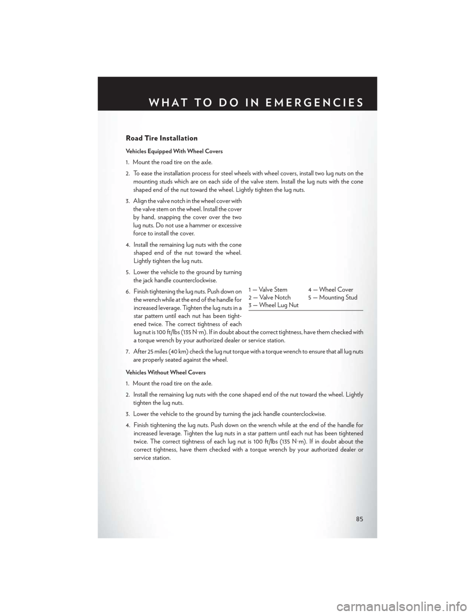
3. Align the valve notch in the wheel cover with the valve stem on the wheel. Install the cover
by hand, snapping the cover over the two
lug nuts. Do not use a hammer or excessive
force to install the cover.
4. Install the remaining lug nuts with the cone shaped end of the nut toward the wheel.
Lightly tighten the lug nuts.
5. Lower the vehicle to the ground by turning the jack handle counterclockwise.
6. Finish tightening the lug nuts. Push down on the wrench while at the end of the handle for
increased leverage. Tighten the lug nuts in a
star pattern until each nut has been tight-
ened twice. The correct tightness of each
lug nut is 100 ft/lbs (135 N·m). If in doubt about the correct tightness, have them checked with
a torque wrench by your authorized dealer or service station.
7. After 25 miles (40 km) check the lug nut torque with a torque wrench to ensure that all lug nuts are properly seated against the wheel.
Vehicles Without Wheel Covers
1. Mount the road tire on the axle.
2. Install the remaining lug nuts with the cone shaped end of the nut toward the wheel. Lightly tighten the lug nuts.
3. Lower the vehicle to the ground by turning the jack handle counterclockwise.
4. Finish tightening the lug nuts. Push down on the wrench while at the end of the handle for increased leverage. Tighten the lug nuts in a star pattern until each nut has been tightened
twice. The correct tightness of each lug nut is 100 ft/lbs (135 N·m). If in doubt about the
correct tightness, have them checked with a torque wrench by your authorized dealer or
service station.
1 — Valve Stem 4 — Wheel Cover
2 — Valve Notch 5 — Mounting Stud
3 — Wheel Lug Nut
WHAT TO DO IN EMERGENCIES
85
Page 88 of 124
5. After 25 miles (40 km) check the lug nut torque with a torque wrench to ensure that all lug nutsare properly seated against the wheel.
CAUTION!
• Do not attempt to raise the vehicle by jacking on locations other than those indicated in the Jacking Instructions for this vehicle.
• Be sure to mount the spare tire with the valve stem facing outward. The vehicle could be
damaged if the spare tire is mounted incorrectly.
WARNING!
• Being under a jacked-up vehicle is dangerous. The vehicle could slip off the jack and fall onyou. You could be crushed. Never put any part of your body under a vehicle that is on a
jack. If you need to get under a raised vehicle, take it to a service center where it can be
raised on a lift.
• Never start or run the engine while the vehicle is on a jack.
• The jack is designed to be used as a tool for changing tires only. The jack should not be
used to lift the vehicle for service purposes. The vehicle should be jacked on a firm level
surface only. Avoid ice or slippery areas.
• Do not attempt to change a tire on the side of the vehicle close to moving traffic, pull far
enough off the road to avoid the danger of being hit when operating the jack or changing
the wheel.
• Carefully follow these tire changing warnings to help prevent personal injury or damage to
your vehicle:
• Always park on a firm, level surface as far from the edge of the roadway as possiblebefore raising the vehicle.
• Turn on the Hazard Warning flasher.
• Block the wheel diagonally opposite the wheel to be raised.
• Set the parking brake firmly and set an automatic transmission in PARK; a manual
transmission in REVERSE.
• Do not let anyone sit in the vehicle when it is on a jack.
• Do not get under the vehicle when it is on a jack.
• Only use the jack in the positions indicated and for lifting this vehicle during a tire change.
• If working on or near a roadway, be extremely careful of motor traffic.
• To assure that spare tires, flat or inflated, are securely stowed, spares must be stowed with
the valve stem facing the ground.
• Raising the vehicle higher than necessary can make the vehicle less stable. It could slip off
the jack and hurt someone near it. Raise the vehicle only enough to remove the tire.
• To avoid possible personal injury, handle the wheel covers with care to avoid contact with
any sharp edges.
• A loose tire or jack thrown forward in a collision or hard stop could injure the occupants in
the vehicle. Have the deflated (flat) tire repaired or replaced immediately.
• To avoid the risk of forcing the vehicle off the jack, do not tighten the lug nuts fully until the
vehicle is lowered to the ground. Failure to follow this warning may result in personal injury.
WHAT TO DO IN EMERGENCIES
86
Page 89 of 124
BATTERY LOCATION
• The battery in your vehicle is located between the left front headlight assembly and the leftfront wheel splash shield. To allow jump-starting there are remote battery posts located on the
left side of the engine compartment.
JUMP-STARTING
• If your vehicle has a discharged battery it can be jump-started using a set of jumper cables anda battery in another vehicle or by using a portable battery booster pack. Jump-starting can be
dangerous if done improperly so please follow the procedures in this section carefully.
NOTE:
When using a portable battery booster pack follow the manufacturer's operating instructions and
precautions.
Preparations For Jump-Start
• The battery in your vehicle is located between the left front headlight assembly and the left front wheel splash shield. To allow jump-starting there are remote battery posts located on the
left side of the engine compartment.
1. Set the parking brake, shift the automatic transmission into PARK and turn the ignition
to LOCK.
2. Turn off the heater, radio, and all unneces- sary electrical accessories.
3. Remove the protective cover over the re- mote positive (+)battery post. To remove
the cover, press the locking tab and pull
upward on the cover.
4. If using another vehicle to jump-start the battery, park the vehicle within the jumper
cables reach, set the parking brake and
make sure the ignition is OFF.
WHAT TO DO IN EMERGENCIES
87
Page 92 of 124
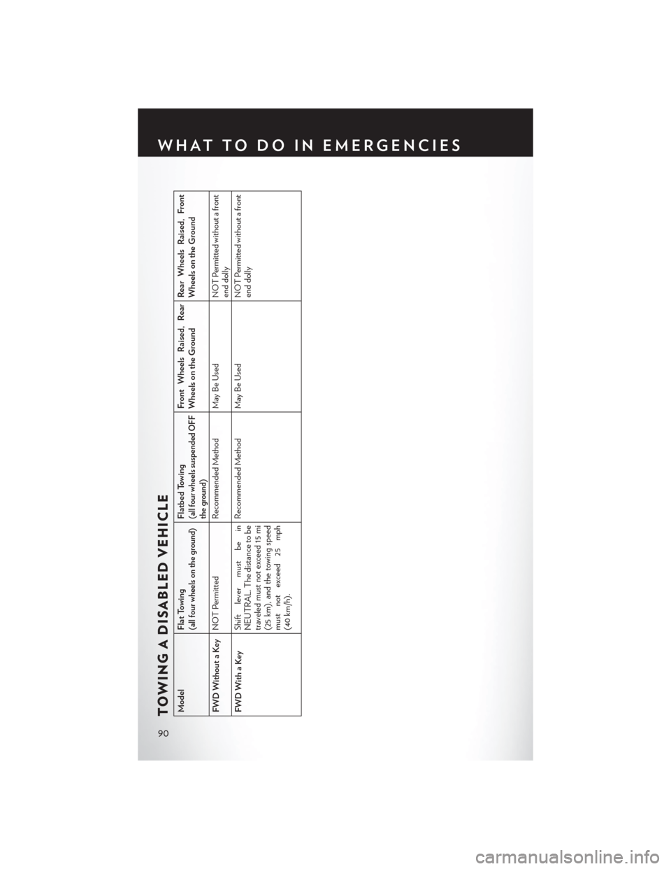
TOWING A DISABLED VEHICLEModelFlat Towing
(all four wheels on the ground)
Flatbed Towing(all four wheels suspended OFF
the ground)
Front Wheels Raised, Rear
Wheels on the Ground Rear Wheels Raised, Front
Wheels on the Ground
FWD Without a Key NOT Permitted Recommended Method May Be Used NOT Permitted without a front
end dolly
FWD With a Key Shift lever must be in
NEUTRAL. The distance to be
traveled must not exceed 15 mi
(25 km), and the towing speed
must not exceed 25 mph
(40 km/h). Recommended Method May Be Used
NOT Permitted without a front
end dolly
WHAT TO DO IN EMERGENCIES
90
Page 93 of 124
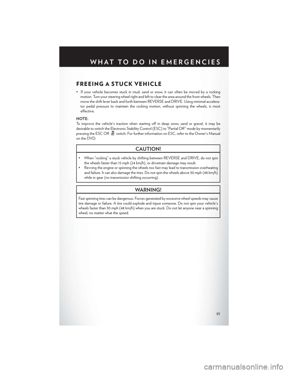
FREEING A STUCK VEHICLE
• If your vehicle becomes stuck in mud, sand or snow, it can often be moved by a rockingmotion. Turn your steering wheel right and left to clear the area around the front wheels. Then
move the shift lever back and forth between REVERSE and DRIVE. Using minimal accelera-
tor pedal pressure to maintain the rocking motion, without spinning the wheels, is most
effective.
NOTE:
To improve the vehicle's traction when starting off in deep snow, sand or gravel, it may be
desirable to switch the Electronic Stability Control (ESC) to “Partial Off ” mode by momentarily
pressing the ESC Off
switch. For further information on ESC, refer to the Owner's Manual
on the DVD.
CAUTION!
• When “rocking” a stuck vehicle by shifting between REVERSE and DRIVE, do not spin the wheels faster than 15 mph (24 km/h), or drivetrain damage may result.
• Revving the engine or spinning the wheels too fast may lead to transmission overheating
and failure. It can also damage the tires. Do not spin the wheels above 30 mph (48 km/h)
while in gear (no transmission shifting occurring).
WARNING!
Fast spinning tires can be dangerous. Forces generated by excessive wheel speeds may cause
tire damage or failure. A tire could explode and injure someone. Do not spin your vehicle's
wheels faster than 30 mph (48 km/h) when you are stuck. Do not let anyone near a spinning
wheel, no matter what the speed.
WHAT TO DO IN EMERGENCIES
91
Page 108 of 124
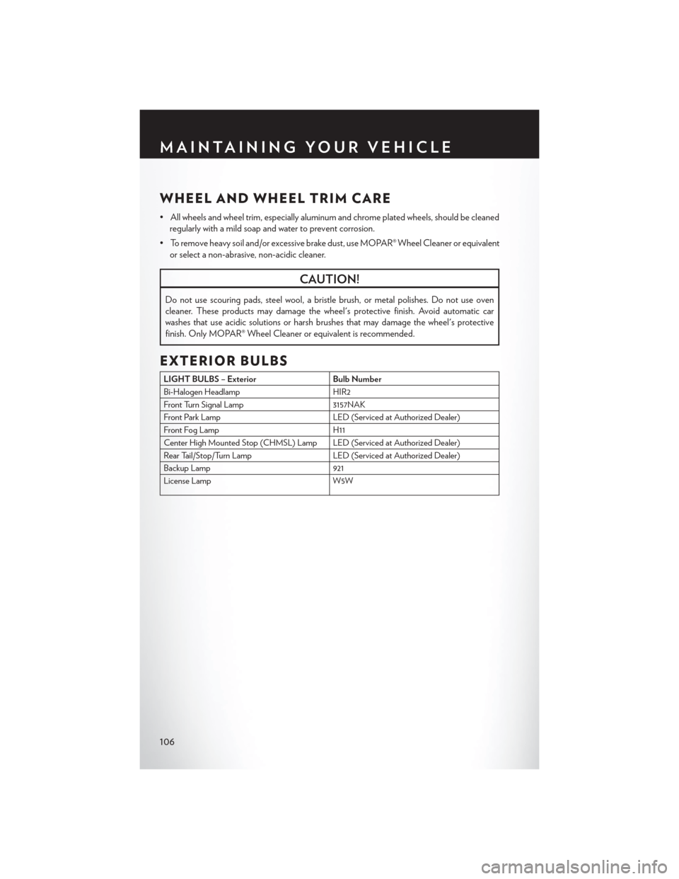
WHEEL AND WHEEL TRIM CARE
• All wheels and wheel trim, especially aluminum and chrome plated wheels, should be cleanedregularly with a mild soap and water to prevent corrosion.
• To remove heavy soil and/or excessive brake dust, use MOPAR® Wheel Cleaner or equivalent or select a non-abrasive, non-acidic cleaner.
CAUTION!
Do not use scouring pads, steel wool, a bristle brush, or metal polishes. Do not use oven
cleaner. These products may damage the wheel's protective finish. Avoid automatic car
washes that use acidic solutions or harsh brushes that may damage the wheel's protective
finish. Only MOPAR® Wheel Cleaner or equivalent is recommended.
EXTERIOR BULBS
LIGHT BULBS – Exterior Bulb Number
Bi-Halogen Headlamp HIR2
Front Turn Signal Lamp 3157NAK
Front Park Lamp LED (Serviced at Authorized Dealer)
Front Fog Lamp H11
Center High Mounted Stop (CHMSL) Lamp LED (Serviced at Authorized Dealer)
Rear Tail/Stop/Turn Lamp LED (Serviced at Authorized Dealer)
Backup Lamp 921
License Lamp W5W
MAINTAINING YOUR VEHICLE
106
Page 111 of 124

AUTHENTIC ACCESSORIES BY MOPAR®
• The following highlights just some of the many Authentic Chrysler Accessories by Mopar®featuring a fit, finish, and functionality specifically for your Chrysler 200 Convertible.
• In choosing Authentic Accessories you gain far more than expressive style, premium protec- tion, or extreme entertainment, you also benefit from enhancing your vehicle with accessories
that have been thoroughly tested and factory-approved.
• For the full line of Authentic Chrysler Accessories by Mopar®, visit your local Chrysler
dealership or online at mopar.com for U.S. residents or mopar.ca for Canadian residents.
EXTERIOR:
• Chrome Exhaust Tip • Grilles • Molded Splash Guards
• Hitch Receiver • Front End Cover • Wheel Locks
• Front Air Deflector • Locking Fuel Cap • Side Sills
• Rear Spoiler
INTERIOR:
• Premium Carpet Floor Mats • Door Sill Guards • Molded Cargo Tray
• Slush Mats • Ambient Light Kit • Roadside Safety Kit
• Katzkin Leather Interiors
ELECTRONICS:
• Front Accent Lighting • Mopar® Web (WiFi) •
Electronic Vehicle Tracking System
• Remote Start
CARRIERS:
• Hitch-mount Bike Carrier
MOPAR ACCESSORIES
109