radio CHRYSLER 300 2012 2.G Owner's Manual
[x] Cancel search | Manufacturer: CHRYSLER, Model Year: 2012, Model line: 300, Model: CHRYSLER 300 2012 2.GPages: 124, PDF Size: 3.67 MB
Page 51 of 124
• The iPod® battery charges when plugged into the USB port (if supported by the specificdevice).
• To route the USB/iPod® cable out of the center console, use the access cut out in the front of the console.
NOTE:
• When connecting your iPod® device for the first time, the system may take several minutesto read your music, depending on the number of files. For example, the system will take
approximately 5 minutes for every 1000 songs loaded on the device. Also during the
reading process, the Shuffle and Browse functions will be disabled. This process is needed to
ensure the full use of your iPod® features and only happens the first time it is connected.
After the first time, the reading process of your iPod® will take considerably less time unless
changes are made or new songs are added to the playlist.
• The USB port supports certain Mini, Classic, Nano, Touch, and iPhone® devices. The USB port also supports playing music from compatible external USB Mass Storage Class
memory devices. Some iPod® software versions may not fully support the USB port features.
Please visit Apple’s website for iPod® software updates.
3. SD Card
• Play songs stored on an SD card inserted into the SD card slot.
• Song playback can be controlled using the radio or Steering Wheel Audio Controls toplay, skip to the next or previous track, browse, and list the contents.
4. Bluetooth® Streaming Audio
• If equipped with Uconnect™ Voice Command, your Bluetooth-equipped iPod® devices,cell phones or other media players, may also be able to stream music to your vehicle's
sound system. Your connected device must be Bluetooth-compatible, and paired with
your Uconnect Touch® system (see Uconnect™ Phone for pairing instructions). You can
access the music from your connected Bluetooth® device by touching the Source soft-key
while in Player mode.
Uconnect™ Phone (Bluetooth® HANDS FREE CALLING)
• If the Uconnect™ PhoneButton exists on your steering wheel, then you have the
Uconnect™ Phone features.
• The Uconnect™ Phone is a voice-activated, hands-free, in-vehicle communications system with Voice Command Capability (see Voice Command section).
• The Uconnect™ Phone allows you to dial a phone number with your mobile phone using simple voice commands or using screen soft-keys.
• Refer to the Understand The Features Of Your Vehicle section of your vehicle's Owner's Manual on the DVD for further details.
NOTE:The Uconnect™ Phone requires a mobile phone equipped with the Bluetooth®
Hands-Free Profile, Version 1.0 or higher. For Uconnect™ customer support, call
1–877–855–8400 or visit www.UconnectPhone.com.
ELECTRONICS
49
Page 52 of 124
Pairing a Phone
• To use the Uconnect™ Phone feature, you must first pair your bluetooth phone with theUconnect™ system.
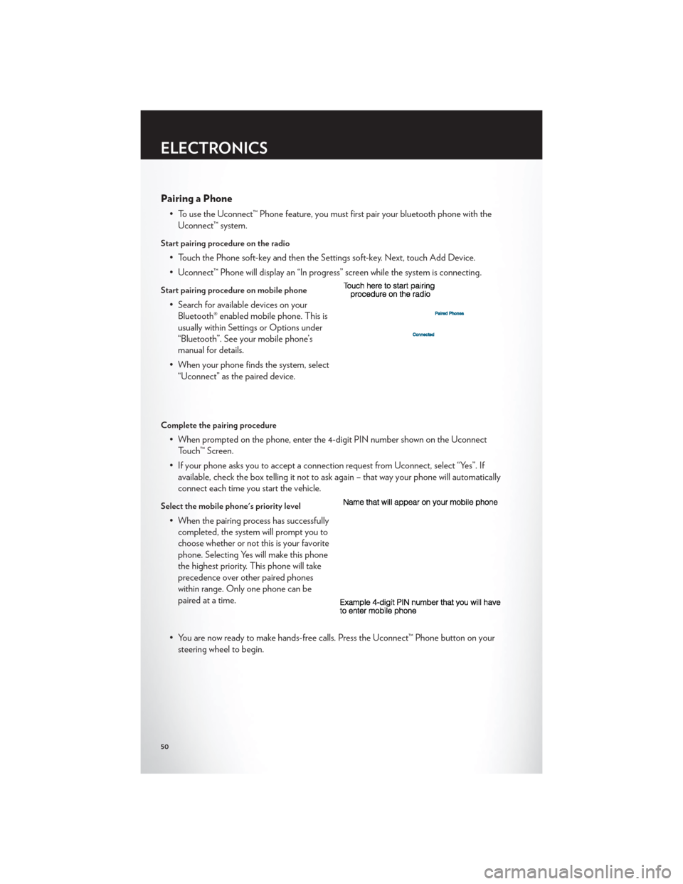
Start pairing procedure on the radio
• Touch the Phone soft-key and then the Settings soft-key. Next, touch Add Device.
• Uconnect™ Phone will display an “In progress” screen while the system is connecting.
Start pairing procedure on mobile phone
• Search for available devices on yourBluetooth® enabled mobile phone. This is
usually within Settings or Options under
“Bluetooth”. See your mobile phone’s
manual for details.
• When your phone finds the system, select “Uconnect” as the paired device.
Complete the pairing procedure
• When prompted on the phone, enter the 4-digit PIN number shown on the UconnectTouch™ Screen.
• If your phone asks you to accept a connection request from Uconnect, select “Yes”. If available, check the box telling it not to ask again – that way your phone will automatically
connect each time you start the vehicle.
Select the mobile phone's priority level
• When the pairing process has successfullycompleted, the system will prompt you to
choose whether or not this is your favorite
phone. Selecting Yes will make this phone
the highest priority. This phone will take
precedence over other paired phones
within range. Only one phone can be
paired at a time.
• You are now ready to make hands-free calls. Press the Uconnect™ Phone button on your steering wheel to begin.
ELECTRONICS
50
Page 54 of 124
Common Phone Commands
Common Phone Commands (Examples)
“Call John Smith”
“Call John Smith mobile”
“Dial 1 248 555 1212”
“Call Emergency”
“Call Towing Assistance”
“Redial”
Phonebook
• Uconnect Touch™ radios will automatically download your phonebook from your pairedphone, if this feature is supported by your phone. Entries are updated each time that the
phone is paired. If your phone book entries do not appear, check the settings on your
phone. Some phones require you to enable this feature manually.
• Your phonebook can be browsed on your radio screen, but editing can only be done on your phone. To browse, touch the Phone soft-key, then the Phonebook soft-key.
• Favorite phonebook entries can be saved as Favorites for quicker access. Favorites are shown at the top of your main phone screen.
Voice Recognition Tips
• Use longer names that are less easily mistaken for others. For examples, say “Call JohnDoe” instead of “Call John”.
• You can “chain” commands together for faster results. Say “Call John Doe, mobile”, for example.
• You can “barge in” while the system is talking to you, enabling you to enter your response without waiting. Just press the Voice Command button on the steering wheel to barge in.
Changing The Volume
• Start a dialogue by pressing the Phone button, then say a command for example -
"Help".
• Use the radio ON/OFF VOLUME rotary knob to adjust the volume to a comfortable level while the Uconnect™ system is speaking. Please note the volume setting for
Uconnect™ is different than the audio system.
NOTE:To access help, press the Uconnect™ Phonebutton on the steering wheel and
say "help." Touch the display or push either
orbutton and say "cancel" to cancel
the help session.
SMS (Text Messaging)
• Uconnect™ Phone can read or send new text messages on your mobile phone.
• Your mobile phone must support SMS over Bluetooth® in order to use this feature. If the Uconnect™ Phone determines your phone is not compatible with SMS messaging over
Bluetooth® the “Messaging” button will be greyed out and the feature will not be available
for use.
ELECTRONICS
52
Page 55 of 124
NOTE:
• For mobile phone compatibility and pairing instructions, please visitwww.UconnectPhone.com
• Uconnect™ Phone SMS is only available when the vehicle is not in moving.
WARNING!
• Any voice commanded system should be used only in safe driving conditions following local laws and phone use. All attention should be kept on the roadway ahead. Failure to
do so may result in a collision causing you and others to be severely injured or killed.
• In an emergency, to use Uconnect™ Phone, your mobile phone must be: • turned on,
• paired to Uconnect™ Phone,
• and have network coverage.
Uconnect™ Voice Command
• If the Uconnect™ Voice Commandbutton exists on your steering wheel, then
you have the Voice Command feature.
• The Voice Command feature lets you keep your hands on the steering wheel, and your eyes on the road.
• When you press the Voice Command button
located on the radio faceplate or
steering wheel, you will hear a beep. The beep is your signal to give a command. If you do
not know what commands to say, you can say "help" and the system will provide options
to you. If you ever wish to interrupt the system while it lists options, press the Voice
Command button
, listen for the BEEP, and say your command.
• You can “chain” commands together for faster results. Say “Call John Doe, mobile”, for example.
Changing The Volume
• Start a dialogue by pressing the Voice Command button, then say a command
(for example, “help”).
• Use the radio ON/OFF VOLUME rotary knob to adjust the volume to a comfortable level while the Voice Command system is speaking. The volume setting for Voice
Command is different than the audio system.
• Refer to the Understand The Features Of Your Vehicle section of your vehicle's Owner's Manual on the DVD for further details.
ELECTRONICS
53
Page 56 of 124
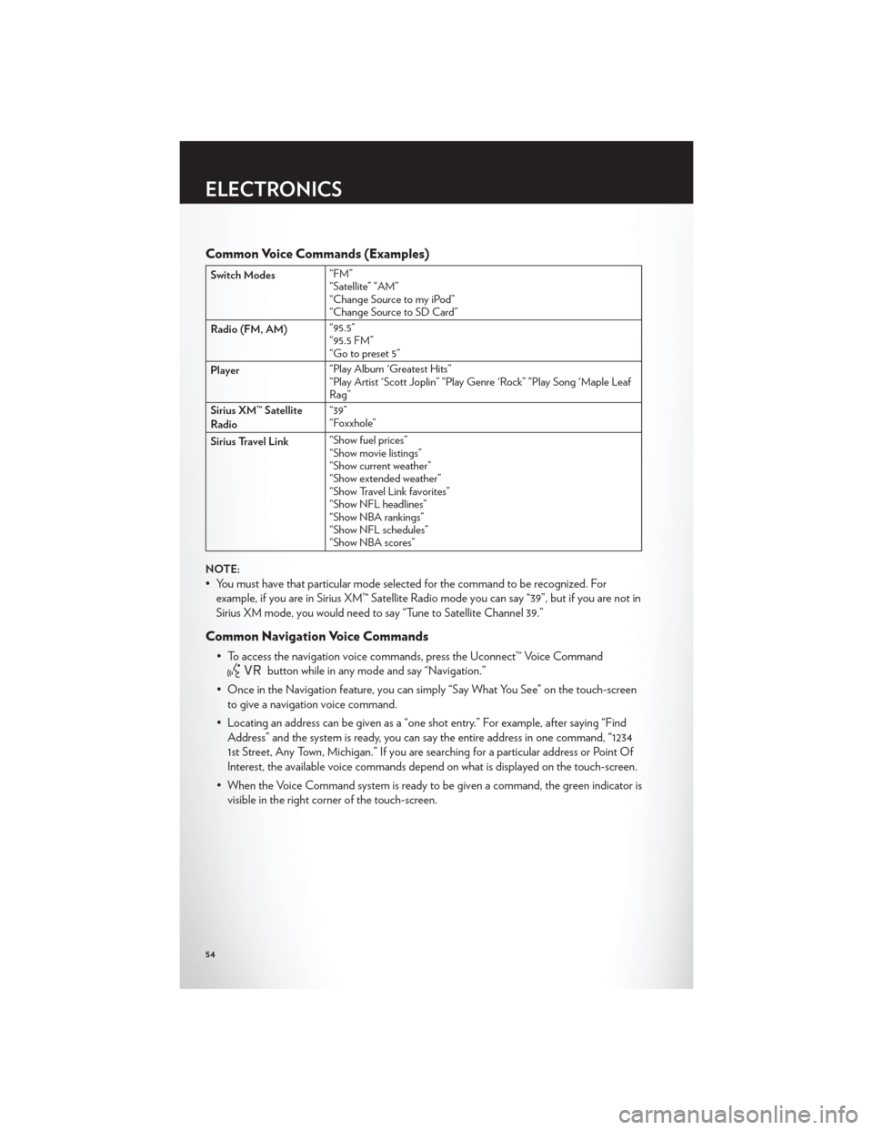
Common Voice Commands (Examples)
Switch Modes“FM”
“Satellite” “AM”
“Change Source to my iPod”
“Change Source to SD Card”
Radio (FM, AM) “95.5”
“95.5 FM”
“Go to preset 5”
Player “Play Album 'Greatest Hits”
“Play Artist 'Scott Joplin” “Play Genre 'Rock” “Play Song 'Maple Leaf
Rag”
Sirius XM™ Satellite
Radio “39”
“Foxxhole”
Sirius Travel Link “Show fuel prices”
“Show movie listings”
“Show current weather”
“Show extended weather”
“Show Travel Link favorites”
“Show NFL headlines”
“Show NBA rankings”
“Show NFL schedules”
“Show NBA scores”
NOTE:
• You must have that particular mode selected for the command to be recognized. For example, if you are in Sirius XM™ Satellite Radio mode you can say “39”, but if you are not in
Sirius XM mode, you would need to say “Tune to Satellite Channel 39.”
Common Navigation Voice Commands
• To access the navigation voice commands, press the Uconnect™ Voice Command
button while in any mode and say “Navigation.”
• Once in the Navigation feature, you can simply “Say What You See” on the touch-screen to give a navigation voice command.
• Locating an address can be given as a “one shot entry.” For example, after saying “Find Address” and the system is ready, you can say the entire address in one command, “1234
1st Street, Any Town, Michigan.” If you are searching for a particular address or Point Of
Interest, the available voice commands depend on what is displayed on the touch-screen.
• When the Voice Command system is ready to be given a command, the green indicator is visible in the right corner of the touch-screen.
ELECTRONICS
54
Page 59 of 124
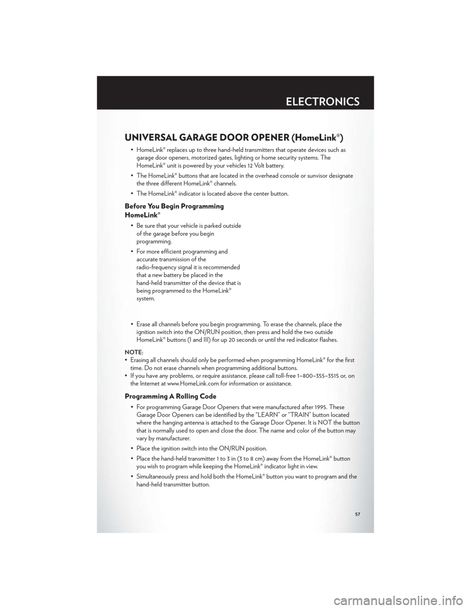
UNIVERSAL GARAGE DOOR OPENER (HomeLink®)
• HomeLink® replaces up to three hand-held transmitters that operate devices such asgarage door openers, motorized gates, lighting or home security systems. The
HomeLink® unit is powered by your vehicles 12 Volt battery.
• The HomeLink® buttons that are located in the overhead console or sunvisor designate the three different HomeLink® channels.
• The HomeLink® indicator is located above the center button.
Before You Begin Programming
HomeLink®
• Be sure that your vehicle is parked outside of the garage before you begin
programming.
• For more efficient programming and accurate transmission of the
radio-frequency signal it is recommended
that a new battery be placed in the
hand-held transmitter of the device that is
being programmed to the HomeLink®
system.
• Erase all channels before you begin programming. To erase the channels, place the ignition switch into the ON/RUN position, then press and hold the two outside
HomeLink® buttons (I and III) for up 20 seconds or until the red indicator flashes.
NOTE:
• Erasing all channels should only be performed when programming HomeLink® for the firsttime. Do not erase channels when programming additional buttons.
• If you have any problems, or require assistance, please call toll-free 1–800–355–3515 or, on the Internet at www.HomeLink.com for information or assistance.
Programming A Rolling Code
• For programming Garage Door Openers that were manufactured after 1995. TheseGarage Door Openers can be identified by the “LEARN” or “TRAIN” button located
where the hanging antenna is attached to the Garage Door Opener. It is NOT the button
that is normally used to open and close the door. The name and color of the button may
vary by manufacturer.
• Place the ignition switch into the ON/RUN position.
• Place the hand-held transmitter 1 to 3 in (3 to 8 cm) away from the HomeLink® button you wish to program while keeping the HomeLink® indicator light in view.
• Simultaneously press and hold both the HomeLink® button you want to program and the hand-held transmitter button.
ELECTRONICS
57
Page 86 of 124

NOTE:The remote battery posts are viewed by standing on the right side of the vehicle
looking over the fender.
• Set the parking brake, shift the automatic transmission into PARK and turn the ignition toOFF.
• Turn off the heater, radio, and all unnecessary electrical accessories.
• If using another vehicle to jump-start the battery, park the vehicle within the jumper cables reach, set the parking brake and make sure the ignition is OFF.
Jump-Starting Procedure
• Connect the positive (+)end of the jumper cable to the remote positive (+)post of the
discharged vehicle.
• Connect the opposite end of the positive (+)jumper cable to the positive(+)post of the
booster battery.
• Connect the negative end (-)of the jumper cable to the negative (-)post of the booster
battery.
• Connect the opposite end of the negative (-)jumper cable to the remote negative(-)post
of the vehicle with the discharged battery.
• Start the engine in the vehicle that has the booster battery, let the engine idle a few minutes, and then start the engine in the vehicle with the discharged battery.
Once the engine is started, remove the jumper cables in the reverse sequence:
• Disconnect the negative (-)
jumper cable from the remote negative (-)post of the vehicle
with the discharged battery.
• Disconnect the negative end (-)of the jumper cable from the negative (-)post of the
booster battery.
• Disconnect the opposite end of the positive (+)jumper cable from the positive(+)post of
the booster battery.
• Disconnect the positive (+)end of the jumper cable from the remote positive (+)post of the
discharged vehicle.
• If frequent jump-starting is required to start your vehicle you should have the battery and charging system inspected at your authorized dealer.
CAUTION!
• Do not use a portable battery booster pack or any other booster source with a systemvoltage greater than 12 Volts or damage to the battery, starter motor, alternator or
electrical system may occur.
• Failure to follow these procedures could result in damage to the charging system of the booster vehicle or the discharged vehicle.
• Accessories that can be plugged into the vehicle power outlets draw power from the vehicle’s battery, even when not in use (i.e., cellular phones, etc.). Eventually, if plugged in
long enough, the vehicle’s battery will discharge sufficiently to degrade battery life
and/or prevent the engine from starting.
WHAT TO DO IN EMERGENCIES
84
Page 109 of 124

Cavity Cartridge Fuse Mini-Fuse Description2 60 Amp Yellow — Front PDC Feed #1
4 60 Amp Yellow — Front PDC Feed #2 5 30 Amp Pink — Sunroof
6 40 Amp Green — Exterior Lighting #1 7 40 Amp Green — Exterior Lighting #2
8 30 Amp Pink — Interior Lighting/Washer Pump 9 30 Amp Pink — Power Locks
10 30 Amp Pink — Driver Door 11 30 Amp Pink — Passenger Door
12 — 20 Amp Yellow Cigar Lighters (Selectable)
15 40 Amp Green — HVAC Blower
23 — 10 Amp Red Fuel Door/Diagnostic Port
24 — 15 Amp Blue Radio Screen 25 — 10 Amp Red Tire Pressure Monitor 27 — 25 Amp Neutral Amplifier 31 — 25 Amp Neutral Power Seats
32 — 15 Amp Blue HVAC Module/Cluster 33 — 15 Amp Blue Ignition Switch/Wireless Module
34 — 10 Amp Red Steering Column Module/Clock 35 — 10 Amp Red Battery Sensor 37 — 15 Amp Blue Radio
38 — 20 Amp Yellow Power Outlet
42 30 Amp Pink — Rear Defrost 43 — 25 Amp Neutral Rear Heated Seats/Steering Wheel
44 — 10 Amp Red Park Assist/Blind Spot/Camera 45 — 15 Amp Blue Cluster/Rearview Mirror/Compass
46 — 10 Amp Red Adaptive Cruise Control 47 — 10 Amp Red Adaptive Front Lighting
48 — 20 Amp Yellow Active Suspension 51 — 20 Amp Yellow Front Heated Seats
52 — 10 Amp Red Heated Cupholders/Rear Heated Seat Switches 53 — 10 Amp Red HVAC Module/In Car Temperature Sensor
58 — 10 Amp Red Airbag Module
64 — 25 Amp Neutral Rear Windows 65 — 10 Amp Red Airbag Module 67 — 15 Amp Blue Run Sense
68 — 15 Amp Blue Power Outlet Illumination/Rear Sunshade
MAINTAINING YOUR VEHICLE
107
Page 112 of 124

CHRYSLER GROUP LLC CUSTOMER CENTER
P.O. Box 21–8004
Auburn Hills, MI 48321–8004
Phone: 1–800–247–9753
CHRYSLER CANADA INC. CUSTOMER CENTER
P.O. Box 1621
Windsor, Ontario N9A 4H6
Phone: 1–800–465–2001 (English)
Phone: 1–800–387–9983 (French)
ASSISTANCE FOR THE HEARING IMPAIRED
• To assist customers who have hearing difficulties, the manufacturer has installed specialTDD (Telecommunication Devices for the Deaf ) equipment at its customer center. Any
hearing or speech impaired customer, who has access to a TDD or a conventional
teletypewriter (TTY) in the United States, can communicate with the manufacturer by
dialing 1–800–380–CHRY. Canadian residents with hearing difficulties that require
assistance can use the special needs relay service offered by Bell Canada. For TTY
teletypewriter users, dial 711 and for Voice callers, dial 1–800–855–0511 to connect with a
Bell Relay Service operator.
WARNING!
Engine exhaust, some of its constituents, and certain vehicle components contain, or emit,
chemicals known to the State of California to cause cancer and birth defects, or other
reproductive harm. In addition, certain fluids contained in vehicles and certain products of
component wear contain, or emit, chemicals known to the State of California to cause
cancer and birth defects, or other reproductive harm.
PUBLICATIONS ORDERING
•If you are the first registered retail owner of your vehicle,you may obtain one free
printed copy of the Owner's Manual, Warranty Booklet or Radio Manuals on your DVD by
calling 1–800–247–9753 (U.S.) or 1–800–387–1143 (Canada) or by contacting your dealer.
• Replacement User Guide kits or DVDs or, if you prefer, additional printed copies of the Owner's Manual, Warranty Booklet or Radio Manuals may be purchased by visiting
www.techauthority.com or by calling 1–800–890–4038 (U.S.) or 1–800–387–1143
(Canada). Visa, Master Card, American Express and Discover orders are accepted. If you
prefer mailing your order, please call the above numbers for an order form.
NOTE:A street address is required when ordering manuals (no P.O. Boxes).
CONSUMER ASSISTANCE
110
Page 116 of 124
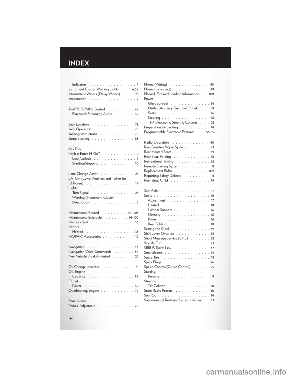
Indicators.................7
Instrument Cluster Warning Lights ....6,68
Intermittent Wipers (Delay Wipers) ....23
Introduction .................2
iPod®/USB/MP3 Control .........48
Bluetooth Streaming Audio .......49
Jack Location ...............73
Jack Operation ..............75
Jacking Instructions ............75
Jump Starting ...............83
KeyFob...................8
Keyless Enter-N-Go™ ............9
Lock/Unlock ...............9
Starting/Stopping ............10
Lane Change Assist ............23
LATCH (Lower Anchors and Tether for
CHildren) .................14
Lights Turn Signal ...............23
Warning (Instrument Cluster
Description) ...............6
Maintenance Record .........101,103
Maintenance Schedule ........99,102
MemorySeat ...............16
Mirrors Heated .................33
MOPAR® Accessories ...........112
Navigation .................44
Navigation Voice Commands .......54
New Vehicle Break-In Period ........22
Oil Change Indicator ............71
Oil, Engine Capacity ................96
Outlet Power ..................59
Overheating, Engine ............72
Panic Alarm .................8
Pedals, Adjustable .............20 Phone (Pairing)
..............50
Phone (Uconnect) .............49
Placard, Tire and Loading Information . . 108
Power Glass Sunroof ..............34
Outlet (Auxiliary Electrical Outlet) . . . 59
Seats ..................16
Steering .................96
Tilt/Telescoping Steering Column ....21
Preparation for Jacking ..........74
Programmable Electronic Features . . . 56,65
Radio Operation .............40
Rain Sensitive Wiper System ........23
Rear Heated Seats .............19
Rear Seat, Folding .............18
Recreational Towing ............62
Remote Starting System ..........8
Replacement Bulbs ............109
Reporting Safety Defects .........111
Restraints, Child ..............14
Seat Belts .................
12
Seats ....................16
Adjustment ...............17
Heated .................18
Lumbar Support .............16
Memory.................16
Power ..................16
Rear Folding ..............18
Setting the Clock .............39
Shift Lever Override ............85
Short Message Service (SMS) .......52
Signals, Turn ................23
SIRIUS Travel Link .............47
SmartBeams ................24
SpareTire .................73
Spark Plugs ................96
Speed Control (Cruise Control) ......25
Starting Remote .................8
Steering TiltColumn ...............20
Store Radio Presets ............40
SunRoof .................34
Supplemental Restraint System - Airbag . . 13
INDEX
114